When parts stack together in a mechanical assembly, their individual dimensional variations add up — and if you haven't accounted for that accumulation, you'll end up with assemblies that don't fit, bind, or fail to meet spec. Use this Tolerance Stack-Up Calculator to calculate worst-case and RSS gap variations using each part's nominal dimension and bilateral tolerance. It matters in precision manufacturing, linear actuator mounting systems, aerospace assemblies, and anywhere tight clearances are non-negotiable. This page includes the full formula, a worked example, engineering theory, and an FAQ.
What is tolerance stack-up?
Tolerance stack-up is the cumulative effect of individual part dimensional variations on the overall size of an assembled product. When parts are joined together, each part's tolerance adds to the next — the total variation at the assembly level can be much larger than any single part tolerance alone.
Simple Explanation
Think of stacking several wooden blocks end-to-end — each block might be slightly longer or shorter than its target size. By the time you stack 5 of them, those small errors can add up to a noticeable gap or interference at the end. Tolerance stack-up analysis tells you exactly how bad that combined error could get, so you can design your assembly to handle it.
📐 Browse all 1000+ Interactive Calculators

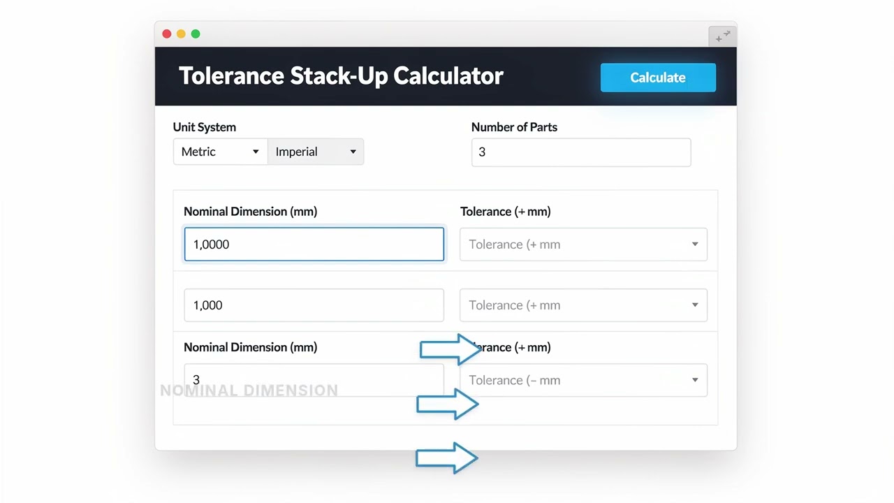
How to Use This Calculator
- Select your unit system — metric (mm) or imperial (inches).
- Enter the number of parts in your assembly (2–10).
- For each part, enter the nominal dimension and its bilateral tolerance (±).
- Click Calculate to see your result.
Tolerance Stack-Up Calculator
📹 Video Walkthrough — How to Use This Calculator
Tolerance Stack-Up interactive visualizer
Watch how individual part tolerances accumulate in assemblies using worst-case and RSS methods. Adjust part dimensions and tolerances to see real-time stack-up calculations for precision manufacturing applications.
WORST CASE
±0.60 mm
RSS METHOD
±0.30 mm
NOMINAL TOTAL
120.0 mm
FIRGELLI Automations — Interactive Engineering Calculators
Mathematical Equations
Worst Case Method
Use the formula below to calculate worst-case tolerance accumulation.
WC = Σ|toli|
Where WC is the worst-case tolerance accumulation and toli is the tolerance of the i-th component.
Root Sum Square (RSS) Method
Use the formula below to calculate RSS tolerance accumulation.
RSS = √(Σtoli²)
Where RSS is the root sum square tolerance accumulation and toli is the tolerance of the i-th component.
Simple Example
3 parts in a linear assembly, each with a 0.05 mm tolerance:
- Nominal dimensions: 50.00 mm, 30.00 mm, 20.00 mm → Total nominal = 100.00 mm
- Worst case: 0.05 + 0.05 + 0.05 = ±0.15 mm → Assembly range: 99.85–100.15 mm
- RSS: √(0.05² + 0.05² + 0.05²) = √0.0075 = ±0.087 mm → Assembly range: 99.913–100.087 mm
Complete Technical Guide to Tolerance Stack-Up Analysis
Tolerance stack-up analysis is a fundamental engineering practice that determines how individual part tolerances combine to affect the overall assembly dimensions and functionality. This tolerance stack up calculator provides both worst-case and RSS analysis methods, each serving different purposes in engineering design and manufacturing quality control.
Understanding Tolerance Stack-Up Fundamentals
When multiple parts are assembled together, their individual dimensional variations combine to create an overall assembly variation. Consider a simple linear assembly where five parts are placed end-to-end. Each part has a nominal dimension with an associated tolerance. The question becomes: what is the total possible variation in the overall assembly length?
There are two primary methods for calculating tolerance stack-up: the worst-case method and the root sum square (RSS) method. The choice between these methods depends on the criticality of the application, manufacturing processes, and risk tolerance.
Worst-Case Analysis
The worst-case method assumes that all tolerances stack up in the most unfavorable direction simultaneously. This approach provides the absolute maximum and minimum possible dimensions of the assembly. While this method is conservative, it ensures that 100% of parts will meet the specified requirements if manufactured within tolerance.
The worst-case calculation simply adds all individual tolerances: WC = Σ|toli|. This method is particularly appropriate for:
- Critical safety applications
- Small quantity production runs
- Assemblies where part interchangeability is crucial
- Applications where failure costs are extremely high
Root Sum Square (RSS) Analysis
The RSS method is based on statistical principles and assumes that individual part dimensions follow a normal distribution. This approach recognizes that the probability of all parts being at their extreme tolerances simultaneously is extremely low. The RSS calculation is: RSS = √(Σtoli²).
RSS analysis typically results in tighter tolerance requirements compared to worst-case analysis, making it suitable for:
- High-volume production
- Cost-sensitive applications
- Assemblies with many components
- Applications where statistical quality control is employed
Practical Example: Linear Actuator Assembly
Consider designing a mounting bracket for FIRGELLI linear actuators. The assembly consists of five components with the following specifications:
- Base plate: 100.00 ± 0.10 mm
- Spacer 1: 25.00 ± 0.05 mm
- Bracket body: 150.00 ± 0.15 mm
- Spacer 2: 30.00 ± 0.08 mm
- End cap: 45.00 ± 0.06 mm
Using the worst-case method:
Total nominal dimension = 100.00 + 25.00 + 150.00 + 30.00 + 45.00 = 350.00 mm
Worst-case tolerance = 0.10 + 0.05 + 0.15 + 0.08 + 0.06 = 0.44 mm
Assembly dimension range = 350.00 ± 0.44 mm (349.56 to 350.44 mm)
Using the RSS method:
RSS tolerance = √(0.10² + 0.05² + 0.15² + 0.08² + 0.06²) = √(0.0374) = 0.193 mm
Assembly dimension range = 350.00 ± 0.193 mm (349.807 to 350.193 mm)
The RSS method provides a significantly tighter tolerance band, which can lead to cost savings in manufacturing while maintaining acceptable quality levels for most applications.
Design Considerations and Best Practices
When performing tolerance stack-up analysis, several factors must be considered to ensure accurate results and optimal design decisions:
Manufacturing Process Selection
Different manufacturing processes have inherent capabilities and limitations. Machined components typically have tighter tolerances than cast or molded parts. When designing assemblies involving linear actuators and precision mechanisms, consider the manufacturing process for each component and specify tolerances accordingly.
Tolerance Allocation Strategy
Not all components in an assembly need the same tolerance. Strategic tolerance allocation can optimize manufacturing costs while meeting assembly requirements. Typically, smaller or less critical components can have looser tolerances, while key functional surfaces require tighter control.
Assembly Method Impact
The method of assembly can significantly affect tolerance stack-up. Fixed assemblies (permanently joined) behave differently from adjustable assemblies. For applications involving linear actuators, consider whether adjustment mechanisms can compensate for tolerance variations.
Environmental Factors
Temperature variations, material properties, and environmental conditions can affect dimensional stability. In precision applications, thermal expansion coefficients and long-term dimensional stability must be factored into the tolerance analysis.
Advanced Tolerance Analysis Techniques
Monte Carlo Simulation
For complex assemblies with many components, Monte Carlo simulation provides a more sophisticated approach to tolerance analysis. This method randomly samples from the tolerance distributions of individual components to predict the assembly variation distribution.
Six Sigma Methodology
Six Sigma approaches to tolerance stack-up focus on process capability and defect prevention. This methodology considers both the tolerance requirements and the manufacturing process capability to optimize quality and cost.
Applications in Linear Actuator Systems
Tolerance stack-up analysis is particularly critical in linear actuator applications where precise positioning is required. When designing mounting systems for linear actuators, consider:
- Alignment tolerances between mounting brackets
- Clearance requirements for actuator stroke
- Bearing surface tolerances for smooth operation
- Connection interface tolerances
For systems requiring high precision, RSS analysis may be appropriate for cost optimization, while safety-critical applications may require worst-case analysis to ensure reliable operation under all conditions.
Quality Control and Verification
After completing tolerance stack-up calculations, verification through measurement and testing is essential. Statistical process control (SPC) methods can monitor actual assembly dimensions against predicted values, validating the tolerance analysis assumptions and identifying opportunities for improvement.
Regular review of tolerance stack-up calculations ensures that design changes, process improvements, and supplier variations are properly accounted for in the overall assembly tolerances.
Frequently Asked Questions
📐 Browse all 1000+ Interactive Calculators →
About the Author
Robbie Dickson
Chief Engineer & Founder, FIRGELLI Automations
Robbie Dickson brings over two decades of engineering expertise to FIRGELLI Automations. With a distinguished career at Rolls-Royce, BMW, and Ford, he has deep expertise in mechanical systems, actuator technology, and precision engineering.
🔗 Related Engineering Calculators
More related engineering calculators:
- Thread Pitch Calculator Metric and Imperial
- Press Fit Calculator Interference and Force
- Runout Calculator Circular and Total Runout
- Floating Fastener Calculator GD T Position
- Fixed Fastener Calculator GD T Position
- True Position Calculator From X Y Data
- Shaft Hole Fit Calculator ISO 286
- Flat Plate Stress and Deflection Calculator
- Torsional Stress Calculator Solid and Hollow Shafts
- Strain Calculator Engineering and True
Browse all engineering calculators →
Need to implement these calculations?
Explore the precision-engineered motion control solutions used by top engineers.


