Precise motion control falls apart fast if you don't know your stepper motor's actual angular resolution — especially when microstepping drivers and lead screws are in the mix. Use this Stepper Motor Step Angle & Resolution Calculator to calculate step angle, total steps per revolution, and linear positioning resolution using full steps per revolution, microstep division, and lead screw pitch. It matters most in CNC machining, 3D printing, and laboratory automation, where positioning errors compound over distance. This page includes the governing formulas, a worked example, full technical theory, and an FAQ.
What is stepper motor step angle and resolution?
Step angle is the number of degrees a stepper motor rotates per electrical pulse. Resolution is the smallest position increment your system can command — made finer by microstepping and by the pitch of any lead screw attached to the motor shaft.
Simple Explanation
Think of a stepper motor like a clock hand that moves in fixed clicks instead of sweeping smoothly. Each click is one step. Microstepping breaks each click into smaller sub-clicks, so the motor can land on more precise positions. If that motor drives a threaded rod, each sub-click moves the rod a tiny, predictable distance — that distance is your linear resolution.
📐 Browse all 384 free engineering calculators

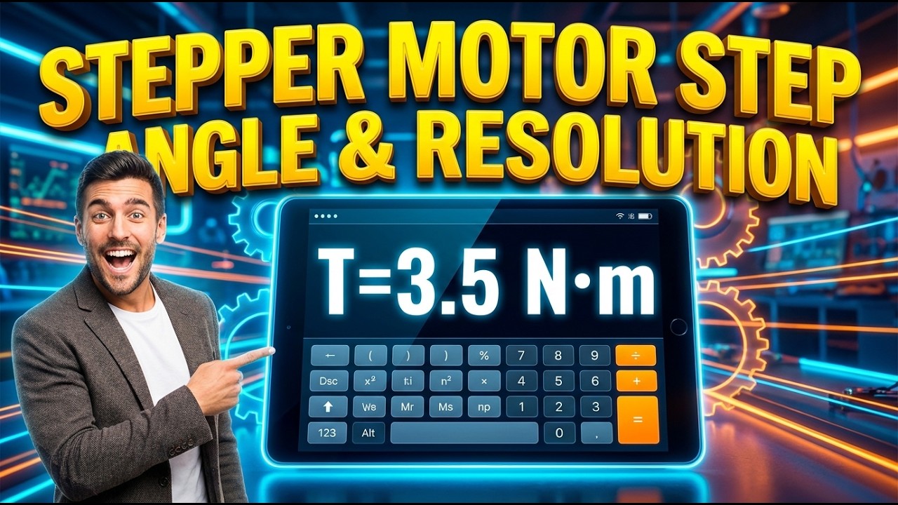
Stepper Motor Step Angle & Resolution Interactive Visualizer
Watch how microstepping divides each motor step into precise increments, and see how lead screw pitch converts angular motion into linear positioning resolution. Adjust motor specs and microstepping to instantly calculate your system's true positioning capabilities.
STEP ANGLE
1.8°
TOTAL STEPS
3,200
MICROSTEP ANGLE
0.1125°
LINEAR RES
0.625 μm
FIRGELLI Automations — Interactive Engineering Calculators
How to Use This Calculator
- Enter the full steps per revolution for your stepper motor — 200 is standard for a 1.8° motor, 400 for a 0.9° motor.
- Select your microstep division from the dropdown — this is set by your motor driver (e.g., 16 for 16× microstepping).
- Optionally, enter your lead screw pitch and select the unit (mm, inches, or threads per inch) to get linear resolution per step.
- Click Calculate to see your result.
Stepper Motor Step Angle Calculator
📹 Video Walkthrough — How to Use This Calculator
Mathematical Equations
Step Angle Calculation:
Use the formula below to calculate step angle.
θ = 360° ÷ (Sfull × Mdiv)
Total Steps per Revolution:
Use the formula below to calculate total steps per revolution.
Stotal = Sfull × Mdiv
Linear Resolution (with lead screw):
Use the formula below to calculate linear resolution per step.
Rlinear = P ÷ Stotal
Where:
- θ = Step angle (degrees)
- Sfull = Full steps per revolution
- Mdiv = Microstep division factor
- Stotal = Total microsteps per revolution
- P = Lead screw pitch (distance per revolution)
- Rlinear = Linear resolution per step
Simple Example
Motor: 200 full steps per revolution. Driver: 16× microstepping. Lead screw: 2 mm pitch.
- Total steps per revolution = 200 × 16 = 3,200
- Step angle = 360° ÷ 3,200 = 0.1125°
- Linear resolution = 2 mm ÷ 3,200 = 0.000625 mm = 0.625 μm
Understanding Stepper Motor Step Angles and Resolution
Fundamentals of Stepper Motor Operation
Stepper motors are precision positioning devices that rotate in discrete angular increments called steps. Unlike continuous rotation motors, stepper motors move in precise, repeatable angular positions, making them ideal for applications requiring accurate positioning without feedback sensors.
The step angle is the fundamental characteristic that defines a stepper motor's resolution. It represents the angular displacement of the rotor for each input pulse to the motor driver. Common stepper motors have step angles of 1.8° (200 steps per revolution) or 0.9° (400 steps per revolution).
Microstepping Technology
Microstepping is a driver technique that subdivides each full step into smaller increments by varying the current in the motor windings. Instead of switching current on and off abruptly, microstepping drivers use sinusoidal current control to position the rotor at intermediate positions between full steps.
Common microstepping divisions include 2, 4, 8, 16, 32, 64, 128, and 256 microsteps per full step. For example, a 200-step motor with 16× microstepping provides 3,200 steps per revolution, resulting in a step angle of 0.1125°.
Benefits and Limitations of Microstepping
Benefits:
- Increased resolution and smoother motion
- Reduced vibration and noise
- Better low-speed performance
- Improved positional accuracy for small moves
Limitations:
- Reduced torque at microstep positions
- Non-linear step accuracy between detent positions
- Potential resonance issues at certain speeds
- Increased driver complexity and cost
Linear Motion Applications
When stepper motors drive lead screws or ball screws, rotational motion converts to linear motion. The linear resolution depends on both the motor's angular resolution and the screw's pitch (distance traveled per revolution).
For precision linear actuator applications, FIRGELLI linear actuators often employ stepper motors with fine-pitch lead screws to achieve high positioning accuracy. The relationship between rotational and linear resolution is critical for determining system performance.
Worked Example: High-Precision Positioning System
Consider a precision positioning system with the following specifications:
- Stepper motor: 200 full steps per revolution (1.8° step angle)
- Driver: 32× microstepping
- Lead screw: 2mm pitch
Calculations:
Total steps per revolution = 200 × 32 = 6,400 steps
Microstep angle = 360° ÷ 6,400 = 0.05625°
Linear resolution = 2mm ÷ 6,400 = 0.0003125mm = 0.3125 μm
This system provides sub-micron theoretical resolution, suitable for precision manufacturing, laboratory automation, or optical positioning applications.
Design Considerations
Motor Selection: Choose motors with appropriate step angles for your resolution requirements. Higher step count motors (400 steps/rev) provide better base resolution but may have different torque characteristics.
Microstepping Level: Higher microstep divisions increase resolution but reduce holding torque between full steps. Consider the load requirements and positioning accuracy needs when selecting microstep levels.
Lead Screw Selection: Fine-pitch screws provide better linear resolution but may increase system backlash and reduce speed. Ball screws offer better efficiency and reduced backlash compared to lead screws.
Driver Quality: High-quality microstepping drivers with accurate current control provide better step uniformity and reduced positioning errors.
Accuracy vs. Resolution
It's important to distinguish between resolution and accuracy. Resolution is the smallest increment the system can command, while accuracy is how close the actual position matches the commanded position.
Factors affecting accuracy include:
- Motor step angle tolerance (typically ±3-5%)
- Microstepping non-linearity
- Mechanical backlash in the drive system
- Load-induced deflection
- Temperature effects on components
Practical Applications
3D Printing: Stepper motors with microstepping provide smooth layer positioning and precise filament extrusion control.
CNC Machining: High-resolution stepper systems enable precise tool positioning for detailed machining operations.
Laboratory Automation: Microscope stages, sample positioning, and pipetting systems rely on stepper motor precision.
Optical Systems: Mirror positioning, lens focusing, and beam steering applications benefit from smooth, precise stepper motor control.
Integration with Control Systems
Modern stepper motor controllers often include advanced features like:
- Closed-loop feedback for improved accuracy
- Anti-resonance algorithms
- Automatic current reduction for energy efficiency
- Communication interfaces (USB, Ethernet, RS-485)
When designing systems with stepper motors, consider using our engineering calculators for related calculations such as torque requirements, speed profiles, and power consumption.
Future Trends
Stepper motor technology continues advancing with improvements in driver electronics, motor design, and control algorithms. Integrated stepper motors with built-in drives and communication capabilities are becoming more common, simplifying system integration while maintaining precision performance.
Frequently Asked Questions
📐 Explore our full library of 384 free engineering calculators →
About the Author
Robbie Dickson
Chief Engineer & Founder, FIRGELLI Automations
Robbie Dickson brings over two decades of engineering expertise to FIRGELLI Automations. With a distinguished career at Rolls-Royce, BMW, and Ford, he has deep expertise in mechanical systems, actuator technology, and precision engineering.
🔗 Explore More Free Engineering Calculators
Need to implement these calculations?
Explore the precision-engineered motion control solutions used by top engineers.


