To put a robot arm’s end-effector exactly where you want it, you work backwards from the target, not forwards from the start. This is inverse kinematics. The calculator below figures out the joint angles needed to hit any target XY position, as long as you feed in your link lengths and, for 3-link arms, your desired end-effector orientation. It supports both 2-link and 3-link planar arms. You’ll find the necessary equations, a worked example, and basic checks for what’s actually reachable.
What is inverse kinematics?
Inverse kinematics (IK) is just finding out which joint angles will put the robot’s end-effector at a specific point. Start with a target location, and IK tells you how to move each joint to hit that point.
Simple Explanation
Think about reaching for something with your own arm. Your brain sets your hand on the target by automatically figuring out how much to bend your shoulder and elbow—you don’t run any equations in your head. IK applies that kind of calculation, but mathematically, so a robot can do the same. Longer links let you reach farther, but how much each joint needs to rotate depends on exactly where your endpoint is.
📐 Browse all 1000+ Interactive Calculators
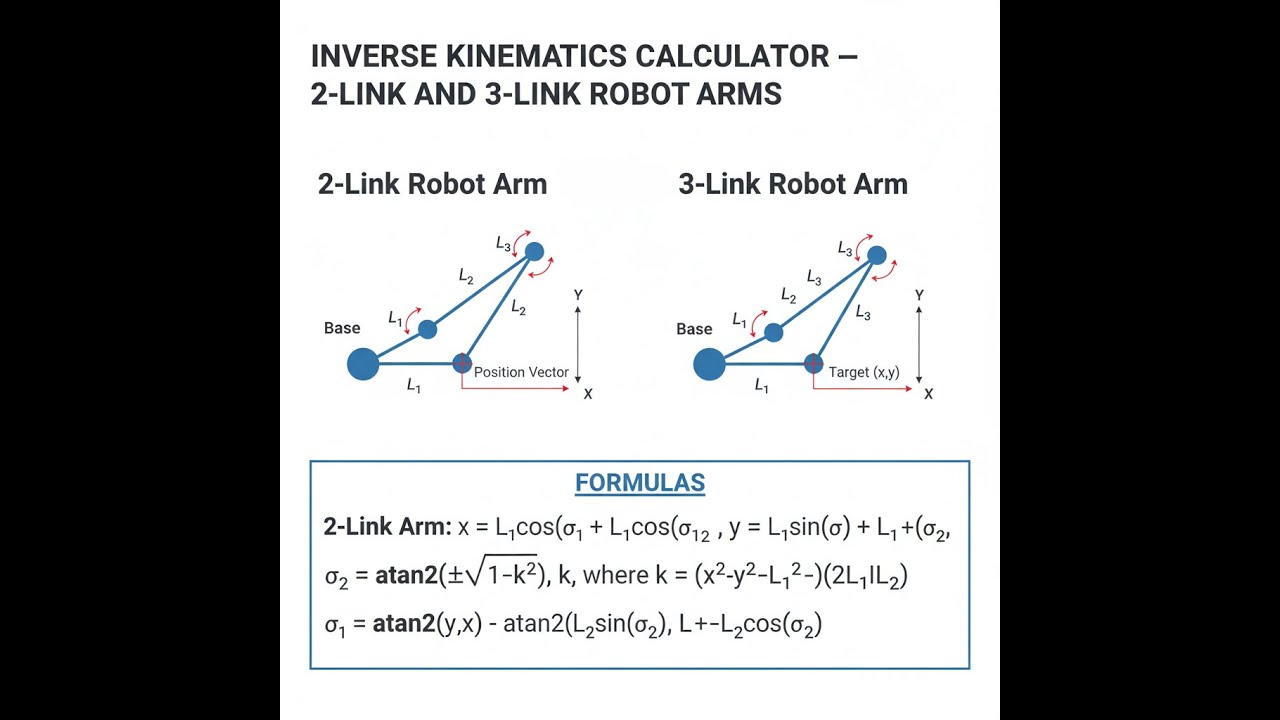
Robot Arm Kinematics Diagram

inverse kinematics interactive visualizer
Move the target crosshair and you'll see the robot arm instantly update its calculated joint angles. Switch between 2-link and 3-link to see how adding another joint changes what you can reach and control.
ANGLE θ₁
--°
ANGLE θ₂
--°
REACHABLE
YES
FIRGELLI Automations — Interactive Engineering Calculators
How to Use This Calculator
- Pick 2-link or 3-link from the dropdown.
- Input the length for each link (L₁, L₂, and L₃ if you need it) in your units.
- Add the Target X and Y coordinates. For a 3-link arm, put in the end-effector orientation in degrees too.
- Press Calculate to see your results.
Inverse Kinematics Calculator
This calculator is intended for education, concept evaluation, and preliminary design. Results are based on the equations and assumptions described on this page, but cannot account for every real-world load case, tolerance, material property, environmental condition, installation detail, safety factor, code, or regulatory requirement. Verify all inputs, assumptions, units, and results independently before selecting components or using the result in a real application. Safety-critical, structural, medical, lifting, transportation, or regulated applications must be reviewed by a qualified engineer.
Questions about this calculator or found an error? Message our engineering team.
Mathematical Equations
2-Link Robot Arm Inverse Kinematics
For a 2-link planar robot arm, the inverse kinematics equations are:
Use the formula below to calculate joint angles for a 2-link planar robot arm.
Joint Angle 2:
θ₂ = acos((x² + y² - L₁² - L₂²) / (2L₁L₂))
Joint Angle 1:
θ₁ = atan2(y, x) - atan2(L₂sin(θ₂), L₁ + L₂cos(θ₂))
Reachability Condition:
|L₁ - L₂| ≤ √(x² + y²) ≤ L₁ + L₂
3-Link Robot Arm Inverse Kinematics
For a 3-link planar robot arm with specified end-effector orientation:
Use the formula below to calculate joint angles for a 3-link planar robot arm.
Wrist Position:
wx = x - L₃cos(φ)
wy = y - L₃sin(φ)
First Two Joint Angles (same as 2-link for wrist position):
θ₂ = acos((wx² + wy² - L₁² - L₂²) / (2L₁L₂))
θ₁ = atan2(wy, wx) - atan2(L₂sin(θ₂), L₁ + L₂cos(θ₂))
Third Joint Angle:
θ₃ = φ - θ₁ - θ₂
Simple Example
2-link arm, L₁ = 100mm, L₂ = 80mm, target position (120, 90):
- Distance to target = √(120² + 90²) = 150mm — within reach range of 20mm to 180mm.
- θ₂ = arccos((14400 + 8100 − 10000 − 6400) / 16000) = arccos(0.38125) = 67.59°
- θ₁ = atan2(90, 120) − atan2(73.95, 130.5) = 36.87° − 29.55° = 7.32°
Technical Analysis and Applications
Understanding Inverse Kinematics
Inverse kinematics is about working out what angles your joints need so the tool or gripper goes where you want it. Forward kinematics is the opposite: you give it the joint angles, and it tells you where the end winds up. For simple setups, IK isn’t too bad, but as you add more joints and degrees of freedom, these calculations quickly get more involved.
This IK calculator gets you the joint values you need for automation, prototyping, or troubleshooting in robot design. Adding more degrees of freedom increases calculation complexity fast; having a practical IK calculator saves time and head-scratching in the field when setting up paths or debugging reach problems.
2-Link vs 3-Link Robot Arms
A 2-link setup gets you XY positioning within its workspace, but you can’t control end-effector orientation—not without extra joints. That’s fine for simple pick-and-place jobs where the angle of approach doesn’t matter.
With a 3-link, you get position and you can also choose the angle of the end-effector. That’s often required for assembly, insertion, welding, or jobs where you need the tool aimed a particular way.
Workspace and Reachability
A robot arm’s workspace depends entirely on the link lengths. For 2-link arms, what you can reach forms a ring—the distance from the base can never be less than the difference of the two link lengths, nor more than their sum. If your target is inside that ring, it’s not physically possible. Always check reachability before expecting any solution from IK.
Practical Applications
Some common areas where IK shows up on the shop floor or in labs:
- Manufacturing Automation: Robots and CNCs need these calculations to precisely follow programmed paths.
- Assembly Lines: All pick-and-place systems rely on hitting target positions repeatedly, which comes back to IK.
- Welding and Cutting: Getting the torch or cutter into the right spot and angle depends on these joint calculations.
- Medical Robotics: Surgery and inspection robots use IK for controlled movement inside tight spaces.
- Inspection Systems: Automated sensors or cameras are often positioned by arms driven based on IK routines.
In a lot of these robots, FIRGELLI linear actuators are used to drive the links—making precise motion possible by converting IK outputs into real movement.
Worked Example
Here’s a run through for a typical case: two-link arm, L₁ = 100 mm, L₂ = 80 mm, target at (120 mm, 90 mm):
Step 1: Check Reachability
Distance to target = √(120² + 90²) = √(14400 + 8100) = √22500 = 150 mm
Minimum reach = |100 - 80| = 20 mm
Maximum reach = 100 + 80 = 180 mm
If 20 mm ≤ 150 mm ≤ 180 mm, it’s in range and you can proceed.
Step 2: Calculate θ₂
cos(θ₂) = (120² + 90² - 100² - 80²) / (2 × 100 × 80)
cos(θ₂) = (14400 + 8100 - 10000 - 6400) / 16000 = 6100 / 16000 = 0.38125
θ₂ = arccos(0.38125) = 67.59°
Step 3: Calculate θ₁
k₁ = 100 + 80 × cos(67.59°) = 100 + 80 × 0.38125 = 130.5
k₂ = 80 × sin(67.59°) = 80 × 0.9244 = 73.95
θ₁ = atan2(90, 120) - atan2(73.95, 130.5) = 36.87° - 29.55° = 7.32°
Design Considerations
When using IK for real robot arms, look out for:
Singularities: These are arm positions where you lose control in one or more directions—usually when the arm is fully outstretched or folded flat. Try to keep your motion plans clear of those points.
Multiple Solutions: For many targets, you’ll get more than one valid set of joint angles (like elbow-up vs. elbow-down). Select the solution that works best for your setup—avoiding joint limits, obstacles, or excessive movement.
Joint Limits: Real hardware can only rotate so far. Always double-check that the angle solution is actually within those hard stops.
Accuracy and Precision: Calculating the joint angles is just step one. Any slack, play, or error in the chain, encoder resolution, or actuator drive will show up at the tip, so always account for the real precision you need in your application.
Advanced Considerations
You’ll get into the weeds with these issues on more flexible or industrial setups:
Redundancy Resolution: Extra degrees of freedom mean you can pick from several solutions by optimizing for whichever matters most—like minimizing energy or steering around obstacles.
Obstacle Avoidance: Not every “reachable” solution is usable. Path-planning needs to consider collisions, not just target geometry.
Dynamic Considerations: At speed, you can’t just set static angles and go. Joint velocity and acceleration matter: you may need to expand your calculations to handle those effects.
Choosing solid linear actuators, like FIRGELLI’s range, gives you the best chance of hitting the calculated joint angles reliably in real systems. Force, backlash, and control repeatability all add up in industrial use.
Frequently Asked Questions
📐 Browse all 1000+ Interactive Calculators →
About the Author
Robbie Dickson
Chief Engineer & Founder, FIRGELLI Automations
Robbie Dickson brings over two decades of engineering expertise to FIRGELLI Automations. With a distinguished career at Rolls-Royce, BMW, and Ford, he has deep expertise in mechanical systems, actuator technology, and precision engineering.
Video Walkthrough - How to Use This Calculator
Need to implement these calculations?
Explore the precision-engineered motion control solutions used by top engineers.


