Picking the wrong carburetor size is one of the most common mistakes in engine builds — go too small and you starve the engine at high RPM, go too large and you kill throttle response and fuel economy at part throttle. Use this Carburetor CFM Calculator to calculate the exact airflow requirement for your engine using displacement (CID), maximum RPM, and volumetric efficiency. It matters across a wide range of builds — from street cruisers and muscle cars to purpose-built race engines. This page includes the full CFM formula, a worked engineering example, carburetor sizing guidance by application type, and an FAQ covering altitude corrections, camshaft effects, and horsepower relationships.
What is Carburetor CFM?
Carburetor CFM (Cubic Feet per Minute) is the volume of air your engine needs to flow through the carburetor at maximum RPM. It tells you the minimum airflow capacity your carburetor must have to avoid restricting engine output.
Simple Explanation
Think of your engine as a big air pump — every time the pistons move, they pull air through the carburetor. A bigger engine spinning faster needs more air, just like a larger pump moving faster needs a bigger inlet pipe. CFM is simply the measure of how much air that pump demands per minute, and your carburetor needs to supply at least that much without choking the flow.
📐 Browse all 1000+ Interactive Calculators
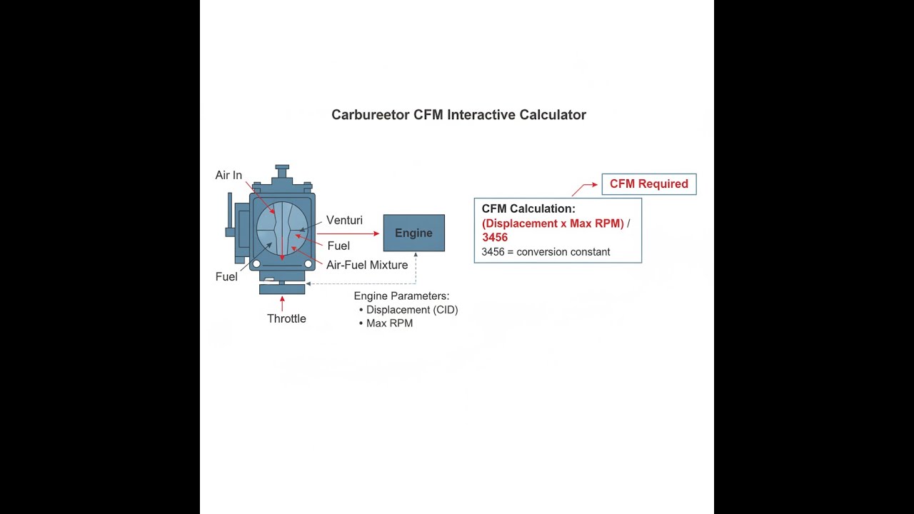
Carburetor Airflow System Diagram

How to Use This Calculator
- Select your calculation mode from the dropdown — choose from CFM required, displacement, RPM, volumetric efficiency, horsepower estimate, or sizing recommendation.
- Enter your engine displacement in cubic inches (CID), your maximum RPM, and your estimated volumetric efficiency percentage.
- If your selected mode requires a CFM rating, target horsepower, or application type, fill in those fields as they appear.
- Click Calculate to see your result.
Carburetor CFM Calculator
Carburetor CFM Interactive Visualizer
See how engine displacement, RPM, and volumetric efficiency combine to determine carburetor airflow requirements. Watch the air velocity visualization change as you adjust parameters to understand why proper CFM sizing matters for throttle response and peak power.
CFM REQUIRED
473 CFM
EST. HORSEPOWER
285 HP
CARB SIZE
500 CFM
FIRGELLI Automations — Interactive Engineering Calculators
Carburetor CFM Equations
Use the formula below to calculate carburetor CFM required for your engine.
Primary CFM Calculation
CFM = (CID × RPM × ηv) / 3456
Where:
CFM = Carburetor airflow requirement (cubic feet per minute)
CID = Engine displacement (cubic inches)
RPM = Maximum engine speed (revolutions per minute)
ηv = Volumetric efficiency (decimal, typically 0.80-0.95)
3456 = Conversion constant (2 revolutions per cycle × 1728 in³/ft³)
Volumetric Efficiency
ηv = (CFM × 3456) / (CID × RPM)
Solving for volumetric efficiency when CFM and engine parameters are known
Horsepower Estimation
HP ≈ (CFM × 60 × ρair) / (BSFC × (AFR + 1))
Where:
ρair = Air density at sea level (0.0765 lb/ft³)
BSFC = Brake specific fuel consumption (typically 0.45-0.55 lb/hp-hr)
AFR = Air-fuel ratio (typically 12.5-13.5:1 at peak power)
Maximum Supported RPM
RPMmax = (CFM × 3456) / (CID × ηv)
Determines the maximum engine speed a given carburetor can support without airflow limitation
Simple Example
A 350 CID V8 engine spinning to 5500 RPM with 85% volumetric efficiency:
CFM = (350 × 5500 × 0.85) / 3456 = 472.5 CFM
Street sizing (90%): 425 CFM — a 450 CFM carburetor works well.
Race sizing (110%): 520 CFM — a 600 CFM carburetor gives headroom with no restriction.
Theory & Practical Applications
Fundamental Principles of Carburetor Airflow
The carburetor CFM calculation derives from the fundamental relationship between engine displacement, operating speed, and volumetric efficiency. A four-stroke internal combustion engine completes one full cycle (intake, compression, power, exhaust) every two crankshaft revolutions, meaning each cylinder draws in fresh air-fuel mixture once per two revolutions. The theoretical displacement volume per minute equals (CID × RPM)/2, but this must be converted from cubic inches to cubic feet by dividing by 1728 in³/ft³, yielding the constant 3456 in the denominator.
Volumetric efficiency (ηv) represents the actual airflow as a percentage of the theoretical maximum displacement volume. Stock engines with restrictive intake manifolds, conservative camshaft profiles, and emissions equipment typically achieve 75-85% volumetric efficiency at peak torque RPM. Performance engines with ported cylinder heads, optimized intake runner lengths, and aggressive camshaft timing can reach 90-100% efficiency. Race engines with tuned intake systems and minimal restrictions occasionally exceed 100% efficiency through ram-air effects and resonance tuning at specific RPM ranges.
The conversion constant 3456 accounts for both the four-stroke cycle (dividing by 2) and the cubic inch to cubic foot conversion (dividing by 1728): 2 × 1728 = 3456. This constant applies universally to naturally aspirated four-stroke engines regardless of configuration (inline, V, flat). Two-stroke engines would use 1728 instead of 3456 since they complete a power cycle every revolution rather than every two revolutions.
Carburetor Selection Strategies Across Applications
Street-driven vehicles benefit from carburetors sized 10-15% below calculated maximum CFM requirements. An undersized carburetor maintains higher air velocity through the venturi at part-throttle conditions, improving fuel atomization and throttle response during daily driving. The vacuum-actuated secondary throttle plates on street carburetors open progressively based on engine demand rather than throttle position, preventing bog conditions when the driver opens the throttle rapidly from low RPM.
Performance street engines operating frequently at wide-open throttle require carburetor sizing closer to calculated CFM values, typically within 5% of the theoretical requirement. Mechanical secondary throttle linkages provide instantaneous secondary opening for aggressive driving, though proper tuning of secondary spring tension prevents stumble. These applications prioritize peak power delivery over fuel economy and part-throttle drivability.
Competition engines demand carburetors sized 5-10% above calculated CFM to avoid airflow restriction at maximum RPM. Race carburetors incorporate annular discharge boosters that improve mixture distribution across the RPM range, high-flow venturi designs that minimize pressure drop, and adjustable metering blocks that enable precise fuel delivery tuning. Dominator-style carburetors with 4500-series flanges provide maximum airflow capacity for large-displacement engines exceeding 500 cubic inches.
An often-overlooked consideration involves the relationship between carburetor CFM and air velocity through the venturi. Optimal venturi velocity ranges from 240-280 ft/s at peak power RPM. Velocities below 200 ft/s result in poor fuel atomization and weak mixture signals, while velocities exceeding 320 ft/s create excessive pressure drop and restrict airflow. The venturi area must balance maximum flow capacity against maintaining adequate velocity across the operating range.
Altitude Corrections and Environmental Factors
Air density decreases approximately 3% per 1000 feet of elevation gain due to reduced atmospheric pressure. A carburetor sized correctly for sea-level operation becomes effectively oversized at high altitude because the engine draws less air mass per revolution despite maintaining the same volumetric displacement. This explains why naturally aspirated engines lose approximately 3% horsepower per 1000 feet of elevation gain — the carburetor delivers excess fuel relative to available oxygen.
Main jet sizing must be reduced with increasing altitude to maintain proper air-fuel ratios. As a practical guideline, reduce main jet size by 4-6% per 3000 feet of elevation gain. Alternatively, lean the mixture by 2-4% when relocating a vehicle from sea level to 5000 feet altitude. Ignition timing often requires minor advancement at altitude (1-2 degrees) because the lower combustion chamber pressure reduces detonation tendency.
Temperature effects compound altitude corrections. Hot air reduces density beyond the pressure-based altitude correction alone. A standard day at sea level (59°F, 29.92 inHg) provides baseline air density of 0.0765 lb/ft³. On a hot day (95°F), density drops to approximately 0.0710 lb/ft³, equivalent to operating at 2000 feet elevation. Carburetor tuning must account for seasonal temperature variations, particularly in performance applications where air-fuel ratio precision affects engine longevity.
Worked Engineering Example: Small Block V8 Carburetor Sizing
Scenario: A performance engine builder is preparing a 383 cubic inch stroker small block Chevrolet for street/strip use. The engine features aluminum cylinder heads with 2.02" intake valves, a hydraulic roller camshaft with 0.525" lift and 230° duration at 0.050" lift, and a single-plane intake manifold. The engine will operate to 6200 RPM regularly during track days but must remain streetable for occasional cruise nights. Target volumetric efficiency with this combination is estimated at 88% based on similar builds.
Given:
- Engine displacement: CID = 383 in³
- Maximum operating RPM: RPM = 6200 rev/min
- Estimated volumetric efficiency: ηv = 0.88
- Application type: Street/strip (dual-purpose)
- Target: Determine optimal carburetor CFM rating
Step 1: Calculate theoretical maximum CFM requirement
Using the primary CFM equation:
CFM = (CID × RPM × ηv) / 3456
CFM = (383 × 6200 × 0.88) / 3456
CFM = (2,094,640) / 3456
CFM = 606.0 ft³/min
Step 2: Evaluate sizing factors for dual-purpose application
Street-oriented sizing factor: 0.90 × 606.0 = 545.4 CFM (prioritizes low-end response)
Race-oriented sizing factor: 1.05 × 606.0 = 636.3 CFM (prioritizes peak power)
Balanced dual-purpose sizing: 0.98 × 606.0 = 593.9 CFM (compromise approach)
Step 3: Select from available carburetor ratings
Standard performance carburetor offerings include 600, 650, 750, and 850 CFM ratings. The calculated requirement of 606 CFM falls directly between the 600 and 650 CFM options. For this application:
- 600 CFM: Provides 99% of calculated requirement, excellent street manners, slight restriction at 6200 RPM
- 650 CFM: Provides 107% of calculated requirement, no restriction, slightly larger throttle bores may reduce part-throttle velocity
Step 4: Assess venturi velocity at peak power
For a 600 CFM carburetor with 1.375" primary venturi diameter (standard Holley 4160 configuration):
Primary venturi area = π × (1.375/2)² = 1.485 in² (both primaries)
Total venturi area (4 barrels) = 2 × 1.485 = 2.970 in² = 0.0206 ft²
Velocity = CFM / Area = 606 / 0.0206 = 29,417 ft/min = 490 ft/s
This velocity is too high, indicating the calculation should account for all four venturis operating simultaneously. Correcting:
All four venturis combined area ≈ 5.94 in² = 0.0412 ft²
Velocity = 606 / 0.0412 = 14,709 ft/min = 245 ft/s
This falls within the optimal 240-280 ft/s range for good fuel atomization without excessive restriction.
Step 5: Final recommendation and tuning considerations
Recommended carburetor: 650 CFM vacuum secondary 4-barrel (mechanical secondary acceptable for track-focused use)
Initial main jet sizing: Start 4-6% rich, tune based on air-fuel ratio readings at wide-open throttle
Expected results:
- Peak power airflow limitation: None up to 6400 RPM
- Part-throttle drivability: Excellent with vacuum secondaries
- Fuel economy: Moderate (12-15 mpg mixed driving typical for this displacement/camshaft combination)
If the owner prioritizes track performance and accepts reduced street manners, upgrading to a 750 CFM mechanical secondary carburetor provides headroom for future engine modifications (cylinder head porting, more aggressive camshaft) without carburetor-induced airflow restriction. However, the larger throttle bores (1.5625" primaries vs. 1.4375") reduce air velocity at part throttle, potentially causing throttle response delays and mixture distribution issues below 3000 RPM.
Carburetor CFM in Modern Engine Management
While electronic fuel injection has replaced carburetors in modern production vehicles, the CFM calculation principles remain relevant for throttle body sizing, intake manifold design validation, and forced induction system planning. Mass airflow sensors in fuel-injected engines measure actual airflow in grams per second, which converts to CFM for comparison with theoretical displacement calculations. Significant deviations between measured and calculated airflow indicate restrictions in the intake system, valve train inefficiencies, or camshaft timing issues.
Forced induction systems (turbochargers and superchargers) alter volumetric efficiency calculations because boost pressure increases air density. An engine operating at 14.7 psi boost (1 bar, or twice atmospheric pressure) effectively doubles its volumetric efficiency, requiring twice the CFM capacity of the same engine naturally aspirated. Carburetor sizing for boosted applications must account for both the increased airflow demand and the need for enrichment under boost conditions to prevent detonation.
Frequently Asked Questions
Free Engineering Calculators
Explore our complete library of free engineering and physics calculators.
Browse All Calculators →🔗 Explore More Free Engineering Calculators
- Pneumatic Valve Flow Coefficient (Cv) Calculator
- Reynolds Number Calculator — Laminar or Turbulent
- Hydraulic Pump Flow Rate Calculator
- Orifice Flow Rate Calculator
- Pump Horsepower Calculator
- Mach Number Calculator
- Stokes Law Calculator
- Water Hammer Calculator — Pressure Surge in Pipes
- Bolt Torque Calculator — Preload and Clamp Force
- Flow Rate Converter — GPM LPM CFM
About the Author
Robbie Dickson — Chief Engineer & Founder, FIRGELLI Automations
Robbie Dickson brings over two decades of engineering expertise to FIRGELLI Automations. With a distinguished career at Rolls-Royce, BMW, and Ford, he has deep expertise in mechanical systems, actuator technology, and precision engineering.
Need to implement these calculations?
Explore the precision-engineered motion control solutions used by top engineers.


