Geotechnical failures — slope collapses, foundation bearing failures, retaining wall overturns — almost always come down to one thing: the soil's shear strength was lower than the applied stress. Use this Shear Strength Mohr-Coulomb Calculator to calculate shear strength, effective stress parameters, normal stress, friction angle, cohesion, and factor of safety using cohesion, friction angle, normal stress, and pore water pressure. It's essential for slope stability analysis, shallow foundation design, and retaining wall engineering. This page includes the governing equations, a worked example, the theory behind effective vs. total stress analysis, and an FAQ.
What is Shear Strength (Mohr-Coulomb)?
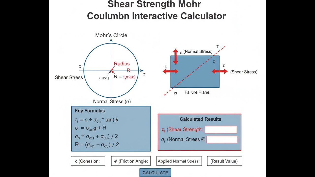
Shear strength is the maximum stress a soil can resist before it slides or shears along a failure plane. The Mohr-Coulomb model says that strength depends on 2 things: cohesion (how sticky the soil is) and friction (how much resistance increases with pressure pushing the surfaces together).
Simple Explanation
Think of soil like a pile of sand with a bit of glue mixed in. The glue holds it together even with no weight on it — that's cohesion. The heavier the load pressing down, the harder it is to slide the soil apart — that's friction. The Mohr-Coulomb equation just adds those 2 contributions together to give you the total shear strength.
📐 Browse all 1000+ Interactive Calculators
Mohr-Coulomb Diagram

How to Use This Calculator
- Select your Calculation Mode from the dropdown — choose what you want to solve for (shear strength, cohesion, friction angle, etc.).
- Enter the required soil parameters for your chosen mode — cohesion (kPa), friction angle (degrees), normal stress (kPa), pore water pressure (kPa), or applied/available shear stress as prompted.
- Check your units — all stress inputs are in kPa and the friction angle is in degrees.
- Click Calculate to see your result.
Interactive Shear Strength Calculator
Mohr-Coulomb Shear Strength Interactive Visualizer
Visualize how cohesion and friction angle combine to create the failure envelope, and see how normal stress affects shear strength. Watch the Mohr circle move toward failure as you adjust soil parameters and loading conditions.
SHEAR STRENGTH
72.3 kPa
FACTOR OF SAFETY
1.61
STATUS
SAFE
FIRGELLI Automations — Interactive Engineering Calculators
Governing Equations
Use the formula below to calculate shear strength using the Mohr-Coulomb failure criterion.
Mohr-Coulomb Failure Criterion
τ = c + σ tan(φ)
τ = Shear strength (kPa or psf)
c = Cohesion intercept (kPa or psf)
σ = Normal stress on the failure plane (kPa or psf)
φ = Angle of internal friction (degrees)
Use the formula below to calculate effective shear strength accounting for pore water pressure.
Effective Stress Formulation
τ = c′ + σ′ tan(φ′)
σ′ = σ - u
c′ = Effective cohesion (kPa or psf)
σ′ = Effective normal stress (kPa or psf)
φ′ = Effective angle of internal friction (degrees)
u = Pore water pressure (kPa or psf)
Use the formula below to calculate factor of safety against shear failure.
Factor of Safety
FS = τf / τmobilized
FS = Factor of safety (dimensionless)
τf = Shear strength at failure (kPa or psf)
τmobilized = Applied or mobilized shear stress (kPa or psf)
Simple Example
A soil sample has cohesion c = 10 kPa, friction angle φ = 30°, and normal stress σ = 100 kPa.
τ = c + σ tan(φ) = 10 + 100 × tan(30°) = 10 + 57.74 = 67.74 kPa
That's the shear strength at failure on that plane. If the applied shear stress is 45 kPa, the factor of safety is 67.74 / 45 = 1.51 — just meeting the typical minimum for permanent works.
Theory & Engineering Applications
The Mohr-Coulomb failure criterion represents one of the most enduring and widely applied theories in geotechnical engineering, formulated in the 1770s by Charles-Augustin de Coulomb and later extended by Christian Otto Mohr. This criterion describes the linear relationship between shear strength and normal stress for soils and rocks, providing the foundation for slope stability analysis, bearing capacity calculations, retaining wall design, and underground excavation support.
Fundamental Principles of the Mohr-Coulomb Model
The Mohr-Coulomb criterion posits that shear failure occurs along a plane when the shear stress reaches a critical value determined by two independent material properties: cohesion and friction angle. Cohesion represents the inherent shear strength at zero normal stress, attributed to cementation, electrostatic forces between clay particles, or apparent cohesion from suction in unsaturated soils. The friction angle quantifies the increase in shear strength with increasing normal stress, reflecting particle interlocking, surface roughness, and mineral hardness.
The linear failure envelope intercepts the vertical axis at the cohesion value and slopes upward at an angle equal to the friction angle. This graphical representation on the Mohr diagram — where circles represent stress states and the failure envelope defines the limiting condition — provides intuitive visualization of soil behavior under various loading conditions. Stress states plotting below the envelope represent stable conditions, while those touching the envelope indicate incipient failure.
Effective Stress versus Total Stress Analysis
A critical distinction in geotechnical practice involves effective stress versus total stress analysis. Terzaghi's principle of effective stress states that soil behavior is controlled by the effective stress (σ′ = σ - u), where the total stress is reduced by pore water pressure. For drained conditions — where excess pore pressures dissipate during loading — effective stress parameters (c′ and φ′) govern behavior. In undrained conditions typical of saturated clays loaded rapidly, total stress parameters (cu and φu) apply, with φu often assumed to be zero for fully saturated clays.
The distinction becomes particularly important in slope stability analysis following rapid drawdown of reservoirs, earthquake loading, or construction of embankments on soft clay foundations. Engineers must select appropriate parameters based on drainage conditions, loading rate, and soil permeability. Misapplication of total stress parameters in long-term stability analysis or effective stress parameters for rapid loading can lead to unconservative designs and catastrophic failures.
Limitations and Non-Linear Behavior
While the Mohr-Coulomb criterion provides excellent predictions for many practical problems, real soil behavior exhibits important departures from the linear model. At low confining stresses typical of shallow foundations, the failure envelope for many soils curves upward, providing higher shear strength than predicted by the linear model. Conversely, at high confining pressures encountered in deep excavations or beneath tall embankments, particle crushing and pore collapse cause the envelope to curve downward.
Heavily overconsolidated clays demonstrate peak strength significantly exceeding residual strength due to bonding and particle structure developed during previous loading history. Post-peak softening and progressive failure can occur as local stress concentrations cause sequential failure of soil elements, mobilizing lower residual strengths along the failure surface. This behavior necessitates careful consideration in slope stability analysis, where brittle failures may occur with less warning than predicted by peak strength parameters.
Worked Example: Embankment Slope Stability
Consider a highway embankment constructed on a foundation of normally consolidated clay. The embankment is 8.5 meters high with side slopes of 3H:1V (horizontal to vertical). At a critical failure plane located 2.7 meters below the toe of the slope, soil testing indicates effective cohesion c′ = 12.3 kPa and effective friction angle φ′ = 24.7 degrees. The total normal stress at this depth is calculated from overburden as σ = 167.4 kPa. Piezometer measurements indicate pore water pressure u = 38.6 kPa at this location.
Step 1: Calculate Effective Normal Stress
Using Terzaghi's effective stress principle:
σ′ = σ - u = 167.4 - 38.6 = 128.8 kPa
Step 2: Calculate Available Shear Strength
Applying the Mohr-Coulomb criterion with effective stress parameters:
φ′ = 24.7° = 0.4311 radians
tan(φ′) = tan(24.7°) = 0.4592
τf = c′ + σ′ tan(φ′) = 12.3 + (128.8)(0.4592) = 12.3 + 59.15 = 71.45 kPa
Step 3: Determine Mobilized Shear Stress
From slope stability analysis using the method of slices, the mobilized shear stress along this critical surface is calculated as τmob = 48.7 kPa.
Step 4: Calculate Factor of Safety
FS = τf / τmob = 71.45 / 48.7 = 1.467
Interpretation: The factor of safety of 1.47 exceeds the minimum acceptable value of 1.3 for temporary highway embankments but falls below the 1.5 typically required for permanent structures. If groundwater levels rise during heavy rainfall, reducing effective stress, the factor of safety could drop below acceptable limits. The design engineer should consider installing horizontal drainage layers or flattening the slope to 4H:1V to achieve FS = 1.5 or greater for long-term stability.
Applications in Foundation Engineering
The Mohr-Coulomb criterion forms the basis for bearing capacity equations developed by Terzaghi, Meyerhof, and others. For shallow foundations, the ultimate bearing capacity depends on cohesion and friction angle through dimensionless bearing capacity factors that are functions of φ. The general bearing capacity equation incorporates both cohesive and frictional resistance, with the relative contribution of each term depending on soil type and foundation depth.
In pile foundation design, the Mohr-Coulomb model governs shaft friction along the pile-soil interface. Effective stress analysis predicts long-term shaft capacity in driven piles, while total stress analysis applies to immediate loading of piles in clay. The β-method and λ-method for estimating pile shaft friction both derive from Mohr-Coulomb principles, relating shaft friction to vertical effective stress through empirically calibrated coefficients related to the friction angle.
Retaining Wall and Earth Pressure Applications
Lateral earth pressure coefficients for retaining wall design derive directly from Mohr-Coulomb theory through consideration of limiting equilibrium states. Rankine's theory provides active and passive earth pressure coefficients as functions solely of the friction angle, applicable to smooth, vertical walls with horizontal backfill. Coulomb's wedge theory extends this to include wall friction, backfill slope, and wall inclination, requiring iterative solution of the Mohr-Coulomb criterion along a trial failure surface.
The transition from at-rest pressure (K₀ condition) to active pressure requires sufficient wall movement to mobilize the full friction angle along the failure wedge. Typical movements range from 0.001H to 0.004H for active conditions in dense sand, where H represents wall height. Passive pressure mobilization requires substantially greater movement — 0.01H to 0.05H — making passive resistance unsuitable for serviceability-controlled designs where deformations must be minimized.
For comprehensive engineering resources including additional geotechnical calculators for bearing capacity, consolidation settlement, and earth pressure coefficients, visit the complete engineering calculator library.
Practical Applications
Scenario: Foundation Design for Coastal Development
Marcus, a geotechnical engineer at a coastal engineering firm, is designing shallow spread footings for a three-story commercial building on a site with silty clay soils. Laboratory direct shear tests on undisturbed samples yielded effective cohesion c′ = 15.7 kPa and effective friction angle φ′ = 27.3°. At the proposed footing depth of 1.8 meters, the total overburden stress is 34.2 kPa, and seasonal high groundwater creates pore pressure of 8.4 kPa. Using this calculator, Marcus determines the effective normal stress (25.8 kPa) and available shear strength (43.0 kPa). Comparing this to the mobilized shear stress from bearing capacity analysis (28.6 kPa), he calculates a factor of safety of 1.50, meeting the building code requirement of 1.5 for combined dead and live loads. This analysis confirms the footing dimensions are adequate without requiring expensive ground improvement or deeper foundations.
Scenario: Emergency Slope Stabilization After Heavy Rainfall
Jennifer, a municipal engineer responding to a landslide warning along a critical highway corridor, needs to quickly assess slope stability after three days of heavy rainfall saturated the hillside. Previous site investigations documented the residual clay layer with c′ = 8.2 kPa and φ′ = 19.5°. Before the storm, pore pressures averaged 22 kPa, but current piezometer readings show pressures have risen to 47 kPa along the critical failure surface where total stress is 183 kPa. Using the effective stress calculator mode, Jennifer determines that effective stress dropped from 161 kPa to 136 kPa, reducing shear strength from 67.3 kPa to 56.1 kPa. With mobilized shear stress of 53.8 kPa from slope stability software, the factor of safety decreased from 1.25 to 1.04—dangerously close to failure. She immediately recommends closing the highway and installing emergency dewatering wells to lower the groundwater table, potentially preventing a catastrophic slope failure that could cost millions and endanger lives.
Scenario: Retaining Wall Design Optimization
David, a structural engineer designing a 6.2-meter tall cantilever retaining wall for a parking terrace, is optimizing the design to minimize concrete volume while maintaining adequate safety. The granular backfill has cohesion c = 0 kPa (cohesionless) and friction angle φ = 36°. At mid-height of the wall (3.1 meters), the lateral earth pressure coefficient indicates normal stress of 28.7 kPa against the back of the wall. Using this calculator's shear strength mode, David verifies the available shear resistance along the soil-wall interface is 20.9 kPa (assuming wall friction angle δ = 24° = 2φ/3). Comparing this to the applied shear stress from the soil wedge (17.3 kPa), he confirms the factor of safety of 1.21 is acceptable for the temporary construction condition. After backfill compaction and installation of permanent drainage, he will verify the long-term stability using reduced pore pressures, which should increase the factor of safety above 1.5. This analysis allows him to confidently specify wall dimensions without over-designing and wasting concrete.
Frequently Asked Questions
Free Engineering Calculators
Explore our complete library of free engineering and physics calculators.
Browse All Calculators →🔗 Explore More Free Engineering Calculators
About the Author
Robbie Dickson — Chief Engineer & Founder, FIRGELLI Automations
Robbie Dickson brings over two decades of engineering expertise to FIRGELLI Automations. With a distinguished career at Rolls-Royce, BMW, and Ford, he has deep expertise in mechanical systems, actuator technology, and precision engineering.
Need to implement these calculations?
Explore the precision-engineered motion control solutions used by top engineers.


