


FA-MGR-15 Series - Mini Linear Slide Rails
The FA-MGR-15 Series Mini Linear Slide Rail is a compact recirculating-ball guide for applications that need smooth, accurate linear movement in a small installation envelope. The system combines a 15 mm-wide steel rail with a sealed carriage block to support and guide a moving load while limiting unwanted side-to-side play.
As the carriage moves, its recirculating ball bearings are cleaned and lubricated by the end-cap reservoirs. Built-in wipers, seals and rubber end plates help keep contamination away from the ball tracks, supporting quiet operation and a long service life when the rail is mounted and maintained correctly.
Typical uses include automation fixtures, machine guards, sliding panels, equipment trays, sensor or camera positioning, robotics and other compact linear-motion assemblies. This product provides the linear guidance; a separate actuator, lead screw, belt drive or manual mechanism is required to create motion.
Each selected rail length includes one sliding carriage. Length options are 10, 20, 30, 40 and 50 inches.
Specifications
Download the complete FA-MGR-15 dimensional and performance specification sheet.
DOWNLOAD FA-MGR-15 PDF SPEC SHEET| Specification | FA-MGR-15 |
|---|---|
| Maximum stated load | 330 lb (150 kg) |
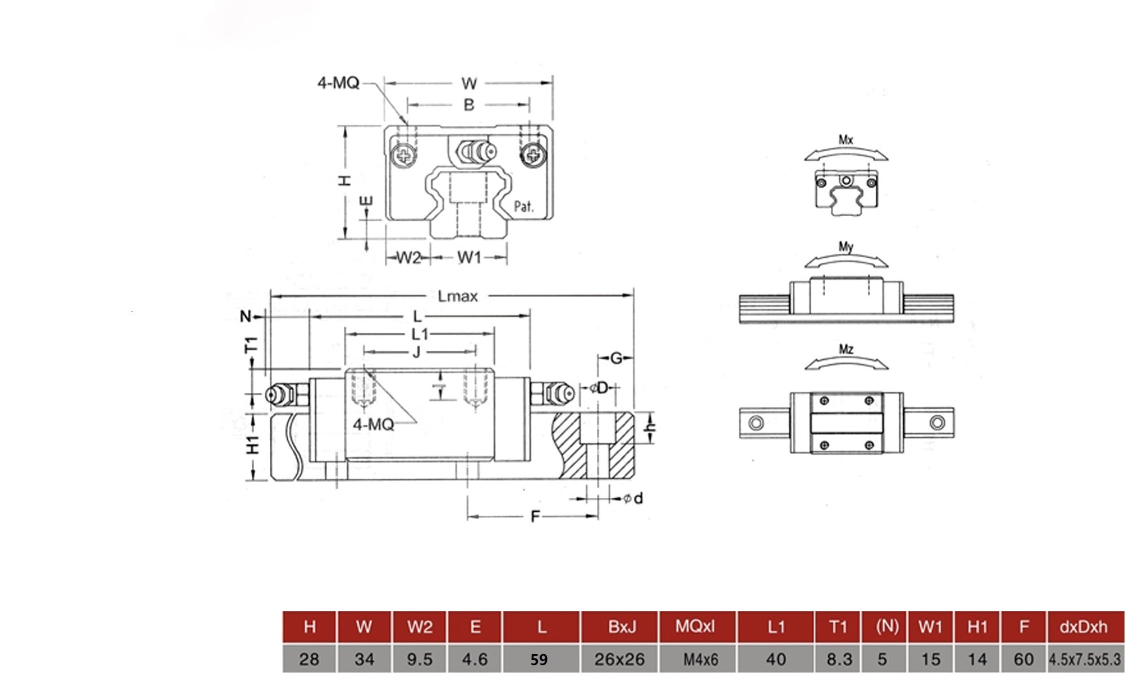
| Assembly height (H) | 28 mm |
| Carriage width (W) | 34 mm |
| Carriage length (L) | 59 mm |
| Carriage mounting-hole pattern (B × J) | 26 × 26 mm |
| Carriage mounting threads | 4 × M4, 6 mm thread depth |
| Carriage reference length (L1) | 40 mm |
| Side offset (W2) | 9.5 mm |
| Vertical offset (E) | 4.6 mm |
| T1 / N dimensions | 8.3 mm / 5 mm |
| Rail width (W1) | 15 mm |
| Rail height (H1) | 14 mm |
| Rail mounting-hole pitch (F) | 60 mm |
| Rail mounting-hole geometry (d × D × h) | 4.5 × 7.5 × 5.3 mm |
Design and Mounting Notes
- Mount the rail to a flat, rigid and fully supported surface. Misalignment or an uneven base can cause binding and shorten bearing life.
- Attach the moving plate or payload using the four M4 carriage holes. Select screw length carefully so the screws engage securely without bottoming out.
- The drawing identifies roll, pitch and yaw moments (Mx, My and Mz). Off-center or overhung loads create these moments even when the payload is below the stated maximum load.
- For wide, cantilevered or high-moment loads, use two parallel rails, additional carriages or both, and verify alignment across the complete travel.
- The 330 lb (150 kg) figure is the stated maximum load. Safe working capacity depends on load direction, shock, vibration, mounting rigidity, carriage spacing and the applied moment; include an appropriate engineering safety factor.
- Keep the rail clean and adequately lubricated. The built-in wipers and seals reduce contamination but do not make the assembly waterproof.
- Do not slide the carriage off the end of the rail unless an appropriate transfer tool is used, because the recirculating balls can be displaced.
Technical Drawing
Linear Bearing resources
Get the complete FA-MGR-15 dimensions, load ratings and mounting information.
DOWNLOAD FA-MGR-15 PDF SPEC SHEETWe created a Blog post with a few Videos to help understand how Linear Bearings work. Click here to go to the article