


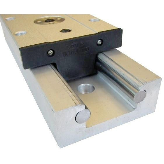


FA-SGR-35 Series - Heavy Duty Linear Bearing Slide Rails
The FA-SGR-35 Series is a heavy-duty linear bearing slide rail for moving supported loads smoothly and accurately along a straight path. Its adjustable carriage runs on GCr15 steel bearings against carbon-steel running rails, providing rigid linear guidance for material-handling equipment, machinery, equipment trays, guards, vehicle and RV storage systems, automation fixtures and other high-load mechanisms.
Each selected rail includes one sliding carriage. Additional FA-SGR-35 carriages are available separately when an application needs more support or greater resistance to off-center loading. This product provides linear guidance only; a separate actuator, lead screw, belt drive, cylinder or manual mechanism is required to create motion.
The carriage preload is adjustable so installers can balance running resistance against unwanted play. Ground datum surfaces on both sides of the rail support accurate alignment. Standard rail lengths are 20, 30, 40, 50, 60 and 84 inches. Rails may be shortened with a suitable abrasive cut-off process, then carefully deburred and cleaned before use.
Specifications
Download the complete FA-SGR-35 dimensional and performance specification sheet.
DOWNLOAD FA-SGR-35 PDF SPEC SHEET| Specification | FA-SGR-35 Series |
|---|---|
| Maximum published compression load | 750 lb (340 kg) |
| Maximum published tension load | 550 lb (249 kg) |
| Maximum published moment, X / Y / Z | 1,320 lb-in (149 N-m) |
| Operating temperature range | -20 to 80 C (-4 to 176 F) |
| Rail lengths | 20, 30, 40, 50, 60 and 84 in |
| Weight | 4.57 lb/ft (approximately 6.80 kg/m) |
| Materials | Aluminum carriage/profile, GCr15 steel bearings and carbon-steel running rails |
| Included | One rail and one sliding carriage |
| Environment | Indoor use; not recommended for outdoor exposure |
Dimensions and Mounting
| Drawing dimension | Value |
|---|---|
| Rail width | 3.50 in (88.9 mm) |
| Carriage overall length | 6.30 in (160.0 mm) |
| Top mounting plate width | 3.93 in (99.8 mm) |
| Carriage body width | 3.23 in (82.0 mm) |
| Rail/body height | 1.38 in (35.1 mm) |
| Top plate thickness | 0.70 in (17.8 mm) |
| Approximate overall assembly height | 2.08 in (52.8 mm) |
| Top mounting-hole longitudinal span | 5.78 in (146.8 mm), with 1.64 / 2.50 / 1.64 in spacing |
| Carriage mounting threads | 4 x [M12 x 1.75], tapped through |
| Preload-adjustment thread callout | M3 x 0.5 |
Design and Mounting Notes
- Mount the rail to a flat, rigid and fully supported surface. Check straightness and parallelism over the complete travel before fully tightening the fasteners.
- Compression and tension ratings describe different load directions. Off-center loads also create roll, pitch and yaw moments, so check both force and moment limits.
- The published ratings are maximum values. Shock, vibration, acceleration, mounting rigidity, carriage spacing and duty profile can reduce safe working capacity; use an appropriate engineering safety factor.
- For wide or cantilevered payloads, use two parallel rails, additional carriages or both. Align paired rails carefully to prevent binding.
- Adjust carriage preload only enough to obtain the required running resistance and remove unwanted play. Excessive preload increases friction and wear.
- If shortening a rail, protect the bearing surfaces from abrasive debris, deburr the cut end and clean the rail thoroughly before reinstalling the carriage.
- Keep the running surfaces clean and suitably lubricated. The assembly is not weatherproof and is not recommended for outdoor exposure.
Technical Drawings

Product Videos
Linear Bearing resources
Get the complete FA-SGR-35 dimensions, load ratings and mounting information.
DOWNLOAD FA-SGR-35 PDF SPEC SHEETWe created a Blog post with a few Videos to help understand how Linear Bearings work. Click here to go to the article
3D Model Downloads (.STEP)
- FA-SGR-35-20 File
- FA-SGR-35-30 File
- FA-SGR-35-40 File
- FA-SGR-35-50 File
- FA-SGR-35-60 File
- FA-SGR-35-84 File
Tutorials