Gear motors are the workhorses of modern automation, powering everything from precision linear actuators to heavy-duty industrial machinery. At the heart of every gear motor lies a fundamental engineering principle that determines its performance characteristics: the gear ratio. A gear ratio is the ratio of input shaft rotations to output shaft rotations, and it determines the trade-off between speed and torque in a gear motor system. This relationship between input and output shaft rotations governs the critical trade-offs between speed and torque that define how a motor performs in real-world applications.
🎥 Video — Understanding Gear Ratios in Gear Motors
Understanding gear ratios isn't merely an academic exercise—it's essential knowledge for anyone designing motion control systems, selecting motors for automation projects, or troubleshooting performance issues. Whether you're building a standing desk mechanism, developing robotic systems with micro actuators, or engineering industrial equipment, the gear ratio you select will fundamentally determine whether your application succeeds or struggles. In this comprehensive guide, we'll demystify gear ratios, explore different gearbox configurations, and provide the practical knowledge you need to make informed decisions for your motion control applications.
"Every gear ratio decision is really a single trade: you're spending output speed to buy output torque, or the other way around. Once an engineer internalizes that the ratio sits directly between input speed and output speed — and that output torque scales with ratio times efficiency — sizing a gear motor stops being guesswork."
— Robbie Dickson, Founder and Chief Engineer of FIRGELLI Automations
What Are Gear Ratios and Why Do They Matter?
A gear ratio represents the relationship between the number of teeth on two meshing gears, or more broadly, the number of input shaft rotations required to produce one complete output shaft rotation. Expressed as a ratio such as 10:1 or 50:1, this simple number has profound implications for motor performance.
When a motor produces rotational force, its native output characteristics—typically high speed with relatively low torque—rarely match the requirements of the application. Gears act as mechanical transformers, converting the motor's high-speed, low-torque output into the speed and force characteristics your application demands. A 100:1 gear ratio means the motor shaft must rotate 100 times to turn the output shaft once, dramatically multiplying torque while proportionally reducing speed.
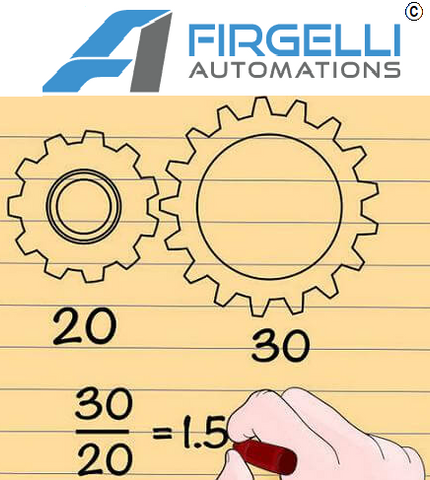
The fundamental equation is straightforward (see Shigley's Mechanical Engineering Design): Gear Ratio = Number of Teeth on Driven Gear ÷ Number of Teeth on Driving Gear. Alternatively, it can be calculated as Input Speed ÷ Output Speed. This relationship creates an inverse proportionality between speed and torque. When you increase the gear ratio to gain torque, you sacrifice speed. When you reduce the gear ratio to increase speed, you lose torque multiplication. There's no free lunch in mechanical engineering—every design choice involves calculated trade-offs.
What types of gearboxes are used in gear motors?
Not all gearboxes are created equal. The internal gear arrangement significantly impacts efficiency, noise levels, size, cost, and load-handling characteristics. Understanding these differences allows you to select the optimal configuration for your specific application requirements.
Spur Gearboxes
Spur gears represent the simplest and most economical gearbox design. These gears feature straight teeth cut parallel to the gear axis and operate on parallel shafts. Their straightforward design makes them easy to manufacture and maintain, which translates to lower costs—an attractive feature for budget-conscious projects or applications where other factors outweigh performance optimization.
However, spur gears come with notable limitations. The straight-tooth design means the entire tooth face engages simultaneously, creating substantial impact forces that generate noise and vibration. This characteristic makes spur gearboxes less suitable for applications requiring quiet operation. Additionally, because load is concentrated on fewer teeth at any given moment, spur gears exhibit higher wear rates and lower efficiency than more sophisticated designs. They typically achieve efficiencies between 85-95% (consistent with AGMA standards for spur gearing), with energy losses manifesting as heat from friction.
Spur gearboxes work well for applications where simplicity, cost, and ease of replacement outweigh concerns about noise, efficiency, or maximum power density. They're commonly found in basic automation tasks, certain consumer products, and applications where gear motors operate intermittently rather than continuously.
Planetary Gearboxes
Planetary gear systems—also called epicyclic gear systems—represent a more sophisticated approach that delivers superior performance in a remarkably compact package. The name derives from their astronomical arrangement: a central sun gear surrounded by multiple planet gears, all contained within an outer ring gear. This configuration resembles planets orbiting a sun, though the mechanical advantages are purely terrestrial.
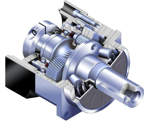
The genius of planetary gears lies in load distribution. Because multiple planet gears share the load simultaneously, stress is distributed across many teeth rather than concentrated on individual gear pairs. This arrangement dramatically increases load capacity, reduces wear, and extends service life. The multiple load paths also enable planetary gearboxes to achieve remarkable power density—delivering high torque in surprisingly small packages.
Planetary gearboxes typically achieve efficiencies between 90-98% (per AGMA efficiency guidelines for epicyclic gearing), significantly higher than spur gear alternatives. The distributed load also reduces vibration and noise, making them ideal for applications requiring smooth, quiet operation. These characteristics explain why planetary gears dominate applications in precision industrial actuators, robotics, medical equipment, and aerospace systems.
The primary drawback of planetary gearboxes is cost. The precision manufacturing required for proper planet gear alignment and load sharing increases production expenses. However, for applications demanding high performance, reliability, and longevity, the investment typically proves worthwhile. Many of the feedback actuators used in precise motion control applications rely on planetary gearboxes for exactly these reasons.
Other Gearbox Configurations
While spur and planetary gears dominate the gear motor landscape, other configurations serve specialized applications:
- Helical Gears: Similar to spur gears but with teeth cut at an angle to the gear axis. The angled teeth engage gradually rather than suddenly, reducing noise and vibration while improving load distribution. The trade-off is a small efficiency penalty and axial thrust forces that require appropriate bearing selection.
- Bevel Gears: Designed to transmit motion between non-parallel shafts, typically at 90-degree angles. These are essential when you need to change the direction of rotation, such as in certain rotary actuator configurations.
- Worm Gears: Provide very high gear ratios (often 20:1 to 300:1) in a single stage with excellent self-locking characteristics. The worm gear's large helix angle creates significant sliding contact, resulting in lower efficiency but the unique property that the output shaft cannot back-drive the input—valuable for holding loads without power.
- Harmonic Drive Gears: Specialized high-precision gearboxes using a flexible spline mechanism to achieve extremely high ratios (50:1 to 300:1) with zero backlash. These excel in applications demanding exceptional positioning accuracy, though at premium cost.
How do you calculate a gear ratio?
While the basic gear ratio calculation is straightforward, understanding how to apply this knowledge in real-world scenarios requires deeper exploration. Let's work through practical examples that illustrate the implications of different ratio selections.
Basic Gear Ratio Calculation
Consider a motor spinning at 3,000 RPM connected to a gearbox with a 50:1 ratio. The output shaft speed becomes:
Output Speed = Input Speed ÷ Gear Ratio = 3,000 RPM ÷ 50 = 60 RPM
Meanwhile, torque multiplication works inversely (accounting for efficiency losses):
Output Torque = Input Torque × Gear Ratio × Efficiency
If the motor produces 0.1 Nm of torque and the gearbox operates at 90% efficiency:
Output Torque = 0.1 Nm × 50 × 0.90 = 4.5 Nm
This example demonstrates the core trade-off: we've reduced speed by a factor of 50 while increasing torque by approximately 45 times (after accounting for efficiency losses). Understanding these relationships allows you to match motor and gearbox combinations to application requirements.
Compound Gear Ratios
Many gearboxes use multiple stages of gears to achieve ratios that would be impractical in a single stage. Each stage contributes to the overall ratio, with the total being the product of individual stage ratios:
Total Gear Ratio = Stage 1 Ratio × Stage 2 Ratio × Stage 3 Ratio... (see Machinery's Handbook for worked examples of multi-stage reduction).
For example, a three-stage planetary gearbox with ratios of 5:1, 4:1, and 3:1 at each stage produces an overall ratio of 5 × 4 × 3 = 60:1. This approach allows gearbox designers to optimize each stage for specific characteristics while achieving high overall ratios in compact packages.
When should you use a high gear ratio for maximum torque?
High gear ratios—typically 50:1 and above, extending to 300:1 or more in some applications—prioritize torque multiplication over speed. These configurations excel in scenarios demanding powerful, controlled motion with substantial load-handling capability.
Advantages of High Gear Ratios
The primary benefit is obvious: massive torque multiplication allows relatively small motors to move heavy loads. A motor producing just 0.5 Nm of torque, paired with a 100:1 gearbox at 95% efficiency, delivers approximately 47.5 Nm at the output shaft—enough to drive substantial mechanical systems.
High gear ratios also provide exceptional control resolution. When 100 motor revolutions produce just one output revolution, the positioning precision achievable with standard motor control becomes 100 times finer. This characteristic proves invaluable in applications like TV lifts and precision positioning systems where smooth, controlled motion matters more than speed.
Additionally, the mechanical advantage of high ratios can protect motors from shock loads and provide inherent load-holding capability, reducing the electrical power required to maintain position under load.
Disadvantages and Considerations
The primary drawback is reduced speed. A motor spinning at 3,000 RPM through a 100:1 gearbox produces just 30 RPM at the output—possibly too slow for applications requiring rapid motion. Multi-stage gearboxes required to achieve very high ratios also introduce cumulative efficiency losses, with each stage consuming a percentage of the input power.
Higher ratios typically mean larger, heavier gearboxes and increased cost. The multiple gear stages required introduce more components that can wear or fail, potentially impacting long-term reliability if not properly designed and lubricated.
When should you use a low gear ratio for high-speed applications?
Low gear ratios—typically 5:1 to 20:1—emphasize speed over torque multiplication. These configurations suit applications where rapid motion takes priority over load-carrying capacity.
When to Use Low Gear Ratios
Low ratios excel in high-speed automation, rapid positioning systems, and applications where loads are relatively light but cycle times are critical. Examples include high-speed pick-and-place operations, certain conveyor systems, and automated packaging equipment.
The reduced mechanical advantage means less torque multiplication, but this limitation proves acceptable when moving light loads. The trade-off delivers faster motion, simpler (often single-stage) gearboxes with higher efficiency, and typically lower cost and reduced size compared to high-ratio alternatives.
Low-ratio gearboxes also experience less cumulative backlash since fewer gear mesh points exist between input and output. This can improve positioning accuracy in applications where backlash rather than resolution limits precision.
Limitations of Low Gear Ratios
The reduced torque multiplication means these systems struggle with heavy loads or high-resistance applications. The motor must work harder, potentially leading to overheating, reduced efficiency, or premature failure if the load exceeds the motor's continuous-duty rating.
Lower torque multiplication also means less mechanical advantage protecting the motor from shock loads or sudden resistance changes. This can increase wear on motor components and reduce system reliability in demanding applications.
How do you select the right gear ratio for an application?
Choosing an optimal gear ratio requires careful analysis of your application requirements. Several factors must be considered simultaneously to arrive at the best solution.
Load Requirements
Start by calculating the torque required at the output shaft. For linear motion applications using components like track actuators or drawer slides, this involves considering the load weight, friction, acceleration forces, and any additional resistance factors. Include a safety margin—typically 25-50% above calculated requirements—to account for variations, aging, and unexpected conditions.
Speed Requirements
Determine the output speed your application demands. Is rapid motion essential, or is controlled, deliberate movement more important? Remember that higher gear ratios reduce speed proportionally, so balance torque needs against speed requirements.
Duty Cycle Considerations
Will your gear motor operate continuously or intermittently? Continuous-duty applications generate more heat and require gearboxes rated for sustained operation with appropriate thermal management. Intermittent operation allows higher peak loads but still requires sizing that prevents cumulative heat buildup.
Precision and Control
Applications requiring precise positioning benefit from higher gear ratios, which provide finer control resolution. However, consider backlash—the small rotational play between meshing gears—which accumulates through multiple gear stages. Planetary gearboxes typically exhibit lower backlash than spur gear alternatives, making them preferable for precision applications with feedback actuators that monitor position.
Environmental Factors
Operating environment influences gearbox selection. Temperature extremes affect lubricant viscosity and material properties. Moisture, dust, or chemical exposure may require sealed gearboxes with appropriate ingress protection ratings. Vibration, shock loads, or continuous operation all impact reliability and service life expectations.
How are gear motors used in linear motion systems?
While gear ratios traditionally describe rotary motion, they play crucial roles in linear motion systems. Many linear actuators incorporate gear motors that convert rotary motion to linear displacement through lead screws, ball screws, or rack-and-pinion mechanisms.
In these applications, the gear ratio works in concert with the mechanical advantage of the linear conversion mechanism. A high-ratio gear motor driving a fine-pitch lead screw can provide exceptional force with precise control—ideal for applications like column lifts or precision positioning stages.
The relationship between rotary and linear motion adds another layer of consideration. Lead screw pitch (the linear distance traveled per revolution) effectively creates an additional "ratio" that must be factored into system design. A 50:1 gear motor driving a 2mm pitch lead screw produces 2mm of linear motion per 50 motor revolutions—extremely fine positioning resolution but very slow linear speed.
What maintenance do gear motors need to last?
Proper gear motor maintenance significantly extends service life and maintains performance. Understanding how gear ratios influence maintenance requirements helps establish appropriate service schedules.
Higher-ratio gearboxes with multiple stages require more frequent lubrication checks since they contain more gear meshes generating friction and heat. Planetary gearboxes, while more efficient, demand proper lubrication to maintain the load-sharing characteristics that make them effective.
Operating conditions matter enormously. Gearboxes running near their maximum rated torque generate more heat and experience faster wear than those operating well within their ratings. Similarly, frequent direction changes or rapid start-stop cycles increase stress compared to steady-state operation.
Monitor for common failure indicators: unusual noise (suggesting gear wear or inadequate lubrication), increased backlash (indicating gear tooth wear), elevated operating temperature, or unexpected resistance. Many modern systems incorporate control boxes that can monitor motor current as an indirect indicator of gearbox condition—rising current under constant load often signals increasing friction from wear or lubrication degradation.
How do gear ratios integrate with motion control systems?
Modern motion control systems must account for gear ratios when programming positioning, velocity, and acceleration profiles. When using Arduino or other microcontroller-based systems, the gear ratio directly affects the relationship between motor steps or encoder counts and actual output position.
For example, a stepper motor with 200 steps per revolution connected through a 50:1 gearbox requires 10,000 steps to complete one output revolution. Control software must account for this relationship to achieve accurate positioning. Similarly, velocity control must factor in the gear ratio—commanding what seems like a modest motor speed might translate to extremely slow output motion with high ratios.
Feedback systems become particularly important in high-ratio applications. While the gear ratio provides fine positioning resolution, it also magnifies any positioning errors from backlash, compliance, or thermal effects. Closed-loop control with position feedback on the output side—common in feedback actuators—compensates for these effects, ensuring commanded positions match actual positions regardless of gear system characteristics.
Frequently Asked Questions
What gear ratio do I need for my application?
The required gear ratio depends on your specific torque and speed requirements. Calculate the torque needed at the output shaft based on your load, friction, and acceleration requirements. Then determine your motor's available torque and divide the required output torque by the motor torque (accounting for gearbox efficiency, typically 85-95% for spur gears or 90-98% for planetary gears) to find the minimum gear ratio. Balance this against your speed requirements—higher ratios provide more torque but reduce output speed proportionally. For most applications, ratios between 20:1 and 100:1 provide a good balance, though specialized applications may require anything from 5:1 to 300:1 or higher.
What's the difference between planetary and spur gears, and which should I choose?
Spur gears are simpler and more economical, featuring straight teeth on parallel shafts. They work well for budget-conscious applications where noise and efficiency aren't critical concerns. Planetary gears distribute load across multiple planet gears, providing superior torque capacity, higher efficiency (90-98% vs. 85-95%), quieter operation, and more compact packaging. Choose spur gears for cost-sensitive applications with intermittent operation and modest performance demands. Select planetary gears for continuous-duty applications, precision positioning, high torque density requirements, or when quiet operation matters. The higher initial cost of planetary gearboxes often pays off through better performance and longer service life.
Can I use multiple gear motors together to increase torque?
Yes, but synchronization is critical. Multiple gear motors can drive a common output shaft or load, effectively adding their torque contributions together. However, without proper synchronization, motors may fight each other, causing premature wear, efficiency losses, and potential damage. Use electronic synchronization through a coordinated control box or mechanical synchronization through coupled shafts. Ensure motors are identically specified and that load is distributed evenly. For applications requiring substantial force, consider a single larger gear motor or higher gear ratio rather than multiple smaller units, as this typically provides simpler, more reliable operation.
How does backlash affect performance, and how can I minimize it?
Backlash is the small amount of rotational play between meshing gear teeth, manifesting as "slop" when reversing direction. High-ratio gearboxes with multiple stages accumulate backlash from each gear mesh, potentially degrading positioning accuracy. Backlash primarily affects applications requiring precise positioning or frequent direction changes. Minimize backlash by selecting planetary gearboxes (which typically exhibit less backlash than spur gears), specifying anti-backlash or pre-loaded gear designs for critical applications, using closed-loop control with position feedback on the output side, or implementing software compensation that accounts for expected backlash in motion profiles. For the highest precision requirements, consider harmonic drive gearboxes, which can achieve near-zero backlash through their unique flex-spline design.
What maintenance do gear motors require?
Regular maintenance significantly extends gear motor life. Check and replenish lubrication according to manufacturer recommendations—typically every 6-12 months for continuous-duty applications or annually for intermittent use. Monitor operating temperature, as elevated temperatures suggest excessive load, inadequate lubrication, or impending failure. Listen for unusual noises indicating gear wear, misalignment, or bearing problems. Inspect mounting brackets and mechanical connections for looseness or wear. For critical applications, monitor motor current draw—gradual increases under constant load indicate rising friction from gearbox wear or lubrication degradation. Replace gearbox oil or grease completely at intervals specified by the manufacturer, typically every 2-5 years depending on operating conditions. Sealed gearboxes often use lifetime lubrication and require no maintenance until end-of-life, though monitoring performance indicators remains important.
How do I calculate the output speed and torque from a gear ratio?
Calculate output speed by dividing the input speed by the gear ratio: Output Speed (RPM) = Input Speed (RPM) ÷ Gear Ratio. For example, a motor running at 1,500 RPM through a 30:1 gearbox produces 1,500 ÷ 30 = 50 RPM at the output. Calculate output torque by multiplying input torque by the gear ratio and efficiency: Output Torque = Input Torque × Gear Ratio × Efficiency. For instance, a motor producing 0.2 Nm through a 50:1 planetary gearbox at 95% efficiency yields 0.2 × 50 × 0.95 = 9.5 Nm output torque. Always account for efficiency losses—typically 85-95% for spur gears and 90-98% for planetary gears. These calculations help match motor and gearbox combinations to your application's specific speed and torque requirements.
What happens if I choose the wrong gear ratio?
Selecting an incorrect gear ratio leads to poor performance or premature failure. Too low a ratio (insufficient torque multiplication) causes the motor to struggle under load, potentially stalling, overheating, or suffering premature failure from continuous operation beyond its rated capacity. The system may also exhibit poor control, unable to hold position under load or maintain consistent speed. Too high a ratio produces excessive torque but insufficient speed, making the system frustratingly slow and potentially wasting energy. Very high ratios also introduce excessive backlash and may cost more than necessary. When in doubt, err toward slightly higher ratios with corresponding motor sizing adjustments, as this typically provides more controllable operation and better load-holding characteristics, though you'll sacrifice some speed. Always verify your calculations and include appropriate safety margins—typically 25-50% above calculated requirements—to account for variations and unexpected conditions.


