Synchronizing Multiple Linear Actuators: Arduino vs. Integrated Control Solutions
When automating projects that require precise, synchronized motion across multiple linear actuators, engineers and hobbyists face a fundamental choice: build a custom control system from scratch or leverage an integrated solution. This decision impacts not only the initial setup complexity but also the long-term reliability, expandability, and maintenance requirements of your motion control system.
Synchronization is critical in applications ranging from adjustable workbenches and TV lifts to industrial machinery and automated access platforms. Without proper synchronization, actuators operating at slightly different speeds will quickly fall out of alignment, causing mechanical binding, uneven loads, premature wear, and potential system failure. The challenge becomes even more pronounced when actuators carry significant loads or operate over extended stroke lengths where even minor speed variations compound into substantial positional errors.
This comprehensive guide explores two distinct approaches to actuator synchronization: a hands-on Arduino-based solution using the Uno R3 microcontroller paired with high-current motor drivers, and FIRGELLI's purpose-built FCB-1 controller. We'll examine the technical requirements, wiring configurations, operational principles, and practical considerations for each method, enabling you to select the approach that best aligns with your technical capabilities, project requirements, and performance expectations.
Understanding Actuator Synchronization Requirements
Before diving into specific implementation methods, it's essential to understand what synchronization actually means in the context of linear actuators and why it presents technical challenges. Synchronization requires multiple actuators to maintain identical positions throughout their stroke range, typically within tolerances of 1-5mm depending on the application.
The fundamental challenge stems from the fact that no two electric motors are perfectly identical. Manufacturing tolerances, bearing friction variations, load distribution differences, and even temperature effects cause actuators to operate at slightly different speeds under identical voltage inputs. A 2-3% speed variation—barely noticeable in isolation—translates to significant positional differences over time. In a 12-inch stroke actuator, a 3% speed difference results in nearly half an inch of misalignment by the end of travel.
Effective synchronization solutions employ closed-loop feedback control, constantly monitoring the position of each actuator and making real-time speed adjustments to maintain alignment. This requires three critical components: position feedback sensors (Hall effect sensors or optical encoders), a controller capable of processing feedback signals and calculating corrections, and motor drivers with sufficient power handling and speed control capability to implement those corrections.
Method 1: Arduino Uno R3 with High-Current Motor Drivers
The Arduino-based approach offers maximum flexibility and serves as an excellent learning platform for understanding motion control fundamentals. This method is particularly well-suited for engineers and advanced hobbyists who want complete control over synchronization algorithms, enjoy the challenge of system integration, or require custom functionality beyond standard synchronized motion.
Required Components and Specifications
Building an Arduino-based synchronization system requires careful component selection to ensure compatibility and adequate performance. Here's what you'll need:
- Arduino Uno R3: The microcontroller brain of the system, responsible for reading feedback sensors, executing synchronization algorithms, and commanding motor drivers. The Uno R3 provides sufficient processing power and I/O pins for controlling two actuators with basic synchronization logic.
- IBT-2 High-Current Motor Drivers: One driver per actuator, capable of handling 43A peak current and operating at voltages up to 27V. These H-bridge motor controllers amplify the Arduino's low-current PWM signals into the high-current output required by linear actuators, which typically draw 3-10A under load.
- Bullet Actuators with Built-in Hall Sensors: Feedback actuators that provide position data through pulse outputs. Hall effect sensors generate approximately 10-12 pulses per millimeter of travel, enabling precise position monitoring.
- Rocker Switch: Provides manual extend/retract control for the synchronized actuator pair.
- Emergency Stop Button: Critical safety component that immediately cuts power to actuators, preventing equipment damage or injury in fault conditions.
- 5V Power Supply: Dedicated supply for the Arduino, typically a USB connection or regulated wall adapter providing at least 500mA.
- 12V DC Power Supply: Main power source for the actuators, rated for continuous current draw of your specific actuator models plus 20-30% headroom. For two actuators drawing 5A each, a 12V 12-15A supply is recommended.
Wiring Configuration and Connections
Proper wiring is essential for reliable operation and safety. The system architecture separates logic-level control (Arduino) from high-current motor power (IBT-2 drivers) while maintaining common ground references. Follow this detailed connection guide:
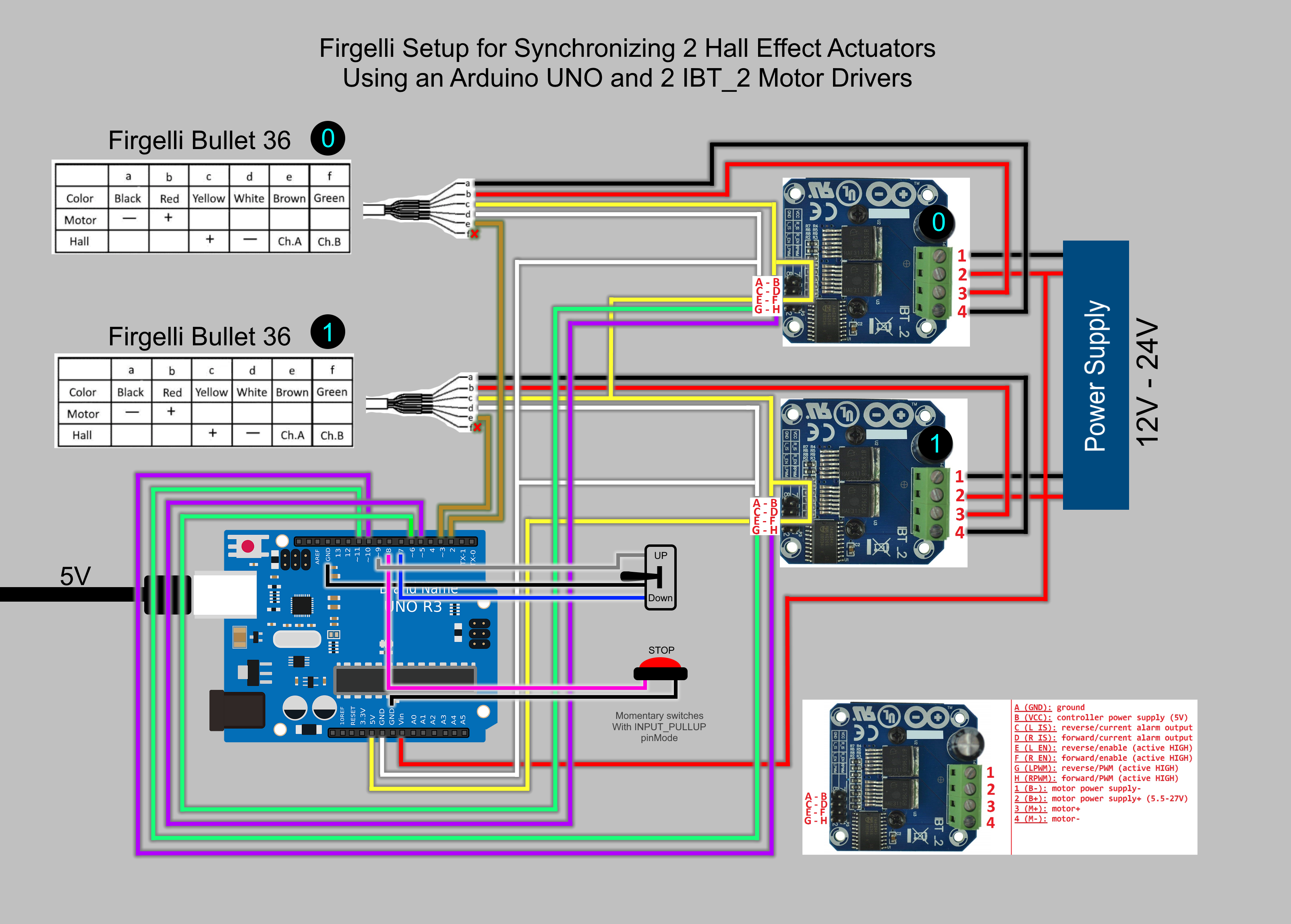
Actuator to Motor Driver Connections: Each actuator's motor wires connect to the output terminals of its dedicated IBT-2 driver. The polarity determines extension/retraction direction—if the actuator moves backward when commanded forward, simply reverse these two wires. Connect the Hall sensor signal wire (typically yellow or white) to the Arduino's digital input pins, with the sensor power and ground connecting to the Arduino's 5V and GND pins respectively.
Arduino to Motor Driver Interface: The Arduino controls each IBT-2 driver through three connections: R_PWM (forward direction speed control), L_PWM (reverse direction speed control), and R_EN/L_EN (enable pins). Connect Arduino PWM-capable digital pins (typically pins 3, 5, 6, 9, 10, 11) to the driver's PWM inputs. Ensure all grounds are common—connect the Arduino GND to both motor driver ground terminals.
Control Interface Wiring: The rocker switch connects to Arduino digital inputs configured with internal pull-up resistors, providing extend and retract commands. The emergency stop button should interrupt the main power supply to the motor drivers, providing a hardware-level safety cutoff independent of the Arduino's logic.
Power Distribution: Power the Arduino through its barrel jack or USB port with a regulated 5V supply. Connect the 12V power supply to the Vcc and GND terminals on both IBT-2 drivers. Use wire gauges appropriate for the current—14 AWG or heavier for the 12V main power distribution, 22-24 AWG for logic-level connections.
Programming Logic and Operation
The Arduino sketch implements a real-time synchronization algorithm that continuously monitors position feedback and adjusts motor speeds accordingly. Access the complete code through the provided link in the original article, but understanding the operational logic helps with troubleshooting and customization.
The synchronization algorithm operates on a simple but effective principle: the Arduino maintains a running count of Hall sensor pulses for each actuator, representing their respective positions. During motion, it compares these pulse counts at regular intervals (typically every 10-50 milliseconds). When a position discrepancy exceeds a defined threshold—usually 3-5 pulses, representing less than 0.5mm—the controller reduces the PWM duty cycle to the faster actuator, effectively slowing it down until the slower actuator catches up.
This approach works because the Hall sensors in bullet actuators generate consistent pulse outputs proportional to linear travel. Each pulse represents a fixed distance of movement, typically 0.08-0.1mm. By counting pulses from the starting position, the Arduino knows the exact position of each actuator at any moment. The controller doesn't try to speed up the slower actuator—doing so might exceed safe current limits or cause binding. Instead, it slows the faster unit, ensuring synchronized motion without risking overload conditions.
The code also handles direction control, reading the rocker switch inputs to determine whether actuators should extend or retract, and implements software limits to prevent over-extension based on maximum pulse counts corresponding to the actuators' full stroke length.
Advantages and Limitations of the Arduino Approach
The Arduino method offers distinct benefits for certain users and applications. Complete control over the synchronization algorithm allows customization for specific requirements—adjusting sync tolerance, implementing acceleration/deceleration ramps, or integrating additional sensors and displays. The system is highly educational, providing hands-on experience with feedback control, PWM motor driving, and embedded programming. Component costs are relatively low, and the modular architecture facilitates troubleshooting and component replacement.
However, this approach also presents challenges. System integration requires solid understanding of electronics, careful attention to wiring details, and debugging skills when issues arise. The Arduino's processing limitations become apparent when attempting to control more than two actuators or implementing sophisticated control algorithms. The IBT-2 drivers, while powerful, are bare boards requiring protective enclosures and proper heat management—they can dissipate 20-30W under heavy loads, necessitating heat sinks or forced air cooling. The system lacks safety features like built-in current limiting, over-temperature protection, or fault diagnostics unless explicitly programmed.
Method 2: FIRGELLI FCB-1 Integrated Controller
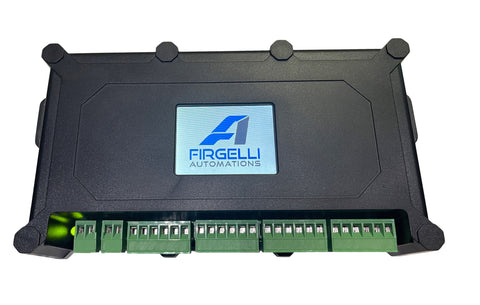
For users prioritizing reliability, ease of installation, and professional-grade performance, the FIRGELLI FCB-1 represents a purpose-engineered alternative. This control box integrates all components required for multi-actuator synchronization into a single, compact unit with intuitive programming through a built-in touchscreen interface.
Key Features and Technical Capabilities
The FCB-1 controller incorporates sophisticated motion control capabilities in a user-friendly package designed for reliable, long-term operation in demanding applications:
- Multi-Actuator Synchronization: Controls up to four feedback actuators simultaneously, maintaining synchronization across all channels with position accuracy typically within 1-2mm across the full stroke range.
- Integrated LED Touchscreen: Provides intuitive menu-driven programming for setting stroke limits, adjusting speed, configuring synchronization parameters, and monitoring system status without requiring external computers or programming knowledge.
- Built-in Motor Drivers: High-current H-bridge drivers integrated within the controller eliminate external motor driver requirements, reducing wiring complexity and potential failure points. Each channel handles continuous currents up to 6A with peak capability to 10A.
- Universal Feedback Compatibility: Works with both Hall effect and optical feedback sensors, automatically adapting to sensor type and resolution. Compatible with FIRGELLI's full range of feedback actuators including bullet actuators, track actuators, and industrial actuators.
- Simplified Power Requirements: Single 12V DC power input powers both the controller and all connected actuators, eliminating multiple power supplies and complex distribution schemes.
- Advanced Protection Features: Built-in over-current protection, thermal management, and fault detection safeguard both the controller and actuators from damage due to binding, overload, or wiring faults.
- Memory Presets: Store multiple position presets for automated sequential motion, one-touch positioning, or integration with external automation systems.
Installation and Setup Process
Setting up the FCB-1 controller is straightforward, typically requiring 30-45 minutes for a complete four-actuator installation with programming:
Step 1 - Physical Connections: Connect each actuator's motor wires and feedback sensor cables to the corresponding output ports on the FCB-1. The controller features clearly labeled, color-coded terminals that simplify wiring and prevent incorrect connections. Each actuator port includes motor positive/negative terminals and a feedback sensor connector accommodating both three-wire Hall sensors and four-wire optical encoders.
Step 2 - Power Supply Connection: Connect a 12V DC power supply to the FCB-1's main power input. Size the supply based on the total current draw of all connected actuators—for four actuators rated at 5A each, specify a 12V 25A supply to provide adequate headroom. The controller's internal power distribution eliminates the need for separate actuator power connections.
Step 3 - Initial Configuration: Power on the controller and use the touchscreen interface to configure basic parameters for each actuator channel: stroke length, speed settings, and synchronization group assignments. The menu-driven interface guides users through each setting with clear prompts and real-time feedback. The controller automatically detects feedback sensor types and adjusts its algorithm accordingly.
Step 4 - Calibration and Testing: Run the built-in calibration routine that extends and retracts each actuator through its full stroke, learning end positions and verifying synchronization accuracy. This automated process takes 2-3 minutes per actuator and establishes the reference positions used for all subsequent motion control.
Advantages of the Integrated Controller Approach
The FCB-1 controller delivers significant benefits that justify its higher initial cost for many applications. Installation time is dramatically reduced compared to Arduino-based systems—what might take days of wiring, programming, and debugging becomes a straightforward afternoon project. The integrated design eliminates compatibility concerns between components, reduces wiring complexity by 70-80%, and provides a professional, compact solution suitable for permanent installations.
Reliability advantages are substantial. Purpose-engineered for continuous-duty actuator control, the FCB-1 incorporates thermal management, protection circuits, and quality components selected for long-term reliability. The integrated design eliminates dozens of potential connection points where Arduino-based systems might develop intermittent faults. Built-in diagnostics identify issues quickly, and the controller's self-contained nature simplifies troubleshooting—if the FCB-1 operates normally in its diagnostic modes, the issue lies with actuators, wiring, or power supply.
The ability to control four actuators from a single controller opens possibilities unavailable with basic Arduino implementations. Automotive lift tables, large TV lift mechanisms, adjustable workstations, and industrial positioning systems all benefit from four-point synchronized control. The FCB-1 maintains synchronization across all four channels simultaneously, a computational challenge that would tax an Arduino Uno's limited processing power and memory.
Choosing Between Arduino and FCB-1: A Technical Comparison
Selecting the appropriate synchronization method depends on multiple factors beyond initial cost. This comparative analysis helps identify which approach best serves your specific requirements.
Technical Capability Comparison
The Arduino approach provides adequate two-actuator synchronization for light-duty applications with moderate speed requirements. Synchronization accuracy typically ranges from 2-5mm depending on code optimization and sensor resolution. The system struggles with high-speed motion or rapid direction changes due to processing delays in the Arduino's loop execution. Expanding beyond two actuators requires significantly more complex programming and may exceed the Uno's I/O and processing capabilities.
The FCB-1 controller delivers professional-grade four-actuator synchronization with 1-2mm accuracy maintained across the full stroke range. Advanced control algorithms update at kilohertz rates, enabling smooth high-speed operation and rapid response to load variations. The controller automatically adjusts for manufacturing tolerances between actuators, compensates for friction variations, and maintains synchronization even when actuators carry significantly different loads.
Installation and Maintenance Considerations
Arduino systems require 6-12 hours for initial setup, wiring, programming, and debugging by someone comfortable with electronics and coding. The bare-board IBT-2 drivers need protective enclosures, adequate ventilation, and potentially heat sinks for high-duty-cycle applications. Troubleshooting requires multimeter testing, logic analyzer traces, or serial monitor debugging. Component failures necessitate identifying the failed module and sourcing replacements.
FCB-1 installation typically completes in 1-2 hours with minimal technical expertise beyond basic wiring skills. The fully enclosed, professionally manufactured unit requires no additional protection or thermal management considerations. Troubleshooting leverages the built-in diagnostic display, and warranty support provides professional assistance when needed. The integrated design means controller failures—while rare—require complete unit replacement rather than component-level repair.
Total Cost Analysis
Initial component costs for an Arduino-based two-actuator system total $60-80: Arduino Uno R3 ($25), two IBT-2 drivers ($12 each), switches and wiring ($10-15), plus power supplies. This apparent cost advantage diminishes when factoring in development time, enclosure requirements, and the value of time invested in programming and troubleshooting. Expanding to three or four actuators requires upgrading to a more powerful microcontroller platform, adding motor drivers, and significantly more complex code.
The FCB-1 controller represents a higher initial investment but includes everything needed for complete four-actuator control. No programming time investment is required, and the system is immediately operational after basic configuration. For commercial or professional applications where reliability and installation efficiency matter, the total cost of ownership—including time, risk, and support—often favors the integrated controller approach even at higher initial hardware cost.
Practical Application Examples
Understanding where each synchronization method excels helps guide your decision:
Ideal Arduino Applications: Educational projects where learning motion control principles is a primary objective. Prototype development where requirements may change frequently and programming flexibility is valuable. Budget-constrained hobby projects with modest performance requirements. Custom automation tasks requiring integration with other Arduino-based systems or unusual sensor configurations not supported by standard controllers.
Ideal FCB-1 Applications: Commercial products like adjustable furniture, medical equipment, or industrial machinery requiring reliable, long-term operation. Four-point lift systems for TV lifts, vehicle lifts, or large platform positioning. Professional installations where installation time directly impacts project profitability. Applications requiring precision synchronization under varying loads, such as standing desk mechanisms or multi-point industrial positioning systems.
Advanced Synchronization Considerations
Load Distribution and Mechanical Design
Synchronization systems perform best when mechanical design promotes balanced loading across all actuators. Rigid mounting structures minimize frame flex that can cause apparent synchronization errors even when actuators maintain perfect position tracking. Center-pivoted loads should distribute weight equally to both actuators through symmetrical mounting. Four-point systems benefit from cross-bracing that maintains rectangular geometry and prevents racking forces that can bind actuators.
When actuators carry significantly unequal loads, the more heavily loaded unit draws higher current and may heat more than its counterparts. Ensure adequate current supply capacity and consider whether forced air cooling might be necessary for sustained high-duty-cycle operation. The FCB-1's built-in thermal monitoring automatically reduces speed if temperatures approach limiting values, preventing damage while maintaining synchronization.
Feedback Sensor Selection
Hall effect sensors, standard in FIRGELLI bullet actuators, provide adequate resolution (10-12 pulses/mm) for most synchronization applications and operate reliably in electrically noisy environments. Optical encoders offer higher resolution (25-50 pulses/mm) enabling tighter synchronization tolerances but require cleaner environments free from contamination that might interfere with optical sensing.
Both sensor types output similar square-wave pulse trains compatible with Arduino digital inputs and the FCB-1's feedback interface. The synchronization controller cannot differentiate between sensor types—it simply counts pulses, making the systems universal across FIRGELLI's feedback actuator product line. Select sensor type based on environmental conditions and required precision rather than controller compatibility.
Power Supply Sizing and Electrical Considerations
Undersized power supplies cause voltage sag under load, resulting in reduced actuator speed, increased current draw, and potential synchronization errors as voltage-starved actuators slow disproportionately. Size power supplies for continuous current draw equal to the sum of all actuators' rated currents plus 25-30% margin. A four-actuator system with 5A-rated actuators requires a 12V 25-27A supply minimum.
Wire gauge matters significantly. Inadequate wire creates voltage drop between the power supply and actuators, effectively reducing available voltage and causing the same issues as an undersized supply. Use 14 AWG or heavier for 12V power distribution in multi-actuator systems, and keep wire runs as short as practical. Star-topology power distribution—running separate wire pairs from the power supply or controller to each actuator rather than daisy-chaining—minimizes voltage drop issues.
Making the Right Choice for Your Application
Both the Arduino-based and FCB-1 controller approaches enable effective multi-actuator synchronization, but they serve distinctly different use cases and user profiles. The Arduino method rewards users who value hands-on learning, enjoy system-level design challenges, and have time to invest in development and debugging. It provides maximum flexibility for unusual requirements and custom functionality while keeping component costs low. However, it demands solid technical skills, accepts longer development timelines, and may lack the reliability and refinement needed for professional applications.
The FCB-1 integrated controller prioritizes installation efficiency, operational reliability, and professional-grade performance. Its higher initial cost delivers value through reduced installation time, built-in protection features, superior synchronization accuracy, and four-actuator capability. For commercial products, professional installations, or applications where reliability directly impacts safety or business operations, the FCB-1 represents the more cost-effective solution when total ownership costs are considered.
Evaluate your specific project requirements, technical comfort level, timeline constraints, and performance expectations. Consider not just initial costs but the value of your time, the importance of reliability, and whether you might need to expand to additional actuators in the future. Both approaches successfully synchronize linear actuators—the question is which best aligns with your priorities, capabilities, and application demands.
Frequently Asked Questions
Can I synchronize more than two actuators with Arduino?
While technically possible, synchronizing more than two actuators with an Arduino Uno R3 presents significant challenges. The limited number of hardware interrupt pins restricts accurate pulse counting from multiple feedback sensors, and processing overhead increases substantially with each additional actuator. You would need to upgrade to a more powerful microcontroller platform like the Arduino Mega 2560 or a 32-bit processor, write significantly more complex code implementing interrupt-driven sensor reading and multi-channel synchronization algorithms, and add additional IBT-2 motor drivers. For three or four actuators, the FCB-1 controller provides a more practical and reliable solution with less development effort and superior performance.
Do I need actuators with Hall sensors specifically, or can I use optical feedback?
Both Arduino-based systems and the FCB-1 controller work equally well with Hall effect sensors and optical encoders. From the controller's perspective, both sensor types produce pulse train outputs that indicate actuator position—the controller simply counts pulses and doesn't differentiate between sensor technologies. FIRGELLI offers feedback actuators with either sensor type across multiple product lines. Choose based on your environment (optical sensors require cleaner conditions) and required precision (optical encoders typically offer 2-4x higher resolution than Hall sensors), not controller compatibility.
How does the synchronization system adjust for speed differences between actuators?
Synchronization controllers use a technique called dynamic speed regulation. The system continuously monitors the position of all actuators by counting feedback pulses from their sensors. When position differences exceed a programmed threshold (typically 3-5mm), the controller reduces the PWM duty cycle—and therefore the voltage and speed—of the faster actuator(s) until the slower unit catches up. The system never attempts to speed up the slower actuator, as this might exceed safe current limits or cause mechanical binding. This approach maintains synchronization within tight tolerances without risking damage to actuators or the mechanical system they're driving. The FCB-1 updates these calculations hundreds of times per second, while Arduino systems typically update every 10-50 milliseconds depending on code efficiency.
Can I use these synchronization methods with actuators I already own?
These synchronization methods specifically require feedback actuators equipped with position sensors (Hall effect or optical). Standard actuators without feedback sensors cannot be synchronized using these techniques because the controller has no way to monitor their position. If your existing actuators lack feedback, you have two options: replace them with feedback-enabled models from FIRGELLI's extensive lineup of bullet actuators, track actuators, or industrial actuators with built-in sensors, or use external position sensors like string potentiometers or linear encoders (though this adds significant complexity and cost compared to actuators with integrated feedback).
What happens if my power supply isn't large enough for all the actuators?
An undersized power supply causes multiple problems that compromise synchronization and potentially damage components. When actuators draw more current than the supply can provide, voltage sags below the rated 12V. This reduces actuator speed and force output, but more critically, it causes different actuators to slow by different amounts depending on their individual load conditions and manufacturing tolerances. The synchronization controller interprets these speed variations as position errors and attempts corrections, but cannot compensate for inadequate power delivery. In severe cases, voltage sag can cause the controller itself to reset or malfunction. Size your power supply for the sum of all actuators' rated currents plus 25-30% margin. For a four-actuator system with 5A-rated units, specify a minimum 12V 25A supply to ensure stable operation under all load conditions.


