Understanding Electric Linear Actuators: A Comprehensive Guide
Electric linear actuators have revolutionized motion control across industries, from advanced manufacturing to home automation. Unlike their hydraulic and pneumatic predecessors, electric linear actuators offer precise, clean, and quiet operation with minimal maintenance requirements. At FIRGELLI Automations, we've specialized in engineering these systems since 2002, helping thousands of engineers, manufacturers, and DIY enthusiasts select the right actuator for their specific application.
The challenge many face isn't understanding what a linear actuator does—it's understanding which type to choose. With multiple form factors, each optimized for different spatial constraints, load requirements, and mounting configurations, selecting the appropriate actuator design can significantly impact your project's success. A rod-style actuator that works perfectly for a hatch mechanism may be completely unsuitable for a sliding cabinet door, while a lifting column designed for vertical loads would fail in a horizontal application.
This comprehensive guide breaks down the four primary types of electric linear actuators: rod-style, bullet-series, track, and lifting column actuators. We'll explore how each type works, their ideal applications, and the key specifications that differentiate models within each category. Whether you're designing an industrial automation system or building a custom home project, understanding these differences will ensure you select the right actuator for your needs.
Rod-Style Linear Actuators: The Versatile Standard
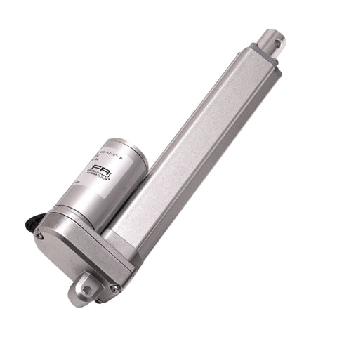
Rod-style linear actuators represent the most widely used actuator configuration in both industrial and consumer applications. Their popularity stems from their versatility, compact retracted length, and the wide range of specifications available. Understanding the internal mechanics of these actuators helps explain why they've become the industry standard for telescopic linear motion.
How Rod-Style Actuators Work
The basic rod-style actuator consists of four primary components working in sequence: a DC motor, a gearbox, a lead screw (or ball screw in high-performance models), and an extending rod. The motor converts electrical energy into rotational motion. This rotation passes through the gearbox, which reduces speed while proportionally increasing torque—a critical trade-off that allows actuators to generate substantial force from relatively small motors.
The gearbox output drives the lead screw, a threaded rod that remains fixed in position. As the lead screw rotates, a nut assembly travels along its length. This nut is connected to the extending rod, converting rotational motion into linear travel. The distance the rod extends beyond the actuator body is called the stroke length, typically ranging from 2 inches (50mm) to 60 inches (1500mm) in standard models.
Motor Positioning Configurations
Rod-style actuators come in two primary motor configurations, each offering distinct advantages. Parallel motor configuration positions the motor alongside the extending rod, creating a wider but shorter profile. This design is common in standard duty actuators where space along the stroke axis is limited but width is less constrained.
Perpendicular motor configuration, found in many premium models, mounts the motor at a right angle to the rod using an additional gear set. This creates a more compact overall width but increases the body length slightly. The perpendicular design often allows for better heat dissipation and easier servicing, making it popular in industrial actuators that run frequent duty cycles.
Applications and Performance Range
Rod-style actuators are specified across an enormous range of applications precisely because they're available in such diverse specifications. Force ratings typically span from 10 lbs (45N) in micro linear actuators to over 2,200 lbs (10,000N) in heavy-duty industrial models. Speed capabilities range from 0.1 inches per second for high-force applications to over 3 inches per second in lighter-duty, faster models.
Common applications include automated window openers, adjustable furniture, hatch and door mechanisms, solar panel tracking systems, and industrial positioning equipment. The telescopic nature of rod-style actuators makes them ideal for applications requiring significant stroke length while maintaining compact dimensions when retracted. Many models now include feedback sensors that provide real-time position data, enabling precise control and synchronization in multi-actuator systems.
Bullet Series Linear Actuators: Streamlined In-Line Design
Bullet series actuators represent a specialized evolution of the rod-style design, engineered specifically for applications where aesthetics and space constraints along axes perpendicular to the stroke are critical. By repositioning the motor and gearbox in-line with the extending rod rather than parallel or perpendicular to it, these actuators achieve a dramatically reduced diameter.
Design Philosophy and Benefits
The inline configuration of bullet actuators creates a cylindrical profile that's significantly narrower than standard rod-style actuators of equivalent force rating. While this design increases the overall extended length compared to perpendicular-motor actuators, it provides critical advantages in applications with limited radial clearance. The streamlined appearance also makes them aesthetically superior for visible installations in furniture, exhibits, or architectural elements.
This form factor excels in tubular frames, narrow cavities, and applications where the actuator passes through a sleeve or mounting tube. The reduced diameter also minimizes visual impact in consumer-facing applications like adjustable monitor arms, retail displays, and modern furniture where mechanical components should be as unobtrusive as possible.
Typical Specifications and Use Cases
Bullet series actuators typically offer force ratings from 50 lbs (220N) to 400 lbs (1,800N), making them suitable for light to medium-duty applications. Stroke lengths generally range from 2 inches (50mm) to 20 inches (500mm). While their force capacity is more limited than heavy-duty industrial rod actuators, their unique form factor makes them irreplaceable in space-constrained applications where standard actuators simply won't fit.
Popular applications include medical equipment adjustments, ergonomic office furniture, aerospace interior components, automotive seating mechanisms, and custom home automation projects where concealment is important. The bullet design is particularly valuable in marine applications where minimizing profiles reduces wind resistance and improves aesthetics.
Track Linear Actuators: Fixed-Length Sliding Solutions
Track linear actuators fundamentally differ from rod-style designs in one critical aspect: instead of a rod that extends telescopically, they use a sliding carriage that travels along an exposed lead screw track. This design choice creates a fundamentally different set of characteristics, advantages, and limitations that make track actuators ideal for specific application types while unsuitable for others.
How Track Actuators Function
Like rod-style actuators, track actuators use a motor, gearbox, and lead screw to generate linear motion. However, the lead screw remains exposed along the entire stroke length, with a carriage assembly riding directly on it. As the motor drives the lead screw rotation, the carriage translates along the track. This means the actuator maintains a constant physical length regardless of position—the stroke length equals the lead screw length.
The carriage typically includes multiple bearing or guide elements that run along parallel guide rails, ensuring smooth motion and preventing rotation. This guidance system allows track actuators to handle moment loads (side forces) more effectively than rod-style actuators, which can bind or wear prematurely under similar conditions.
Design Advantages and Limitations
The fixed-length design of track actuators offers significant advantages in design predictability. There's no change in the actuator's spatial envelope during operation, simplifying mechanical design and eliminating concerns about clearance for extended rods. The exposed guidance system also handles lateral forces and moments better than rod actuators, making them more suitable for applications where loads aren't perfectly aligned with the stroke axis.
However, the exposed lead screw presents vulnerability to contamination. Dust, debris, moisture, or other contaminants can accumulate on the screw threads, potentially causing premature wear or binding. This makes track actuators less suitable for dusty industrial environments or outdoor applications unless additional protective measures are implemented. Most track actuators also have lower IP ratings than sealed rod-style designs.
Ideal Applications for Track Actuators
Track actuators excel in sliding applications where the motion path is horizontal or at a shallow angle and the actuator can be mounted in a protected environment. Custom cabinetry represents one of their most popular uses, particularly for sliding cabinet doors, pop-up shelves, and concealed compartments. The fixed length makes them easy to integrate into cabinet designs without requiring space for actuator extension.
Other common applications include sliding doors and windows, adjustable partitions, retail display positioning, and entertainment systems where flat-panel displays or components slide into position. Combined with slide rails or drawer slides, track actuators create smooth, controlled motion for panels and components up to several hundred pounds.
Lifting Columns: Vertical Load Specialists
Lifting columns represent the most specialized category of electric linear actuators, engineered specifically for vertical orientation and high load capacity. Their unique multi-stage telescoping design and structural optimization for axial loads make them the preferred choice for applications like height-adjustable desks, TV lifts, and industrial positioning systems that operate primarily in the vertical axis.
Multi-Stage Telescoping Design
Unlike rod-style actuators that extend a single rod, lifting columns consist of multiple nested tubular stages that extend sequentially. A typical two-stage column has an outer tube, an intermediate tube, and an inner tube, with each stage extending approximately half the total stroke length. This design allows the column to collapse into a much shorter profile than a single-stage actuator with equivalent stroke—critical for applications like desks that need to lower to minimum height.
The internal mechanism still uses a motor, gearbox, and lead screw, but the screw drives a complex linkage system that controls the sequential extension of each stage. High-quality lifting columns use precision guidance systems within each stage to maintain alignment and prevent wobble under load. The tubular construction provides excellent rigidity in compression, allowing columns to support substantial loads even at full extension.
Load Capacity and Structural Advantages
Lifting columns are designed to carry loads from approximately 150 lbs (680N) to over 1,500 lbs (6,700N) per column, with systems typically using two to four synchronized columns for large surfaces. The tubular design provides inherently high buckling resistance compared to rod actuators of similar weight, allowing them to support greater loads while extended vertically.
Most column lifts include integral mounting plates at both ends, eliminating the need for separate mounting brackets and simplifying installation. The base typically includes adjustment feet for leveling, while the top plate provides bolt patterns for attaching desktops, equipment platforms, or other loads. This integrated mounting approach contributes to the column's structural integrity and reduces potential failure points.
Applications and Limitations
The vertical orientation requirement is both the lifting column's greatest strength and its primary limitation. These actuators are engineered with the assumption that loads are applied axially downward, with the column in compression. Using them horizontally or at significant angles compromises their load capacity and can lead to premature failure. For horizontal applications, rod-style or track actuators are more appropriate.
Within their design envelope, lifting columns excel. Height-adjustable standing desks represent their most common application, with synchronized columns providing stable, level lifting of work surfaces up to 200 lbs or more. TV lifts use single or dual columns to raise flat panels from cabinets or lower them from ceilings. Industrial workstations, medical equipment, and specialized material handling systems also frequently employ lifting columns where vertical positioning is required.
Creative DIY applications continue to emerge. Pop-up wine cellars that rise from basement floors, hidden projector lifts that descend from ceilings, and motorized standing platforms all leverage lifting columns' vertical load capacity and compact retracted profile. When paired with appropriate control boxes and power supplies, these columns enable sophisticated automation in residential and commercial settings.
Key Specifications and Configuration Options
Regardless of which actuator type suits your application's form factor requirements, understanding the key specifications that differentiate individual models is essential for proper selection. These specifications determine whether an actuator can physically perform the required task and how well it will perform over its operational lifetime.
Force and Speed: The Fundamental Trade-Off
Force rating, typically specified in pounds (lbs) or Newtons (N), indicates the maximum load the actuator can push or pull. This specification is load-dependent—actuators generally have different push and pull capacities, with push force usually slightly higher. When selecting force rating, always include a safety factor to account for friction, misalignment, and dynamic loads. A 30-50% safety margin is typical for most applications.
Speed, measured in inches per second (in/s) or millimeters per second (mm/s), inversely relates to force capability. Given a fixed motor power, the gearbox ratio determines whether that power delivers high speed with low force or high force with low speed. A 12V actuator might offer 2 inches per second at 100 lbs force, or 0.5 inches per second at 400 lbs force—but not both simultaneously. Understanding your application's priority helps select the appropriate balance.
Stroke Length and Physical Dimensions
Stroke length defines how far the actuator can extend. For rod-style and bullet actuators, stroke length directly impacts retracted length—longer strokes require longer actuator bodies. A 12-inch stroke actuator might have a 16-inch retracted length, while a 6-inch stroke model might retract to 10 inches. This relationship is critical in space-constrained applications.
Track actuators maintain constant length equal to their stroke plus mounting ends, while lifting columns offer the best stroke-to-retracted-length ratio due to their multi-stage design. A two-stage column with 20-inch stroke might retract to just 30 inches, whereas a rod actuator would need roughly 32-36 inches when retracted.
Voltage Options and Power Supply Considerations
Electric linear actuators commonly operate at 12V or 24V DC, with some models available in 36V or 48V configurations for higher-power applications. Voltage selection should align with your available power infrastructure. Automotive and solar applications typically use 12V, while industrial systems often standardize on 24V for better efficiency over longer cable runs.
Current draw varies significantly with load—an actuator might draw 2A under no load but spike to 8-10A when pushing maximum force. Selecting appropriate power supplies requires understanding not just steady-state requirements but also startup inrush current. Undersized power supplies cause voltage sag, reducing actuator speed and potentially triggering thermal protection.
Position Feedback Options
Feedback actuators include sensors that report the actuator's position in real-time. The two primary feedback types are potentiometric and Hall-effect sensors. Potentiometric feedback uses a resistive element that changes resistance proportionally with position, providing an analog voltage output typically from 0-5V or 0-10V representing 0-100% extension.
Hall-effect feedback counts magnetic pulses as the actuator moves, providing more precise position information and the ability to detect speed and direction. This digital feedback integrates easily with microcontrollers like Arduino and enables closed-loop control for precise positioning, synchronization of multiple actuators, and detection of obstructions or jams.
IP Ratings and Environmental Protection
Ingress Protection (IP) ratings indicate how well the actuator's enclosure protects internal components from contaminants. The rating uses two digits: the first indicates solid particle protection (0-6), the second indicates liquid protection (0-8). An IP54 rating means protection against dust accumulation (5) and water splashing from any direction (4).
Indoor applications in clean environments may only require IP42 protection, while outdoor installations need minimum IP65 (dust-tight and protected against water jets). Marine environments demand IP66 or IP67 ratings. Higher IP ratings typically mean higher cost and slightly reduced efficiency due to additional sealing, so select the minimum rating that meets your environmental requirements.
Selecting the Right Actuator Type for Your Application
Choosing the appropriate actuator type requires analyzing your application across several dimensions simultaneously. The decision framework should consider spatial constraints, load characteristics, environmental conditions, and control requirements in that priority order, as each factor progressively narrows the field of suitable options.
Start by defining your spatial envelope. If your application is vertical with the actuator in compression, lifting columns offer the best load capacity and retracted-to-stroke ratio. If you need telescopic motion in a horizontal or angular application with limited width, bullet actuators may be ideal. For sliding applications where the actuator can remain a fixed length, track actuators provide robust performance. Rod-style actuators serve as the versatile default for general applications or when other specialized types don't fit.
Next, calculate your load requirements including safety factors. Map these against available specifications in your preferred actuator type. If your required force exceeds what's available in a particular form factor, you'll need to either select a different actuator type or redesign your mechanical advantage using levers, linkages, or mounting geometry to reduce the required force.
Consider environmental exposure and required duty cycle. Outdoor or harsh-environment applications demand higher IP ratings, which may eliminate some actuator types or models. Continuous or high-duty-cycle applications need actuators with better thermal management and potentially higher-quality internal components than intermittent-use applications. Industrial-grade actuators typically specify duty cycle ratings that should match or exceed your requirements.
Finally, evaluate control requirements. If you need precise positioning, load monitoring, or synchronized multi-actuator motion, feedback becomes essential. If your application requires integration with existing control systems, verify compatibility between the actuator's voltage, feedback type, and your controller's capabilities.
Conclusion: Matching Actuator Type to Application
Understanding the four primary types of electric linear actuators—rod-style, bullet series, track, and lifting column—empowers you to make informed decisions that optimize performance, reliability, and cost. Each type evolved to solve specific challenges: rod-style actuators provide versatile telescopic motion, bullet actuators minimize radial profile, track actuators handle sliding applications with fixed envelopes, and lifting columns maximize vertical load capacity.
The wide range of specifications available within each type means that most applications can be satisfied by multiple actuator designs, making the selection process as much about understanding trade-offs as finding minimum requirements. A thorough analysis of spatial constraints, load characteristics, environmental conditions, and control needs will guide you to the optimal solution.
At FIRGELLI Automations, our two decades of engineering experience in electric actuation systems means we've seen virtually every application challenge. Whether you're designing industrial automation equipment or building a custom DIY project, selecting the right actuator type and specifications establishes the foundation for successful implementation.
Frequently Asked Questions
What is the main difference between rod-style and track actuators?
The fundamental difference lies in how they extend. Rod-style actuators use a telescoping rod that extends from the actuator body, changing the overall length from retracted to extended position. Track actuators maintain constant physical length, with a carriage sliding along an exposed lead screw. This makes rod-style actuators better for applications needing compact retracted length, while track actuators excel in sliding applications where constant actuator length simplifies design and the actuator can be mounted in a protected environment.
Can lifting columns be used horizontally?
No, lifting columns are specifically engineered for vertical orientation with loads in compression. Using them horizontally dramatically reduces their load capacity and can cause premature failure of the internal guidance system. The multi-stage telescoping design that provides excellent vertical rigidity offers minimal resistance to bending moments in horizontal orientation. For horizontal applications requiring similar stroke-to-length ratios, consider rod-style actuators with appropriate mounting brackets to support side loads.
Do I need an actuator with feedback?
Feedback is necessary when you need precise position control, want to synchronize multiple actuators, or need to monitor actuator status during operation. Applications like synchronized multi-column standing desks, precision positioning systems, or automation sequences where actuator position affects subsequent operations all benefit from feedback. Simple on-off applications like opening a hatch to a fixed position using limit switches don't require feedback, saving cost and complexity. Potentiometric feedback provides adequate position information for most applications, while Hall-effect feedback offers higher precision for demanding positioning tasks.
How do I determine what force rating I need?
Calculate the maximum load your actuator must move, accounting for the weight of all components, friction in the mechanism, and any external forces like wind or pressure. Apply mounting geometry to determine the actual force at the actuator—loads applied perpendicular to the stroke or at a distance from the mounting point require significantly more actuator force. Add a 30-50% safety factor to account for dynamic loads, friction variations, and manufacturing tolerances. If your calculated requirement exceeds available actuator specifications, consider redesigning your mechanism to improve mechanical advantage or using multiple actuators to distribute the load.
What's the difference between 12V and 24V actuators?
The voltage difference primarily affects current requirements and wire sizing rather than performance. A 24V actuator draws approximately half the current of an equivalent 12V model at the same power level, allowing use of smaller gauge wire over longer distances with less voltage drop. This makes 24V preferable for industrial installations or applications with long cable runs. 12V actuators integrate more easily with automotive, marine, and solar applications where 12V power is standard. Some high-force actuators are only available in 24V because the required power would demand impractically high current at 12V. Performance specifications like speed and force are determined by the motor and gearbox design, not voltage—equivalent models at different voltages perform identically.
What IP rating do I need for outdoor use?
Outdoor applications exposed to rain should use minimum IP65-rated actuators, which are dust-tight and protected against water jets from any direction. If the actuator will be submerged or exposed to high-pressure washing, IP66 or IP67 ratings provide additional protection. Sheltered outdoor locations might function adequately with IP54 or IP55 ratings if protected from direct rain. Marine environments require IP66 minimum due to salt spray and potential wave action. Remember that higher IP ratings add cost and may slightly reduce efficiency due to additional sealing, so select the minimum rating that meets your environmental exposure without over-specifying.


