Stroke Selector
Linear Actuator Stroke Selector
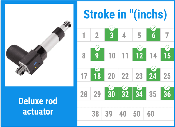
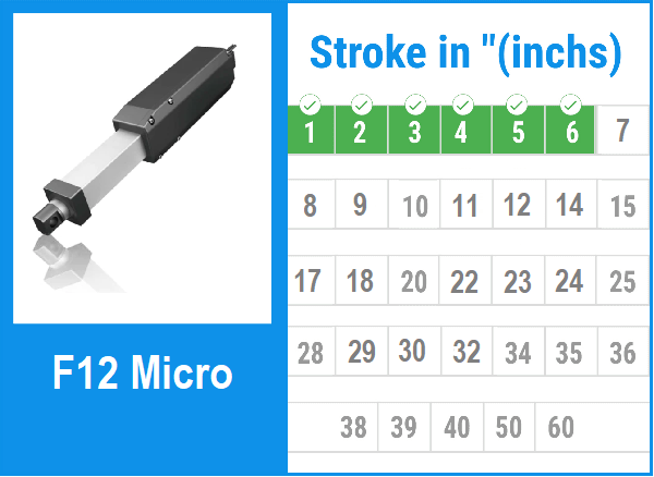
Use this page to compare the available stroke options for FIRGELLI linear actuator families. The green marks in each product image show the stroke lengths offered for that actuator line. Select a product image to view the matching product page, then confirm force, speed, mounting dimensions, duty cycle, and control requirements before ordering.
Stroke length is the distance the actuator rod or carriage travels from fully retracted to fully extended. It is not the same as overall actuator length, and it is not always the same as the motion you get at the load. In a simple straight push application, a 10 inch stroke can create close to 10 inches of travel. In a hinged lid, trap door, hatch, TV lift, solar panel tilt, or linkage, the same 10 inch actuator stroke may create a much larger or smaller movement at the moving part depending on bracket position and geometry.
If you already know the movement you need, start by finding actuator families below that offer that stroke. If you are still working out geometry, use the linear motion calculator or read how to calculate the exact linear actuator stroke length before choosing a product family.
What's Covered in the Guide
How to Use This Stroke Selector
First, define the movement at the mechanism, not just the actuator. Measure the required open and closed positions, then decide where the fixed and moving brackets can be mounted. The actuator must fit when fully retracted, must not bottom out mechanically before its internal limit switch stops the motor, and must have enough extended length to reach the final position without forcing the linkage past its intended travel.
Second, treat the listed stroke as a selection filter, not the whole design. Two actuators can share the same stroke but differ in force rating, speed, feedback, protection, noise, mounting style, and body length. For force and general sizing method, review the linear actuator sizing guide and the force and stroke guide.
Third, leave room for adjustment. In most fabricated projects, bracket holes, hinge position, material flex, and load distribution vary slightly from the CAD model or bench measurement. A practical approach is to choose a stroke that reaches the required motion while leaving a small installation margin at each end. Do not use the actuator as a hard mechanical stop; use the actuator limits, external stops, or properly designed brackets so the system does not jam.
Actuator Stroke Option Images
The images below are intended as a quick visual selector. Green highlights indicate the stroke options available for each actuator family. Open the product page for the actuator line you are considering and verify the current product specifications before final design work.





Engineering Checks Before Selecting Stroke
Use the stroke selector together with a short checklist. This reduces the chance of choosing an actuator that has the right travel but the wrong installation envelope or mechanical advantage.
| Design question | Why it matters | Builder check |
|---|---|---|
| How much travel is required at the load? | The load movement may not equal actuator stroke when hinges or linkages are involved. | Measure closed and open positions, then mock up the bracket locations with cardboard, CAD, or temporary holes. |
| What is the retracted length limit? | A long-stroke actuator also has a longer body, which may not fit in the closed position. | Check the product drawing for retracted length and leave clearance for rod ends, clevises, wiring, and bracket rotation. |
| Will the actuator be pushing, pulling, or both? | Side loading and misalignment reduce life and can damage the rod, track, or mounting points. | Keep the actuator in line with the force path and use pivots so the actuator is not forced to bend. |
| Is position feedback required? | Stroke alone does not provide position control for synchronized or programmable systems. | Consider feedback actuator families when the controller needs to know actual position. |
| Does the application need adjustable endpoints? | Some mechanisms need fine tuning after installation to prevent overtravel. | Review adjustable limit switch actuators when endpoint tuning is important. |
Practical Stroke Selection Examples
Example 1: Straight sliding drawer or tray. Assume a drawer must move 14 inches from closed to open and the actuator is mounted parallel to the slide. A 14 inch stroke is the theoretical match. In practice, confirm the drawer does not hit a hard stop before the actuator reaches its internal limit. If the drawer only needs 13.5 inches of usable opening, a 14 inch stroke may still work if the brackets are positioned so the actuator is not stalled at either end.
Example 2: Hinged hatch. Assume a hatch rotates from closed to 70 degrees open. The actuator does not need to move 70 inches or match the arc length of the hatch edge. It only needs to change length by the distance between the two actuator mounting points from closed to open. That difference may be much shorter than the hatch edge travel. For this type of geometry, use a sketch or the hinged actuator stroke calculator to test bracket locations before selecting from the green stroke options.
Example 3: Adjustable vent or panel. A short stroke can create a large angular change when the actuator is mounted close to the hinge, but force demand rises because the actuator has less leverage. Moving the bracket farther from the hinge can reduce force requirement but may require a longer stroke. This is the common tradeoff: shorter stroke often means compact packaging, while longer stroke can provide smoother geometry and better mechanical advantage.
Example 4: Two actuators lifting one structure. When two actuators share a load, stroke matching is not the only concern. The system may need feedback, matched loading, careful wiring, or a controller that keeps both sides synchronized. If one side reaches the end before the other, the frame can rack or bind. Select the stroke only after deciding how the two actuators will be controlled and how the structure will tolerate small differences in travel.
Common Stroke Selection Mistakes to Avoid
- Choosing stroke from the desired visible motion only. Always calculate the actuator length change between the two mounting points.
- Ignoring retracted length. A longer stroke actuator may not fit into the available space when closed.
- Using the actuator as a structural stop. Design the mechanism so the actuator is not forced into compression, bending, or stall at the end of travel.
- Forgetting the bracket sweep. Clevis brackets rotate as the actuator changes angle. Leave enough clearance around the motor, rod, and wiring.
- Assuming stroke can always be shortened later. Some applications can use external stops or adjustable limits, but modification is not a substitute for correct sizing. Read about whether you can adjust linear actuator stroke length before relying on field changes.
- Selecting stroke before force. A geometry that works on travel can still fail if the actuator does not have enough force at the worst angle. Check the load case with the linear motion calculator.
Stroke Selector FAQ
What stroke length should I choose if my required travel falls between two options?
Choose based on the full mechanism, not only the number. If the next longer stroke can be mounted so it does not overtravel the load, it may provide useful adjustment room. If the longer actuator body will not fit or would force the mechanism past a safe position, choose a shorter stroke and revise the linkage. Never assume extra stroke is harmless.
Is actuator stroke the same as extended length?
No. Stroke is only the travel distance. Extended length is the retracted length plus the stroke, measured between the mounting points defined by the product drawing. Always check both dimensions.
Can I stop an actuator halfway through its stroke?
Yes, with suitable wiring and control you can remove power before the actuator reaches its internal limit. However, if the application must repeatedly stop at accurate positions, consider feedback options and a controller designed for position control.
When should I consider an adjustable limit switch actuator?
Use an adjustable limit option when the final endpoints need tuning after installation, such as cabinet lifts, access panels, prototypes, or mechanisms where bracket locations may vary slightly. Adjustable limits help fine tune travel, but the actuator still needs adequate force, correct alignment, and enough physical clearance.
Does a longer stroke reduce actuator force?
Stroke length by itself does not define force. Force depends on the actuator model, motor, gearing, screw, and application geometry. A longer stroke may change your bracket geometry, which can change the force required at different points in travel.
How much safety margin should I leave?
For fit, leave enough clearance so the actuator is not mechanically trapped at either end. For force, use a margin appropriate to the application, load uncertainty, friction, and duty cycle. If exact values are unknown, build a prototype or test fixture using conservative assumptions before committing to production brackets.