Selecting the right electric linear actuator for your project requires careful consideration of multiple technical parameters. While the concept seems straightforward—converting electrical energy into precise linear motion—the reality is that improper actuator selection can lead to project failure, wasted resources, and potential safety hazards. Whether you're designing an automated hatch system, building a custom TV lift, or engineering an industrial automation solution, understanding the fundamental selection criteria will save you time and money while ensuring optimal performance.
🎥 Video — Four Steps to Choosing the right Linear Actuator
At FIRGELLI Automations, we've helped thousands of engineers, DIY enthusiasts, and industrial designers navigate the actuator selection process. From micro linear actuators generating 15 lbs of force to industrial actuators capable of moving 2,200 lbs, the range of options can be overwhelming. This comprehensive guide breaks down the selection process into four essential steps, providing you with the technical knowledge and practical insights needed to make the right choice for your specific application.

Understanding Electric Linear Actuators
Before diving into the selection process, it's important to understand what an electric linear actuator is and how it functions. In technical terms, a linear actuator is an electromechanical device that converts the rotational motion of an electric motor into controlled linear motion. This is typically achieved through a lead screw or ball screw mechanism housed within the actuator body.
The motion produced by linear actuators is commonly achieved in two configurations: rod-style actuators feature an extending and retracting shaft, while track-style actuators use a sliding block that moves along a fixed rail. Both designs serve different purposes depending on space constraints, mounting requirements, and application specifics.
Linear actuators have become ubiquitous in modern life, with applications spanning healthcare equipment, automotive systems, home automation, solar tracking arrays, aerospace technology, and industrial machinery. Most people interact with linear actuators daily—in adjustable office chairs, car trunk lifts, hospital beds, or automated door systems—often without realizing the sophisticated engineering behind these devices.

Step 1: Determine Force Requirements
The first and most critical parameter in actuator selection is force capacity. This specification, typically measured in pounds (lbs) or Newtons (N), represents the maximum load the actuator can push or pull. However, determining the actual force requirement is more complex than simply weighing the object you intend to move.
Calculating Static Load
For straightforward applications—such as pushing a door open, extending a platform, or lifting a load vertically—the force calculation is relatively simple. You need an actuator with a force rating that exceeds the weight of the object, with an appropriate safety factor. A general rule of thumb is to select an actuator with a force capacity 20-30% higher than the calculated load to account for friction, misalignment, and aging components.
Understanding Leverage and Mechanical Advantage
The complexity increases significantly when dealing with pivoting applications, such as hatches, lids, or articulating arms. In these scenarios, the principles of leverage dramatically affect force requirements. Consider a 50-lb hatch: if the actuator mounting point is positioned close to the hinge (pivot point), the mechanical disadvantage can multiply the force requirement by a factor of five or even ten.

This phenomenon occurs because force requirements in pivoting systems follow the equation: Force × Distance from Pivot (actuator) = Load × Distance from Pivot (load). When you mount an actuator close to the hinge for aesthetic or space reasons, you create a mechanical disadvantage that exponentially increases force demands. That 50-lb hatch can easily require 500 lbs of actuator force depending on mounting geometry.
Using Force Calculators
To accurately determine force requirements for complex applications, particularly those involving leverage, angular motion, or non-linear paths, use specialized calculation tools. Our linear actuator force calculator takes into account mounting positions, pivot points, angles of operation, and load weights to provide accurate force specifications. This eliminates guesswork and prevents costly mistakes in actuator selection.
Force Capacity Ranges
FIRGELLI Automations offers actuators across a comprehensive force spectrum. Micro actuators start at 15 lbs for precision applications like camera gimbals or small enclosures. Standard rod actuators typically range from 50 lbs to 500 lbs, suitable for most home automation and light industrial applications. Heavy-duty industrial actuators extend up to 2,200 lbs, engineered for demanding applications such as agricultural equipment, industrial machinery, or automotive systems requiring substantial force capacity.
Step 2: Determine Stroke Length Requirements
Stroke length refers to the total distance the actuator shaft extends from its fully retracted position to its fully extended position. This is a fundamental specification that must match your application's range of motion requirements.
Measuring Required Stroke
To determine the necessary stroke length, measure the total linear distance your application needs to travel. For a cabinet door that needs to open 12 inches, for example, you might assume a 12-inch stroke is sufficient. However, the actual requirement depends on mounting geometry. If the actuator is mounted at an angle or in a configuration where the effective linear extension differs from the actual travel distance, you may need a longer or shorter stroke.
For pivoting applications, the relationship between stroke and angular travel becomes more complex. A hatch that pivots 90 degrees might require anywhere from 8 to 24 inches of stroke depending on where the actuator attaches relative to the hinge. In these cases, physical mockups or CAD modeling help determine the precise stroke requirement across the entire range of motion.
Available Stroke Options
FIRGELLI Automations manufactures actuators with strokes ranging from 1 inch to 60 inches, providing solutions for virtually any application. Short-stroke actuators (1-4 inches) are ideal for valve control, locking mechanisms, or fine positioning adjustments. Medium-stroke actuators (6-18 inches) suit most furniture automation, hatch systems, and access panels. Long-stroke actuators (24-60 inches) are essential for TV lifts, standing desks, solar tracking systems, or applications requiring extensive travel.

Retracted Length Considerations
Don't overlook the actuator's retracted length when planning your installation. Rod-style actuators have a retracted length typically 1.5 to 2 times the stroke length. For space-constrained applications, this can be problematic. In these situations, track actuators offer an advantage because they maintain a constant overall length whether extended or retracted, with only the slider block moving along the rail. Alternatively, a column lift provides an excellent solution when you need a long stroke with minimal retracted height, using a telescoping design similar to a car antenna.
Step 3: Determine Speed Requirements
Actuator speed, measured in inches per second (in/s) or millimeters per second (mm/s), defines how quickly the actuator extends and retracts. This parameter directly impacts user experience and application functionality, but it comes with important trade-offs.
The Force-Speed Relationship
A fundamental principle of electric linear actuators is the inverse relationship between force and speed. This relationship is governed by the motor's power output and the gear ratio within the actuator. Higher force capacity typically requires higher gear reduction, which decreases speed. Conversely, faster actuators achieve their speed through lower gear ratios, sacrificing force capacity.
For example, an actuator rated at 500 lbs might operate at 0.5 inches per second, while a 100-lb actuator of similar design could achieve 2 inches per second. This trade-off is unavoidable with fixed-power motors, so selecting the right balance between force and speed is crucial for your application.
Typical Speed Ranges
Most standard linear actuators operate between 0.5 and 2.0 inches per second. Slow-speed, high-force actuators (0.1-0.5 in/s) are used in applications requiring substantial pushing power, such as lifting heavy hatches or positioning industrial equipment. Medium-speed actuators (0.5-1.5 in/s) suit most home automation, furniture mechanisms, and general-purpose applications. High-speed, lower-force actuators (1.5-3.0 in/s) are ideal for applications where rapid movement matters more than force capacity, such as camera rigs, display mechanisms, or access panels.
Manipulating Speed Through Design
While you cannot change an actuator's inherent speed rating, you can manipulate the effective speed of your application through clever mechanical design. For pivoting applications like hatches or doors, mounting the actuator closer to the pivot point increases the angular speed of the lid, even though the actuator itself extends at the same linear rate. This leverages the same mechanical principles discussed in force calculations—distance from the pivot affects both force requirements and effective speed.
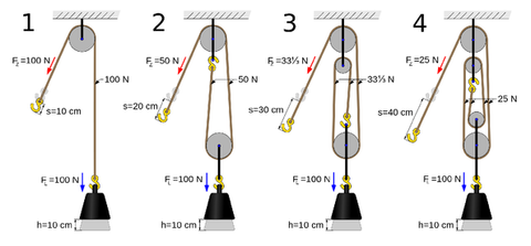
Pulley systems offer another method to modify effective speed and force. Using pulleys with specific ratios, you can increase lifting force while reducing speed, or vice versa. This mechanical advantage allows a single actuator model to be adapted to various force and speed requirements through external mechanisms rather than requiring different actuator specifications.
Synchronization Considerations for Multiple Actuators
When applications require two or more actuators working in tandem—such as lifting a large hatch or raising a platform—speed synchronization becomes critical. Actuators running at different speeds will cause binding, uneven loading, or structural stress. Feedback actuators with built-in position sensors and appropriate control systems ensure synchronized movement, preventing damage and ensuring smooth operation. For applications requiring precise coordination, investing in feedback-equipped actuators and proper control electronics is essential.
Step 4: Select the Appropriate Actuator Type
With force, stroke, and speed requirements defined, the final step involves selecting the actuator type that best suits your application's physical constraints, mounting requirements, and operational environment.
Rod-Style Actuators
Rod-style actuators are the most common and versatile design, featuring a telescoping shaft that extends and retracts from a cylindrical body. These actuators excel in applications requiring straightforward linear motion with flexible mounting options. The rod can push or pull, and mounting brackets on both ends allow for various installation configurations.
Rod actuators are available in multiple form factors. Standard industrial housings provide durability and weather resistance. Bullet actuators offer a sleek, compact design ideal for applications where aesthetics matter. Premium models include features like limit switches, feedback sensors, and protective coatings for harsh environments.
The primary limitation of rod-style actuators is their changing overall length during operation. The total length when extended is approximately twice the stroke plus the body length, requiring adequate clearance space in your installation.
Track Actuators
Track actuators solve the space constraint issue by maintaining a constant overall length throughout their range of motion. These units consist of a fixed rail with a moving carriage block that slides along the track. The entire mechanism stays the same length whether the carriage is at one end or the other.
This design is ideal for tight spaces where a traditional rod actuator's changing length would be problematic. Common applications include drawer slides, sliding panels, camera sliders, and any application where space constraints prevent the use of extending rods. Track actuators also provide excellent lateral stability since the carriage rides on a fixed rail rather than extending a cantilevered shaft.

Column Lifts
A column lift uses a telescoping design to achieve long strokes with minimal retracted height. Similar to a car antenna or telescoping pole, these actuators nest multiple tubes inside each other, extending upward when activated. This design is perfect for applications like TV lifts, pop-up displays, or vertical positioning systems where floor space is limited but substantial vertical travel is required.
Column lifts typically offer strokes from 20 to 40 inches or more while maintaining a retracted height of only 12-18 inches. They're designed primarily for vertical lifting applications and may not be suitable for horizontal pushing or pulling due to the telescoping design's lateral flexibility.
Specialized Actuator Types
Beyond the primary categories, specialized actuators serve niche applications. Micro linear actuators provide precision positioning in extremely compact packages for robotics, medical devices, or intricate mechanisms. Rotary actuators convert linear motion into rotational movement for valve control or positioning applications. High-capacity industrial actuators feature reinforced construction, sealed housings, and premium components for demanding environments.
Additional Selection Factors
Voltage and Power Requirements
Electric linear actuators typically operate on 12V or 24V DC power, with some models available in other voltages. The voltage selection affects current draw, wiring requirements, and compatibility with control systems. Higher voltage actuators (24V) generally draw less current for equivalent power output, reducing wire gauge requirements and voltage drop issues over long cable runs. Ensure you have an appropriate power supply that can deliver sufficient current for your actuator's peak load requirements, typically 2-8 amps depending on force rating and speed.
Environmental Considerations
Consider the operating environment when selecting an actuator. Indoor applications in clean, temperature-controlled spaces have minimal requirements. Outdoor installations, marine environments, or industrial settings require actuators with appropriate IP (Ingress Protection) ratings, corrosion-resistant finishes, and sealed housings to prevent contamination from dust, moisture, or chemicals. Temperature extremes also affect performance—extreme cold can increase friction and reduce battery capacity, while excessive heat may degrade seals and lubricants.
Duty Cycle and Longevity
Duty cycle refers to the percentage of time an actuator can operate before requiring a rest period to cool down. Most standard actuators have a 20% duty cycle, meaning they can run for 2 minutes out of every 10. Intermittent use applications like hatches, doors, or furniture easily meet this requirement. Continuous or high-frequency applications require industrial-grade actuators designed for extended duty cycles or continuous operation.
Control Systems and Integration
After selecting the appropriate actuator, you need a method to control it. Options range from simple rocker switches for basic on/off control to sophisticated systems with programmable logic, position feedback, and wireless operation. A control box provides convenient push-button or remote control operation for home automation applications. For custom projects, Arduino and other microcontroller platforms offer programmable control with integration capabilities for sensors, limit switches, and automated sequences.
Practical Application Examples
Automated RV Storage Hatch
An RV storage hatch weighing 35 lbs with dimensions of 24" × 36" needs automation. The hatch pivots on hinges at one edge. Mounting the actuator 6 inches from the hinge to achieve 90-degree opening creates a mechanical disadvantage factor of approximately 4:1 based on geometric calculations. This increases the force requirement to roughly 140 lbs. Selecting a 200-lb capacity actuator provides adequate safety margin. A 12-inch stroke sufficiently opens the hatch to 90 degrees. Speed is not critical, so a standard 0.75 in/s actuator works well. A rod-style actuator with weather-resistant housing and mounting brackets completes the specification.
Pop-Up TV Cabinet
A custom TV lift mechanism for a 45-inch television in a cabinet requires vertical travel of 30 inches to raise the TV from concealment to viewing height. The TV and mounting plate weigh 65 lbs total. Since this is a vertical lift with minimal mechanical disadvantage, an actuator rated for 100 lbs provides sufficient capacity with safety margin. A column lift with 30-inch stroke fits the retracted height constraint of 15 inches. Moderate speed (1.0 in/s) provides smooth, appealing operation. Feedback actuators with position control ensure repeatable positioning at the desired viewing height, controlled via remote control for convenience.
Industrial Conveyor Gate
An industrial conveyor system needs automated gates that slide horizontally to control material flow. Each gate weighs 120 lbs and travels 18 inches. The horizontal sliding motion with linear bearings reduces friction significantly. A 150-lb force rating handles the load with consideration for startup friction. A track actuator with 18-inch stroke provides the necessary travel while maintaining constant overall length—important in the tight conveyor framework. The harsh industrial environment requires sealed, IP65-rated housing. High-frequency operation demands industrial-grade components with extended duty cycle ratings.
Summary
Choosing the right linear actuator requires methodical evaluation of four critical parameters: force requirements accounting for mechanical advantage, appropriate stroke length for the required travel distance, speed that balances performance with force capacity, and actuator type that fits the physical constraints of your application. By carefully calculating these specifications and considering additional factors like environmental conditions, control requirements, and duty cycle, you can confidently select an actuator that delivers reliable performance and long service life.
FIRGELLI Automations' comprehensive product line ensures you'll find an actuator that meets your specific needs, whether you're working on a home automation project, industrial application, or custom engineering solution. Proper selection at the outset prevents costly mistakes and ensures your project succeeds.
Frequently Asked Questions
How do I calculate the actual force required for a pivoting application?
For pivoting applications, the force requirement depends on the moment arms—the distances from the pivot point to both the load's center of mass and the actuator mounting point. Use the formula: (Load Weight × Load Distance from Pivot) / (Actuator Distance from Pivot) = Required Force. For example, if a 50-lb hatch has its center of mass 15 inches from the hinge, and you mount the actuator 3 inches from the hinge, the calculation is (50 × 15) / 3 = 250 lbs required force. Always add a 20-30% safety margin to account for friction, binding, and peak loads during acceleration. Our online force calculator simplifies this process by accounting for angle changes throughout the range of motion.
Can I use two actuators together for heavier loads?
Yes, multiple actuators can work together to lift heavier loads or provide balanced lifting for wide platforms and large hatches. However, synchronization is critical. Standard actuators without feedback may run at slightly different speeds due to manufacturing tolerances, load distribution, or voltage variations, causing binding and uneven stress. For reliable multi-actuator systems, use feedback actuators with position sensors paired with a control system that monitors and adjusts each actuator's position to maintain synchronization. This ensures smooth, balanced movement and prevents structural damage from misalignment.
What if I need more stroke than I have mounting space for?
Space constraints are common challenges in actuator installations. For applications requiring long stroke with limited mounting length, consider a column lift, which uses telescoping sections to achieve substantial travel with minimal retracted height—ideal for vertical applications. Alternatively, track actuators maintain constant length regardless of position, making them suitable for horizontal applications in confined spaces. For pivoting applications, repositioning the mounting points can reduce stroke requirements, though this affects force and speed characteristics. Cable and pulley systems can also redirect motion, allowing the actuator to be mounted remotely from the point of action.
How can I make my actuator move faster without buying a new one?
While you cannot change an actuator's inherent extension/retraction speed, you can increase the effective speed of your application through mechanical design. For rotating applications like hatches or doors, mount the actuator closer to the pivot point—this reduces the arc distance the actuator travels while the far edge of the door moves through a larger arc, increasing angular speed. However, this mounting change increases force requirements due to mechanical disadvantage. Alternatively, pulley systems with appropriate ratios can modify speed characteristics, trading force for speed or vice versa. For new projects requiring faster speeds, select actuators specifically rated for higher speeds, keeping in mind they typically have lower force capacities at the same power level.
What specifications should I look for in actuators for outdoor or harsh environments?
Outdoor and harsh environment installations require actuators with appropriate environmental protection. Look for IP (Ingress Protection) ratings—IP65 or higher provides dust-tight sealing and protection against water jets, suitable for most outdoor applications. Marine environments demand corrosion-resistant materials like stainless steel housings and shafts, or protective coatings on aluminum components. Temperature ratings should match your climate—standard actuators typically operate from -20°F to 150°F, while extreme-duty models extend these ranges. Consider sealed limit switches and connectors to prevent moisture intrusion. For industrial settings with chemical exposure, verify material compatibility with specific contaminants. Industrial actuators designed for demanding environments include enhanced sealing, robust construction, and appropriate certifications for safety-critical applications.


