Introduction to External Limit Switches for Linear Actuators
When integrating linear actuators into your automation project, precise stroke control is often critical. Whether you're building a TV lift, custom standing desk, or industrial positioning system, you may find that the actuator's full stroke length exceeds your application requirements. While premium actuators with programmable internal limit switches offer maximum flexibility, they come at a higher cost and require additional technical expertise to configure.
External limit switches provide an elegant, cost-effective solution to this common engineering challenge. These simple yet reliable devices allow you to define custom travel limits without modifying the actuator itself or investing in more expensive programmable models. By strategically placing external limit switches along the actuator's path of travel, you can restrict extension, retraction, or both movements to precisely match your application needs. This approach is particularly valuable for budget-conscious projects, retrofit installations, or applications where stroke requirements may change over time.
In this comprehensive guide, we'll examine how external limit switches function, explore the different types available, and provide detailed wiring instructions for integrating them with your linear actuator system. Whether you're working with micro linear actuators for compact applications or industrial actuators for heavy-duty installations, the principles remain consistent.
Understanding Built-In Linear Actuator Limit Switches
Before exploring external solutions, it's important to understand what "built-in limit switches" means in actuator specifications. When a linear actuator features built-in or non-adjustable limit switches, these internal mechanisms serve a critical protective function. As the actuator shaft reaches full extension or retraction, the limit switch not only halts movement but also cuts power to the motor completely.
This automatic shutoff is essential for actuator longevity. Without it, the motor would continue attempting to drive the mechanism beyond its mechanical limits, drawing current while stalled. This condition generates excessive heat and will quickly damage or destroy the motor windings, gear train, and internal components. Built-in limit switches prevent this scenario by interrupting the circuit the moment the actuator reaches its mechanical endpoint.
However, these factory-installed limit switches are fixed at the absolute limits of the stroke length. If your application requires stopping at an intermediate position—say you need only 8 inches of travel from a 12-inch stroke actuator—the built-in switches cannot accommodate this. This is where external limit switches become invaluable, allowing you to define custom stop positions anywhere along the actuator's travel range without compromising the protection provided by the internal switches.
What Are External Limit Switches and How Do They Work?
An external limit switch is an electromechanical device designed to make or break an electrical connection when physically actuated. At its core, it functions as a simple on-off switch activated by mechanical contact rather than manual operation. When the actuator or an object attached to it contacts the switch mechanism, internal contacts either close (completing a circuit) or open (interrupting a circuit), depending on the switch configuration.
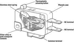
External limit switches come in numerous form factors to accommodate different motion control applications. Common actuation mechanisms include:
- Lever arms: The most common type, featuring a protruding arm that pivots when contacted, ideal for side-mounted installations
- Roller levers: Similar to standard levers but with a roller tip that reduces friction and wear from repeated contact
- Push buttons: Direct-contact switches that activate when pressed straight on, useful for end-of-travel limiting
- Spring-loaded plungers: Compact designs where a spring-loaded pin extends and retracts to trigger the switch
- Magnetic proximity switches: Touch-less operation using magnets attached to the moving component, eliminating mechanical wear entirely
The switches are manufactured with varying current and voltage ratings to match different actuator power requirements. Small micro actuators operating at 12V with low current draw can use compact, low-power switches, while larger industrial actuators running at 24V or higher with substantial amperage require more robust switch housings and contact materials capable of handling higher electrical loads without degradation.
Three Methods of Stroke Control with External Limit Switches
External limit switches can be configured in three distinct ways to control actuator travel, depending on your application requirements:
Limiting Extension Only
This configuration restricts how far the actuator can extend while allowing full retraction to the internal limit. It's commonly used when you need to prevent the actuator from extending too far and colliding with an obstacle or when a partial extension provides the optimal position. The external switch is positioned at your desired maximum extension point and wired to interrupt power during extension. Retraction remains unrestricted until the internal limit switch engages at full retraction.
Limiting Retraction Only
The inverse of extension limiting, this setup allows full extension while preventing complete retraction. This configuration is useful when you need to maintain a minimum extension length or when the fully retracted position would cause interference with other components. Applications might include maintaining clearance in tight installations or preventing mechanisms from closing completely. The external switch is mounted to interrupt power during retraction while extension proceeds normally to the internal limit.
Limiting Both Extension and Retraction
For maximum control, you can install two external limit switches—one for extension and one for retraction—creating a custom stroke length that's shorter than the actuator's full range. This is particularly valuable when you've specified an actuator with more stroke than needed or when integrating an actuator into a space-constrained installation. With both limits customized, the actuator operates within a precisely defined window of travel that matches your exact application requirements.
Required Components and Tools for Installation
To successfully integrate external limit switches with your actuator system, you'll need the following components and tools. FIRGELLI Automations offers a complete External Limit Switch Kit (EL-Kit) that includes most of these items in a ready-to-install package:
Essential Components
- External limit switch(es): One for single-direction limiting or two for both directions (included in FIRGELLI EL-Kit)
- Diode: Protects the circuit from voltage spikes and ensures proper directional control (pre-installed in FIRGELLI EL-Kit)
- Wire: Appropriate gauge for your actuator's current draw, typically 18-22 AWG for most applications
- Quick connectors or solder: For making secure electrical connections
- Fuses (optional but recommended): Inline fuses between the power supply and switch for circuit protection (included in FIRGELLI EL-Kit)
System Components You'll Need
- Electric linear actuator: Any linear actuator type—track actuators, bullet actuators, or feedback actuators
- Control source: Rocker switch, remote control, or control box
- Power source: DC power supply matching your actuator's voltage requirements (typically 12V or 24V)
Required Tools
- Wire stripper: For cleanly removing insulation without damaging conductors
- Crimping tool: If using crimp connectors (or soldering iron if soldering connections)
- Multimeter: Useful for verifying connections and testing switch operation
- Screwdriver set: For mounting the switch and securing terminal connections
- Drill and bits: If you need to create mounting holes for the limit switch
Step-by-Step Wiring Instructions
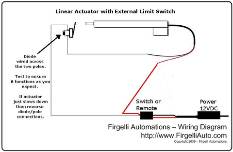
Wiring an external limit switch to your linear actuator is straightforward, but attention to detail ensures reliable operation. The key principle is that the external limit switch is wired in series with the ground (negative) cable between your control source and the actuator.
Basic Single Switch Wiring for Extension Limiting
Follow these steps to install a single external limit switch that limits extension:
- Disconnect power: Always begin with the power supply disconnected to prevent accidental activation or short circuits.
- Connect power and control: Wire your power supply to your control source (rocker switch, remote control, or control box) following the manufacturer's instructions.
- Identify ground wire: Locate the ground (negative) wire running from your control source to the actuator. This is typically black or marked with a minus symbol.
- Cut ground wire: Cut the ground wire at an appropriate point between the control source and actuator, leaving enough length on both sides for routing to the limit switch.
- Connect to limit switch: Connect one cut end of the ground wire to one terminal of the limit switch, and the other cut end to the remaining terminal. The diode (included in the FIRGELLI EL-Kit) should be pre-installed in the proper orientation.
- Mount the switch: Position the limit switch where the actuator or an object attached to it will contact the lever when you want motion to stop. Ensure the lever is oriented to be pressed during extension.
- Test operation: Reconnect power and test the system. The actuator should extend until it contacts the limit switch, then stop. Retraction should operate normally to full retraction.
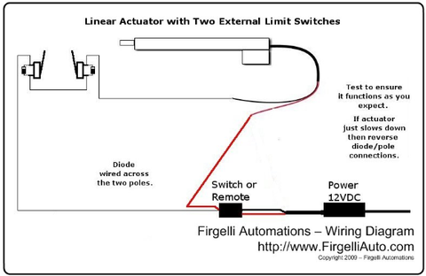
Dual Switch Wiring for Both Extension and Retraction Limiting
To limit both directions of travel, install a second external limit switch using the same method as the first, with one critical difference—the lever direction must be reversed. The second switch should be positioned where you want retraction to stop and oriented so the actuator contacts it when moving in the retraction direction.
Both switches are wired in series in the ground cable path. When the actuator extends and contacts the extension limit switch, that switch opens the circuit and stops extension. When retracting, the actuator eventually contacts the retraction limit switch, which opens the circuit and stops retraction. The orientation of the diode in each switch ensures the correct switch activates for each direction of travel.
Critical Wiring Considerations
Several important factors will ensure your installation functions reliably:
- Lever orientation is critical: The switch lever must be positioned to be pressed in the direction of travel you want to limit. Incorrect orientation will result in the switch not activating or activating in the wrong direction.
- Secure all connections: Loose connections can cause intermittent operation or complete failure. Use properly sized crimp connectors or quality solder joints.
- Wire gauge matters: Ensure wire gauge is appropriate for your actuator's current draw. Undersized wire creates resistance, voltage drop, and potential fire hazards.
- Diode orientation: The diode must be oriented correctly to allow current flow in the intended direction. The FIRGELLI EL-Kit includes pre-oriented diodes to eliminate this concern.
- Consider fuse protection: Adding inline fuses between the power supply and control switch provides an additional layer of protection against short circuits or actuator malfunctions.
Mounting and Positioning Strategies for Limit Switches
Proper physical mounting of external limit switches is as important as correct wiring. The switch must be positioned and secured to ensure consistent, reliable actuation at your desired position. Consider these mounting approaches:
Direct Contact Mounting
The simplest method involves mounting the limit switch so the actuator body or shaft directly contacts the switch lever. This works well when the actuator housing or a mounting bracket can be positioned to reliably strike the switch. Ensure the mounting surface is rigid—a flexible mount will absorb impact and may prevent reliable switch activation.
Flag or Cam Activation
For applications where the actuator body isn't ideally positioned to contact the switch, attach a "flag" or cam to the moving element. This can be a simple bracket, plate, or projection that extends from the actuator shaft or carriage and strikes the switch at the desired position. This method offers excellent flexibility in switch placement and is particularly useful with track actuators or systems using slide rails.
Adjustable Mounting for Fine-Tuning
For applications requiring precise positioning, mount the limit switch on a slotted bracket or sliding mechanism that allows fine adjustment after installation. This enables you to test the system and dial in the exact stop position without relocating the switch entirely. Use locking hardware to secure the final position once optimal placement is achieved.
Magnetic Proximity Method
For high-cycle applications or environments where mechanical wear is a concern, magnetic proximity switches eliminate physical contact entirely. A magnet is attached to the moving element, and a magnetic sensor detects when the magnet reaches the desired position. This approach offers essentially unlimited cycle life since no mechanical components wear, though it typically costs more than mechanical switches.
Troubleshooting Common Issues
Even with careful installation, you may encounter issues with external limit switch operation. Here are common problems and their solutions:
Actuator Doesn't Stop at Limit Switch
If the actuator continues moving past the limit switch position, check these potential causes:
- Verify the switch lever is properly oriented to be contacted by the moving element
- Ensure the switch is firmly mounted and not deflecting away from the contact point
- Check all electrical connections for looseness or corrosion
- Test the switch independently with a multimeter to verify it's functioning
- Confirm the diode is properly oriented in the circuit
Actuator Stops Before Reaching Limit Switch
If motion stops before the limit switch is contacted:
- Check for binding or excessive friction in the mechanical system
- Verify the actuator is receiving adequate voltage—measure at the actuator terminals under load
- Ensure the actuator's force rating is sufficient for the load being moved
- Check that the internal limit switches haven't been triggered prematurely
Intermittent Operation
If the limit switch works inconsistently:
- Inspect all wire connections for looseness—tug gently on each connection
- Check for wire damage, particularly where wires flex during actuator movement
- Verify the switch mounting is secure and hasn't loosened over time
- Ensure the contact point on the actuator or flag consistently strikes the same spot on the switch lever
- Consider if vibration or shock loads are affecting switch operation
Common Applications and Use Cases
External limit switches provide solutions across diverse automation applications. Understanding how others have implemented them can inspire your own projects:
Home Automation Projects
In residential applications, external limit switches enable custom positioning for TV lifts, allowing the television to stop at a comfortable viewing height rather than full extension. They're equally valuable in standing desk conversions where users want to set precise sitting and standing heights that differ from the actuator's full stroke range.
Industrial Positioning Systems
Manufacturing and industrial settings frequently use external limit switches with industrial actuators to control parts feeding, material handling, and assembly processes. The ability to easily adjust limit positions without reprogramming controllers makes them ideal for operations that handle multiple part sizes or configurations.
Automotive and Marine Applications
Vehicle and boat builders use external limit switches to control access panels, hatch covers, and convertible top mechanisms. The switches prevent over-travel that could damage bodywork or seals, while their simple wiring integrates easily with existing electrical systems.
Agricultural Equipment
Farm machinery and greenhouse automation systems rely on external limit switches to control ventilation panels, feeding mechanisms, and door systems. The rugged construction of industrial-grade limit switches withstands harsh agricultural environments where dust, moisture, and temperature extremes are common.
Advantages of External Limit Switches Over Programmable Alternatives
While feedback actuators with programmable controls offer sophisticated positioning capabilities, external limit switches provide several distinct advantages:
Cost effectiveness: External limit switches add minimal expense compared to upgrading to programmable actuators. For projects with tight budgets, this approach delivers position control at a fraction of the cost.
Simplicity: No programming knowledge, software, or complex controllers are required. The mechanical nature of limit switches makes them accessible to anyone comfortable with basic wiring, expanding their use to hobbyists and DIY enthusiasts who may lack experience with Arduino or other microcontroller platforms.
Reliability: Mechanical switches have proven reliability over decades of industrial use. Without complex electronics, there's less to fail, and troubleshooting is straightforward—the switch either makes contact or it doesn't.
Adjustability: Changing the stop position requires simply relocating the physical switch—no reprogramming or special tools needed. This makes external switches ideal for applications where positions may need adjustment during setup or over the product's lifetime.
Retrofit friendly: External switches integrate with any actuator that has basic directional control, making them perfect for upgrading or modifying existing systems without replacing actuators or controllers.
Selecting the Right Limit Switch for Your Application
Not all limit switches are created equal. Choosing the appropriate switch for your specific actuator and application ensures reliable, long-lasting performance:
Electrical Ratings
The switch must be rated to handle your actuator's voltage and current requirements. Check your actuator's specifications for operating voltage (typically 12V or 24V DC) and current draw under load. Select a switch rated at least 25% above these values to provide a safety margin. For high-current industrial actuators, ensure the switch contacts are rated for inductive loads, which generate voltage spikes during switching.
Mechanical Durability
Consider the expected cycle count for your application. Light-duty switches may be adequate for occasional-use applications like residential TV lifts, but high-cycle industrial applications require switches rated for millions of operations. Check the manufacturer's mechanical life specification and select accordingly.
Environmental Protection
The operating environment significantly impacts switch longevity. Indoor applications in climate-controlled spaces can use standard switches, but outdoor or harsh-environment installations require switches with appropriate IP (Ingress Protection) ratings. Look for IP65 or higher ratings for dust and water resistance in agricultural, marine, or outdoor applications.
Actuation Force and Overtravel
Different switches require different forces to activate, and they tolerate varying amounts of overtravel (how far the lever can be pushed past the activation point). Ensure your actuator can deliver sufficient force to reliably activate the switch, and that the switch can handle the overtravel that occurs between activation and the actuator fully stopping due to inertia.
Conclusion
External limit switches represent an elegant engineering solution to one of the most common challenges in linear actuator integration—customizing stroke length without the complexity and expense of programmable systems. By understanding the principles of limit switch operation, following proper wiring procedures, and implementing sound mounting strategies, you can achieve precise position control that perfectly matches your application requirements.
Whether you're working on a simple home automation project with a micro actuator or a complex industrial system with multiple industrial actuators, external limit switches provide reliable, adjustable control with minimal additional investment. The FIRGELLI External Limit Switch Kit simplifies the implementation further by including all necessary components with proper diode orientation and circuit protection already configured.
As with any electromechanical system, success comes from attention to detail during installation, proper component selection for your specific application, and thorough testing before putting the system into service. The result is a cost-effective positioning system that performs reliably for years with minimal maintenance.
Frequently Asked Questions
How many external limit switches can I use with one linear actuator?
You can use up to two external limit switches with a single linear actuator—one to limit extension and one to limit retraction. These are wired in series in the ground cable between your control source and the actuator. Additional switches beyond two would not provide useful functionality since you can only control two directions of travel (extend and retract). For applications requiring multiple intermediate stop positions, you would need to use programmable feedback actuators with position control instead.
Will using an external limit switch damage my actuator's internal limit switches?
No, external limit switches will not damage the internal limit switches. The external switch simply interrupts power before the actuator reaches its mechanical endpoint where the internal switches would activate. The internal limit switches remain functional and will still protect the actuator if the external switch fails or is removed. This provides redundant protection—the external switch defines your custom position, while the internal switches prevent over-travel damage as a failsafe.
What wire gauge should I use for connecting external limit switches?
Wire gauge depends on your actuator's current draw and wire length. For most small to medium linear actuators drawing 2-5 amps, 18 AWG wire is appropriate for runs up to 10 feet. Higher-current actuators (5-10 amps) should use 16 AWG wire, while micro actuators under 2 amps can use 20-22 AWG. For longer wire runs or higher currents, increase the gauge (smaller number) to minimize voltage drop. Always verify the wire's current rating exceeds your actuator's maximum draw.
Can I use any type of limit switch, or do I need a specific kind for linear actuators?
While various limit switches will physically function, choosing the right type ensures reliability and longevity. The switch must be rated for DC voltage and current matching your actuator's specifications—AC-rated switches may not perform reliably with DC circuits. Roller-lever or standard lever switches work best for most installations. The FIRGELLI External Limit Switch Kit includes switches specifically selected and tested for linear actuator applications, with the correct diode orientation and electrical ratings pre-configured.
Do I need a different type of limit switch for limiting extension versus retraction?
No, you use the same type of limit switch for both directions. The only difference is the physical orientation of the switch lever—it must be positioned to be contacted by the actuator when moving in the direction you want to limit. For extension limiting, the lever faces the extending actuator; for retraction limiting, it faces the retracting actuator. The diode in the circuit ensures each switch only interrupts power in its intended direction. Using identical switches for both positions simplifies ordering and inventory if you need replacements in the future.
How do I adjust the stop position after installing an external limit switch?
Adjusting the stop position simply requires physically relocating the limit switch along the actuator's path of travel. Disconnect power, loosen the switch mounting hardware, reposition the switch to your new desired location, secure it firmly, and test operation. If you anticipate needing frequent adjustments, consider mounting the switch on a slotted bracket or rail system that allows position changes without completely remounting. Some installers mark measurement references on the mounting surface to enable repeatable positioning for applications that require switching between multiple preset positions.


