Understanding External Limit Switches for Linear Actuators
While most electric linear actuators come equipped with built-in limit switches at full extension and retraction, many applications require more precise control over travel distance. Whether you're building a custom mechanism that needs to stop mid-stroke, protecting delicate components from over-travel, or creating a motion profile that uses only a portion of the actuator's full range, external limit switches provide the flexibility you need.
External limit switches give you complete control over where your actuator stops, allowing you to define custom travel limits anywhere along the stroke length. This capability is essential for applications ranging from automated furniture and TV lifts to industrial machinery and robotics. In this comprehensive guide, we'll explain how limit switches work, how to properly install them, and how to integrate them into both single and multi-actuator systems.
How Limit Switches Work: The Technical Foundation
Understanding the electrical principles behind limit switches is essential for proper installation and troubleshooting. A limit switch is fundamentally a spring-loaded mechanical switch that interrupts electrical current when activated. When the actuator's moving component physically presses the switch button, the normally-closed circuit opens, cutting power to the motor and halting movement in that direction.
However, there's a critical design element that makes these switches practical for linear actuator applications: the parallel diode. Each limit switch has a diode wired directly across its terminals, creating what's essentially an electrical one-way valve. This component is crucial because it allows current to flow in the reverse direction even when the switch is open.
Here's why this matters: without the diode, pressing a limit switch would completely isolate the motor circuit. The actuator would be permanently stuck at that position, unable to move in either direction because no electrical path would exist. The diode solves this by providing a bypass route for reverse current. When you reverse polarity to move the actuator away from the limit position, current flows through the diode instead of through the open switch contacts, allowing the motor to run in the opposite direction.
This elegant solution ensures that limit switches only restrict movement in one direction—the direction that would cause over-travel—while always permitting retraction to a safe position. The diode must be properly oriented during manufacturing; reversing its polarity would defeat its purpose entirely.
Built-In Limit Switches vs. External Limit Switches
Nearly all FIRGELLI linear actuators—with the exception of certain compact models like the Bullet Mini, Bullet 23 Cal., and Bullet .35—incorporate internal limit switches at the fully extended and fully retracted positions. These factory-installed switches serve a protective function, automatically shutting off power when the actuator reaches its mechanical limits. This prevents motor burnout, gear damage, and potential structural failure of the actuator housing.
Internal limit switches are precisely calibrated during manufacturing and cannot be adjusted in the field. They're positioned to trigger at the absolute mechanical limits of travel, ensuring the actuator never attempts to extend or retract beyond its designed stroke length. For many applications—such as standing desks that need full range of motion—these internal limits are perfectly adequate.
When External Limit Switches Are Necessary
External limit switches become necessary when your application requires travel restriction beyond what the internal limits provide. Common scenarios include:
- Partial extension requirements: Applications where full stroke would cause interference with other components or exceed safe operating boundaries
- Partial retraction limits: Situations where you need to maintain a minimum extension to support a load or maintain clearance
- Dual custom limits: Projects requiring both custom extension and retraction stops, creating a window of operation somewhere within the full stroke range
- Position-dependent safety zones: Applications where certain positions must be avoided due to collision risks or operational requirements
- Multi-actuator synchronization: Systems where one actuator must stop before others to sequence motion properly
External switches don't replace internal limits—they supplement them. The internal switches remain as a fail-safe backup, while external switches provide the precise positioning control your application demands.
Installing External Limit Switches: Step-by-Step Guide
Proper installation of external limit switches requires attention to both mechanical mounting and electrical connections. Before beginning, ensure you have the FIRGELLI external limit switch kit, which includes pre-wired switches with integrated diodes, optional inline fuses, and all necessary connectors.
Required Tools and Materials
- External limit switch kit (includes switches with pre-installed diodes)
- Crimping tool or soldering iron for wire connections
- Heat shrink tubing or electrical tape for insulation
- Small screws or bolts appropriate for your mounting surface
- Multimeter for circuit verification (recommended)
- Appropriate mounting brackets if needed for your installation
Mechanical Mounting Procedure
First, install your linear actuator in its final application position. With power disconnected, manually cycle the actuator through its full range of motion to identify the exact positions where you want travel to stop. Mark these positions clearly on your mounting structure.
Position the limit switch so that a moving component of the actuator—typically the shaft collar, mounting bracket, or a tab attached to the moving shaft—will physically contact the switch's actuating button at the desired limit position. The switch must be mounted rigidly enough to withstand repeated impacts without shifting position. Loose mounting will result in inconsistent limit positions and potential switch failure.
For applications requiring only one external limit (either extension or retraction), mount a single switch at the appropriate position. For applications requiring both custom extension and retraction limits, mount two switches at their respective positions. Ensure adequate clearance around each switch so the actuator can move freely without binding or premature contact.
Single Switch Wiring Configuration
When limiting only extension or only retraction, use the single-switch wiring configuration. The limit switch connects in series with the motor circuit, interrupting current flow in one direction of travel while allowing reverse current through the parallel diode.
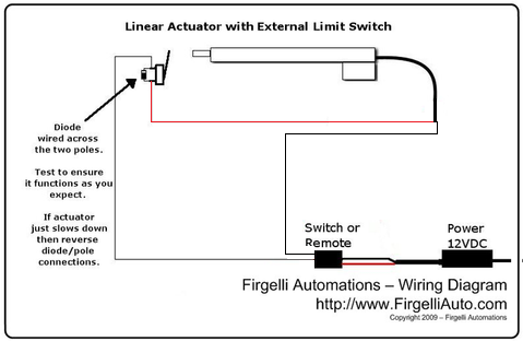
Connect the switch terminals inline with one of the motor leads. The polarity of the connection determines whether the switch limits extension or retraction. Note that the diodes come pre-installed across the switch terminals—do not remove or bypass these components. The optional inline fuses included in the kit can provide additional overcurrent protection but are not mandatory for most applications.
Dual Switch Wiring Configuration
For applications requiring both custom extension and retraction limits, install two switches in the circuit. Each switch controls one direction of travel, with its integrated diode permitting reverse current flow.
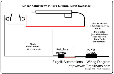
Wire one switch for the extension limit and the second for the retraction limit, ensuring proper polarity for each. This configuration creates a custom operating window within the actuator's full stroke range. Both internal and external limits remain active, providing multiple layers of over-travel protection.
External Limit Switches in Multi-Actuator Systems
In synchronized multi-actuator applications, external limit switches can be integrated into the control box circuit rather than wired directly to individual actuators. This approach is particularly useful when using FIRGELLI SYNC boards or other synchronization controllers that manage multiple actuators simultaneously.
The limit switches can be positioned to monitor the position of any actuator in the array or to detect mechanical conditions in the application itself—such as when a lifting platform reaches a predetermined height or when a sliding mechanism arrives at a specific position. When the switch activates, it interrupts the control signal to all synchronized actuators, bringing the entire system to a coordinated stop.

This control-circuit integration method is especially valuable in applications like adjustable workbenches, multi-column lifts, or coordinated door systems where maintaining synchronization throughout the motion is critical. The external switches provide precise position control while the synchronization system ensures all actuators move in concert, preventing binding, misalignment, or structural stress.
Troubleshooting and Best Practices
Common Installation Issues
If your actuator doesn't stop at the limit switch, verify that the switch is being physically activated—the button should be visibly depressed when the actuator reaches the limit position. Check all electrical connections for continuity and ensure no wires have come loose during installation. Confirm that the switches are wired with correct polarity; reversing the connections will cause the switch to limit the wrong direction of travel.
If the actuator stops at the limit but won't reverse, the diode may be damaged or the switch may be defective. Use a multimeter to test the diode's functionality—it should show continuity in one direction and near-infinite resistance in the other. Replace the switch if the diode is faulty.
Mounting Considerations for Reliability
Switch positioning is critical for consistent performance. Mount switches perpendicular to the direction of actuator motion so the button receives direct, square contact rather than glancing impacts. Angled contact can cause premature wear and inconsistent triggering.
In high-vibration environments, use lock washers or thread-locking compound on mounting hardware to prevent loosening over time. Consider adding a small shock-absorbing pad between the actuator's contact surface and the switch button to reduce impact forces, especially in high-speed or heavy-load applications.
Protect limit switches from environmental contamination. In dusty environments, position switches where debris accumulation is minimal, or use switches rated for harsh environments. In wet conditions, ensure all electrical connections are properly sealed and insulated. Heat shrink tubing provides better protection than electrical tape for most applications.
Integration with Feedback Systems
External limit switches can be used alongside feedback actuators that provide position sensing through potentiometers, Hall effect sensors, or optical encoders. In these hybrid systems, the feedback sensor provides precise position data for control purposes, while the external limit switches serve as hardware-based safety limits that operate independently of the control system.
This redundant approach is particularly valuable in safety-critical applications where software failures or control system malfunctions could result in over-travel. The mechanical limit switches provide a failsafe that functions regardless of control system status.
Real-World Application Examples
Understanding how external limit switches solve practical problems helps clarify their value across different applications. Consider a custom TV lift installation where the television must stop at a viewing position that's less than full extension. Internal limits would allow the TV to rise completely out of the cabinet, but the viewing angle becomes poor at full height. An external limit switch mounted at the optimal viewing position ensures the TV stops exactly where needed.
In automated drawer slide applications, external limits prevent drawers from opening so far that items fall out the back, while also ensuring minimum closure distance for proper latch engagement. Industrial applications often use external limits to create safe zones where human operators can work without risk of pinch points or collisions with moving machinery.
Automotive and marine applications frequently require partial stroke operation to accommodate space constraints or to sequence multiple moving components. A sliding hatch might need to stop before it hits a mast or antenna, or a concealed storage compartment might need to extend only far enough to access contents without interfering with adjacent systems.
Selecting the Right Components for Your Application
While the external limit switch kit is compatible with most FIRGELLI linear actuators, consider your overall system requirements when planning your installation. The current rating of the switches must exceed the actuator's operating current, including the inrush current spike that occurs when the motor starts.
For high-force industrial actuators or applications with rapid cycling, heavy-duty limit switches with higher contact ratings provide longer service life. Conversely, micro linear actuators with low current draw can use lighter-duty switches, potentially reducing system cost and complexity.
Ensure your power supply provides adequate voltage and current for your actuator while accounting for the voltage drop across switches and wiring. In 12V DC systems, wire resistance and switch contact resistance can become significant factors in long cable runs or high-current applications.
Conclusion: Precision Control Through External Limit Switches
External limit switches provide essential flexibility for electric linear actuator applications that require custom travel limits beyond factory-installed internal switches. By understanding the electrical principles behind limit switch operation—particularly the critical role of parallel diodes in maintaining bidirectional control—you can design and implement reliable motion control systems tailored to your specific requirements.
Proper mechanical mounting and electrical connection ensure consistent, repeatable positioning while protecting your actuators and application from over-travel damage. Whether you're building a single-actuator mechanism or a complex multi-actuator synchronized system, external limit switches give you precise control over the operating envelope of your motion system.
Frequently Asked Questions
Do external limit switches override the internal limit switches in my actuator?
No, external limit switches do not override or disable internal limits—they supplement them. The internal limit switches remain active as a backup safety system. If an external limit switch fails or is improperly positioned, the internal limits will still prevent the actuator from exceeding its mechanical stroke length. This layered approach provides redundant protection against over-travel damage. External switches simply create additional stop points within the operating range defined by the internal limits.
Can I use any type of switch for external limits, or do I need the specific kit?
While standard switches can physically interrupt current flow, they lack the parallel diodes necessary for proper bidirectional operation with linear actuators. Without the diode, the actuator would become stuck when the switch activates, unable to reverse direction. The FIRGELLI external limit switch kit includes properly rated switches with pre-installed, correctly oriented diodes, eliminating the need to source and install these components separately. Using standard switches without diodes will result in non-functional or dangerous operation.
How do I determine the correct mounting position for my limit switches?
Install the actuator in its final position and manually cycle it through its range of motion with power disconnected. Mark the exact positions where you want motion to stop—these are your limit positions. The switch should be mounted so its actuating button is contacted by a moving component (shaft bracket, collar, or custom tab) precisely at each limit position. Account for the mechanical travel of the switch button itself, which is typically 3-5mm. Test positioning by slowly moving the actuator to the limit point and verifying that the switch activates at the desired position before final mounting.
What happens if both limit switches are activated simultaneously?
In a properly designed system, both switches should never activate simultaneously, as this would indicate that your custom operating window is smaller than physically possible or that switches are incorrectly positioned. However, if this condition does occur, the actuator will be unable to move in either direction through normal switching—both circuits would be open. The actuator would only become operational again if one switch is mechanically released. This scenario indicates a design or installation error that should be corrected before normal operation.
Can I use external limit switches with wireless remote controls and control boxes?
Yes, external limit switches integrate seamlessly with remote controls and control boxes. The switches are wired in series with the motor circuit, so they function regardless of what type of control system sends power to the actuator. Whether you're using a simple switch, a wireless remote, a programmable controller, or an Arduino-based system, the limit switches operate at the motor level and will override any control input when activated. This ensures consistent position limiting regardless of control method.
How long do external limit switches typically last in continuous-use applications?
Switch longevity depends on actuation frequency, contact current, and environmental conditions. Quality limit switches like those in the FIRGELLI kit are rated for hundreds of thousands to millions of operations under normal conditions. The mechanical components (spring and button) typically outlast the electrical contacts. In high-cycle applications, contact wear gradually increases resistance until the switch no longer reliably interrupts current. Environmental factors like moisture, dust, and extreme temperatures can significantly reduce service life. For critical applications, plan for periodic inspection and replacement based on cycle counts and performance monitoring.


