Controlling Linear Actuator Speed: Methods and Best Practices
The ability to precisely control the speed of a linear actuator is critical for countless automation applications—from smooth TV lifts that need gradual motion to avoid startling viewers, to synchronized standing desk mechanisms that require multiple actuators to move in unison. Without proper speed control, actuators operate at their maximum rated speed, which can cause jerky motion, excessive noise, mechanical stress, and shortened component lifespan.
🎥 Video — How to control the speed of a linear actuator
Understanding how to effectively control actuator speed opens up new possibilities for your automation projects. Whether you're building a custom automation system with an Arduino microcontroller, implementing industrial controls with a PLC, or simply need a straightforward manual speed adjustment solution, there are multiple proven approaches to achieve the precise motion control your application demands.
This comprehensive guide explores the fundamental methods for controlling linear actuator speed, with particular focus on practical implementation using dedicated speed controllers. We'll examine the technical principles behind each approach, provide detailed wiring diagrams and setup instructions, and address common challenges like achieving near-synchronous control of multiple actuators without feedback sensors.
Fundamental Speed Control Methods for Linear Actuators
Before diving into specific implementations, it's important to understand the core technologies available for speed control. Each method offers distinct advantages depending on your application requirements, budget, and technical expertise.
Pulse Width Modulation (PWM)
Pulse Width Modulation represents one of the most efficient and widely-used methods for controlling DC motor speed in linear actuators. PWM works by rapidly switching the power supply on and off at a fixed frequency, while varying the ratio of on-time to off-time (the duty cycle). A 50% duty cycle delivers effectively half the voltage, while a 75% duty cycle delivers three-quarters of the voltage, directly affecting motor speed.
The key advantage of PWM is efficiency—since the control circuit is either fully on or fully off, minimal power is wasted as heat in the switching components. This makes PWM ideal for battery-powered applications and systems requiring extended runtime. Most dedicated actuator speed controllers, including the FIRGELLI FA-SC1, utilize PWM internally to achieve smooth speed variation while maintaining high efficiency.
Variable Voltage Control
The most straightforward approach to speed control involves adjusting the DC voltage supplied to the actuator. Since motor speed is directly proportional to applied voltage, reducing voltage from 12V to 6V will approximately halve the actuator speed. This method can be implemented using variable voltage power supplies, linear regulators, or voltage divider circuits.
While conceptually simple, pure voltage control is less efficient than PWM because voltage reduction through linear methods generates waste heat. However, for low-power micro linear actuators or applications where heat dissipation isn't problematic, voltage control provides a straightforward solution without complex electronics.
Microcontroller and PLC Control
For sophisticated automation projects, external control circuits using microcontrollers (like Arduino, Raspberry Pi) or Programmable Logic Controllers (PLCs) offer maximum flexibility. These systems can generate PWM signals or analog voltage outputs that interface with speed controllers, while also implementing complex logic, sensor integration, and coordinated multi-actuator control.
This approach is particularly valuable when speed must vary dynamically based on sensor feedback, user input, or programmed sequences. Industrial applications frequently employ PLCs to coordinate multiple actuators while monitoring position, load, and safety conditions.
Feedback Control Systems
The most precise speed control involves closed-loop feedback systems where position sensors (typically Hall effect or optical encoders) continuously monitor actuator position and speed. The control system compares actual performance against desired parameters and adjusts drive signals accordingly. Feedback actuators with built-in sensors enable this advanced control, allowing for exact positioning, synchronization of multiple actuators, and compensation for varying loads.
The FIRGELLI FA-SC1 Actuator Speed Controller
The FA-SC1 Actuator Speed Controller provides a practical, cost-effective solution for varying the speed of 12V FIRGELLI linear actuators. This versatile controller uses efficient PWM technology internally while offering multiple control input options—manual DIP switches for fixed speed settings, or external voltage control for dynamic speed adjustment via potentiometers or microcontrollers.
Technical Specifications and Capabilities
The FA-SC1 is designed specifically for single-actuator applications with the following specifications:
- Voltage Rating: 12V DC (compatible with standard 12V linear actuator systems)
- Maximum Current: 10A continuous (sufficient for most standard duty actuators)
- Control Methods: 4-position DIP switch (16 speed settings) or external analog voltage (0-5V or 0-12V)
- Connection Type: Screw terminals for secure, vibration-resistant connections
- PWM Frequency: Optimized for smooth, quiet motor operation
Understanding the current limitation is critical: the 10A maximum means this controller is intended for a single actuator. Even small actuators can draw surge currents exceeding 10A during startup when connected in parallel, which would damage the controller's output stage.
Understanding the FA-SC1 Board Layout and Connections
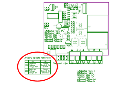
The FA-SC1 features a clear, logical connection layout designed for straightforward installation:
Screw Terminals 1 and 2: Connect directly to your linear actuator motor leads. Polarity determines direction—reversing these connections reverses actuator direction without affecting speed control.
Screw Terminals 3 and 4: Connect to your 12V DC power supply. Ensure your power supply can deliver sufficient current for your actuator's requirements plus a safety margin.
Screw Terminals A and B: Optional external voltage control input (0-5V or 0-12V). Used when controlling speed via potentiometer, microcontroller, or other analog voltage source.
Jumper Pin 1: Selects the external control voltage range. Remove for 5V control signals (typical for Arduino and many microcontrollers), leave connected for 12V control signals.
Jumper Pin 2: Selects control mode. Keep connected for DIP switch control, remove when using external voltage control via terminals A and B.
4-Position DIP Switch: Provides 16 discrete speed settings (2^4 combinations) for manual speed selection without external electronics.
Critical Warnings and Limitations
Before connecting your FA-SC1 speed controller, observe these important precautions to prevent permanent damage:
Never reverse external control voltage polarity. The controller lacks reverse polarity protection on the control input. Connecting positive to terminal B and negative to terminal A will immediately damage the input circuitry. Always verify polarity before applying power.
Use only one actuator per FA-SC1. Connecting multiple actuators in parallel may seem convenient, but the combined inrush current during startup frequently exceeds the 10A maximum rating. This creates an overcurrent condition that can destroy the output transistors. For multiple actuator control, use separate speed controllers for each actuator.
Ensure adequate ventilation. While the FA-SC1 uses efficient PWM control, the output stage still generates heat under continuous operation, particularly at higher currents. Mount the controller in a location with adequate airflow and avoid enclosing it in sealed spaces without ventilation.
Controlling Speed Using DIP Switch Settings
For applications requiring fixed speed operation or infrequent speed changes, the FA-SC1's DIP switch control provides the simplest implementation. This method requires no external components or programming—just set the switches to your desired speed configuration.
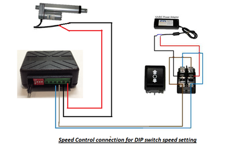
Wiring for DIP Switch Control
To configure the FA-SC1 for DIP switch control:
- Ensure Jumper Pin 2 remains connected (this enables DIP switch mode)
- Connect your actuator leads to screw terminals 1 and 2
- Connect your 12V power supply positive to terminal 3, negative to terminal 4
- Leave screw terminals A and B disconnected (external voltage input not used)
- Set the four DIP switches according to the speed table provided with the controller
Understanding the 16 Speed Settings
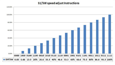
The four DIP switches create 16 unique binary combinations (0000 through 1111), each corresponding to a different speed level. Switch position 1 (all switches off) typically provides the slowest speed, while position 16 (all switches on) delivers maximum speed. The intermediate settings provide logarithmic or linear speed progression depending on the controller's internal calibration.
For optimal results, start with a mid-range setting and adjust incrementally while observing actuator performance. The ideal speed depends on your specific application—slower speeds provide smoother motion and quieter operation but increase cycle time, while higher speeds improve throughput but may cause vibration or excessive noise.
Best Applications for DIP Switch Control
DIP switch control excels in scenarios where speed remains constant during operation:
- TV lift mechanisms where consistent, smooth motion is desired
- Automated access panels requiring reliable, repeatable operation
- Industrial equipment where speed is set during installation and rarely changed
- Marine applications such as hatch or window automation where simplicity enhances reliability
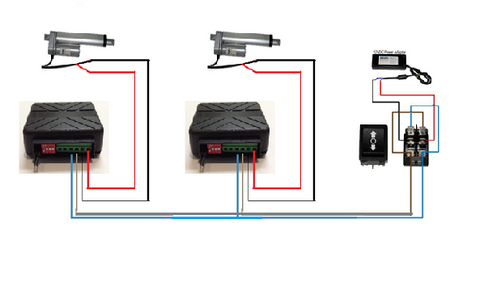
Near-Synchronous Control of Multiple Linear Actuators
Many automation projects require two or more actuators to move simultaneously—lifting opposite ends of a platform, operating dual wing doors, or raising adjustable tables. While feedback actuators with dedicated synchronization controllers (like the FA-SYNC-2 or FA-SYNC-4) provide the most precise solution, projects using standard actuators without position feedback can achieve acceptable synchronization using multiple speed controllers.
Setup and Tuning Procedure
To implement near-synchronous control using FA-SC1 speed controllers:
- Install one FA-SC1 for each actuator in your system
- Connect all controllers to the same 12V power supply (ensure adequate current capacity for simultaneous operation)
- Wire all controllers to the same direction control switch or relay
- Initially set all DIP switches to the same speed setting
- Operate the system and observe actuator synchronization
- Make small incremental adjustments to individual controller DIP switches to fine-tune relative speeds
- Repeat adjustment and testing until actuators move together within acceptable tolerance
Understanding Synchronization Limitations
It's essential to understand that this method provides approximate synchronization only. Without feedback sensors, the system cannot compensate for:
- Manufacturing tolerances causing slight speed variations between nominally identical actuators
- Load differences if actuators support uneven weight distribution
- Mechanical friction variations in mounting and linkages
- Temperature effects that alter motor performance over time
- Cumulative position drift that worsens over repeated cycles
For applications requiring precise synchronization—particularly those involving long stroke lengths, heavy loads, or critical positioning—investing in bullet actuators or other feedback-equipped models with proper synchronization electronics delivers superior results and avoids potential mechanical binding or structural stress from unsynchronized motion.
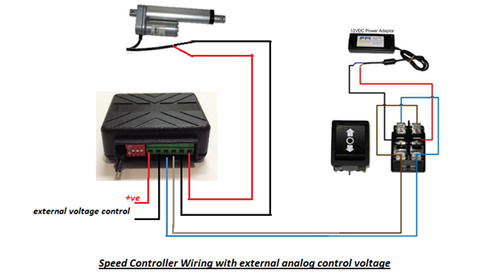
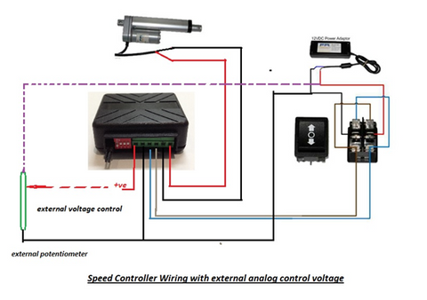
Controlling Speed Using a Potentiometer
For applications requiring user-adjustable speed during operation, potentiometer control offers an intuitive analog interface. This method transforms the FA-SC1 into a variable-speed controller similar to those found in handheld power tools, allowing real-time speed adjustment through a simple rotary knob.
Wiring Configuration for Potentiometer Control
To configure potentiometer control:
- Remove Jumper Pin 2 to disable DIP switch control and enable external voltage input
- Configure Jumper Pin 1 based on your control voltage—remove for 5V operation, leave connected for 12V operation
- Connect a linear potentiometer as a voltage divider: one end to positive control voltage, opposite end to ground, wiper (center terminal) to screw terminal A
- Connect the ground reference to screw terminal B
- Complete standard actuator and power supply connections as previously described
Selecting the Right Potentiometer
Potentiometer selection impacts control feel and reliability:
Resistance Value: Choose 10kΩ to 100kΩ potentiometers. Lower values draw more current from the control voltage source but provide better noise immunity. Higher values minimize loading but may be more susceptible to electrical interference.
Taper: Use linear taper (B-curve) potentiometers for proportional speed response. Audio taper (A-curve) potentiometers provide logarithmic response that feels unnatural for speed control.
Power Rating: Standard 0.25W or 0.5W potentiometers suffice since control current is minimal (under 1mA).
Mounting: Panel-mount potentiometers with integral knobs work well for control panels. Wire-lead types suit prototype or custom installations.
Practical Applications for Potentiometer Control
Potentiometer speed control proves ideal for:
- Manual operator stations where human judgment determines appropriate speed
- Adjustable standing desks allowing users to select preferred transition speeds
- Prototype development enabling easy experimentation with different speeds
- Custom automation projects requiring simple, intuitive user interfaces
Controlling Speed Using Microcontrollers and PLCs
For sophisticated automation requiring programmable, dynamic speed control, interfacing the FA-SC1 with microcontrollers or PLCs unlocks advanced capabilities. This approach enables speed profiles that vary based on sensor inputs, user interfaces, or complex programmed sequences.
Microcontroller Interface Configuration
To connect an Arduino or similar microcontroller:
- Remove Jumper Pin 2 to enable external voltage control mode
- For 5V microcontrollers (Arduino Uno, Nano, Mega), remove Jumper Pin 1
- For 3.3V microcontrollers, use a level shifter to convert to 5V before connecting to the FA-SC1
- Connect the microcontroller's analog output (DAC) or PWM output (filtered to DC) to screw terminal A
- Connect the microcontroller's ground to screw terminal B and to the FA-SC1 power supply ground (ensure common ground reference)
- Complete standard actuator and power supply connections
PWM to Analog Voltage Conversion
Many microcontrollers lack true analog voltage outputs but can generate PWM signals. To convert microcontroller PWM to the analog voltage the FA-SC1 requires, add a simple RC low-pass filter between the PWM output and screw terminal A:
- Connect a 1kΩ resistor in series between the PWM output and terminal A
- Connect a 10µF capacitor between terminal A and ground
- This creates a filter with approximately 16Hz cutoff frequency, smoothing PWM into proportional DC voltage
Set your microcontroller's PWM frequency to at least 1kHz for adequate filtering and smooth speed control response.
Software and Programming Considerations
When programming microcontroller-based speed control:
Implement gradual speed changes by ramping the control voltage rather than making instantaneous jumps. Sudden speed changes cause mechanical shock and excessive current draw.
Add current monitoring if your application approaches the 10A limit or involves variable loads. Many Arduino-compatible current sensors enable load-based speed adjustment or overcurrent protection.
Consider sensor integration to create responsive systems—limit switches for position awareness, temperature sensors for thermal management, or user input devices for interactive control.
Implement fault detection by monitoring stall conditions (current remaining high while control voltage indicates motion should occur) and implementing protective shutdowns or alerts.
PLC Integration for Industrial Applications
When integrating with industrial PLCs:
- Use the PLC's analog output modules (0-10V or 4-20mA types) with appropriate voltage scaling
- Ensure isolation between PLC outputs and actuator power systems if required by safety standards
- Implement proper grounding practices to minimize electrical noise affecting control signals
- Document voltage ranges and calibration procedures in maintenance manuals
- Consider adding indicator lights or HMI displays showing current speed settings for operator awareness
Selecting the Optimal Speed Control Method
Choosing the right speed control approach depends on multiple factors specific to your application. Consider these decision criteria:
Application Complexity and Requirements
Simple fixed-speed applications: DIP switch control provides adequate functionality with minimal complexity. Ideal for TV lifts, access panels, and other single-speed automation.
User-adjustable applications: Potentiometer control suits situations where operators need speed adjustment capability without computer interfaces—adjustable furniture, manual material handling, or prototype development.
Automated systems with logic: Microcontroller or PLC control enables sensor integration, complex motion profiles, and integration with larger automation systems—industrial machinery, robotic systems, or smart home automation.
Precision synchronization: Multiple actuators requiring tight coordination benefit from dedicated feedback actuators with synchronization controllers rather than open-loop speed matching.
Technical Skill Requirements
Honestly assess available expertise:
- DIP switches: Require only basic electrical skills—wire connections and switch settings
- Potentiometers: Need understanding of voltage dividers and proper wiring practices
- Microcontrollers: Demand programming skills, electronics knowledge, and debugging capabilities
- PLCs: Require industrial controls expertise and familiarity with specific PLC programming environments
Budget and Component Availability
Economic factors influence method selection:
Lowest cost: DIP switch control requires only the FA-SC1 controller with no additional components.
Moderate cost: Potentiometer control adds minimal expense (quality potentiometers cost $2-10) while providing enhanced functionality.
Higher initial cost: Microcontroller systems require additional hardware, programming tools, and development time but offer maximum flexibility and upgrade potential.
Troubleshooting Common Speed Control Issues
Actuator Not Moving
If your actuator remains stationary:
- Verify proper voltage at power supply terminals (should read 12V DC)
- Check all screw terminal connections are tight and secure
- Confirm jumper pin settings match your control method
- For external voltage control, measure voltage at terminals A and B (should vary from 0V to reference voltage based on control input)
- Test actuator directly with power supply to confirm it functions properly
Erratic or Inconsistent Speed
Speed variations may indicate:
- Inadequate power supply current capacity causing voltage sag under load
- Loose wiring connections creating intermittent contact
- Electrical noise on control voltage inputs (add decoupling capacitors near terminals A and B)
- Failing potentiometer with worn resistive element (replace potentiometer)
- Mechanical binding in the actuator or driven mechanism (check for obstructions and proper lubrication)
Controller Overheating
Excessive heat generation suggests:
- Operating current approaching or exceeding 10A maximum rating
- Inadequate ventilation around controller mounting location
- Prolonged continuous operation at high current levels
- Consider switching to higher-capacity industrial actuators with lower current draw or add forced air cooling
Multiple Actuators Losing Synchronization
When synchronized actuators gradually diverge:
- This represents expected behavior for open-loop control systems without feedback
- Fine-tune individual speed controller settings for better matching
- Reduce load imbalances between actuators if possible
- Add physical stops or limit switches to periodically re-home actuator positions
- For critical applications, upgrade to feedback actuators with proper synchronization control
Conclusion
Effective speed control transforms linear actuators from simple on-off devices into sophisticated motion control components capable of smooth, precise operation across diverse applications. Whether implementing straightforward DIP switch control for consistent automated operation, potentiometer-based user adjustment for interactive systems, or advanced microcontroller integration for intelligent automation, the fundamental principles remain consistent: proper wiring, appropriate component selection, and understanding the limitations of each approach.
The FIRGELLI FA-SC1 speed controller provides a versatile, cost-effective foundation for most 12V actuator speed control requirements, supporting multiple control methods within a single compact package. For applications demanding precise multi-actuator synchronization or advanced position control, transitioning to feedback actuators with dedicated control electronics delivers superior performance and reliability.
Success ultimately depends on matching control methodology to application requirements—balancing complexity, cost, performance, and available technical expertise to create robust, reliable motion control systems that meet project objectives while remaining maintainable and upgradeable for future needs.
Frequently Asked Questions
How many actuators can I control with a single FA-SC1 speed controller?
The FA-SC1 is designed to control only one linear actuator. The 10A maximum current rating may seem sufficient for multiple small actuators, but startup surge currents from even two actuators frequently exceed this limit, causing permanent damage to the controller's output stage. For multi-actuator applications, use separate speed controllers for each actuator. If precise synchronization is required, consider upgrading to feedback actuators with dedicated multi-channel synchronization controllers like the FA-SYNC-2 or FA-SYNC-4.
Can I use the FA-SC1 with 24V linear actuators?
No, the FA-SC1 is specifically designed for 12V systems and is not compatible with 24V linear actuators. Applying 24V will damage the controller's internal components. For 24V actuator applications, FIRGELLI offers dedicated 24V control solutions. Always verify voltage compatibility between your power supply, controller, and actuator before making connections.
Why does my actuator stall or struggle at very low speeds?
At extremely low speed settings, DC motors receive insufficient voltage to overcome static friction and mechanical resistance, particularly under load. This phenomenon, called "cogging," occurs because the reduced voltage cannot generate adequate starting torque. If your application requires very slow, smooth motion under load, consider using linear actuators with higher gear ratios that operate at higher speeds while delivering slower output motion, or explore servo-controlled actuator options designed for precise low-speed operation.
What voltage should I use for external control—5V or 12V?
The choice depends on your control signal source. Use 5V mode (Jumper Pin 1 removed) when controlling from microcontrollers like Arduino, Raspberry Pi, or other 5V logic devices. Use 12V mode (Jumper Pin 1 connected) when using 12V potentiometers, PLCs with 12V analog outputs, or other 12V control signals. The controller scales the input voltage range to provide full speed control regardless of mode selected. Never apply 12V control signals with the controller configured for 5V mode, as this will damage the input circuitry.
Can I achieve perfect synchronization between actuators without feedback sensors?
No, perfect synchronization is impossible with open-loop control systems that lack position feedback. Manufacturing tolerances, load variations, friction differences, and temperature effects create speed variations that accumulate over time, causing actuators to drift out of sync. The speed controller method described here provides approximate synchronization suitable for applications with reasonable tolerances—furniture, access panels, or platforms where minor position differences are acceptable. Applications requiring precise synchronization—particularly those with long strokes, heavy loads, or critical positioning requirements—should use feedback actuators with built-in position sensors and dedicated synchronization electronics that continuously monitor and correct position differences.


