Understanding Backdrive in Linear Actuators
Backdrive is a critical consideration when designing motion control systems with linear actuators. When an actuator is unpowered, external forces acting on the load can cause the actuator shaft to retract or extend unintentionally—a phenomenon known as backdriving. This occurs because the internal mechanical components, particularly the gearbox and lead screw assembly, can be forced to rotate in reverse when subjected to sufficient force. Understanding and preventing backdrive is essential for applications where maintaining position under load is critical, such as TV lifts, medical equipment, automotive hatches, and industrial positioning systems.
The susceptibility to backdrive varies significantly across different actuator designs. Some linear actuators incorporate self-locking mechanisms through their gear ratios and lead screw pitch, making them inherently resistant to backdriving. Others, particularly those designed for higher speed or smoother operation, may use lower gear ratios or more efficient drive mechanisms that make them more vulnerable to external forces when unpowered. Models like the Deluxe Rod and IP66 Heavy Duty Rod actuators can be back-driven under sufficient force, making backdrive prevention techniques necessary for certain applications.
This tutorial explores proven methods for preventing or minimizing backdrive in electric linear actuators, with particular focus on cost-effective solutions that can be implemented in both DIY and professional installations. Whether you're building a custom automation project or designing commercial equipment, these techniques will help ensure your actuators maintain position reliably under all operating conditions.
What Causes Actuator Backdrive
Backdrive occurs due to the interaction between external mechanical forces and the actuator's internal drive mechanism. When an actuator is powered, the DC motor actively drives the gearbox, which in turn rotates the lead screw or ball screw to extend or retract the shaft. The motor's electromagnetic torque easily overcomes any resistance from the load. However, when power is removed, the motor no longer provides this holding torque, and the system's ability to resist external forces depends entirely on the mechanical efficiency of the gear train and lead screw assembly.
Several factors influence an actuator's resistance to backdrive. The gear ratio plays a significant role—higher gear ratios typically provide more resistance to backdriving because they create a mechanical advantage that works in both directions. The lead screw pitch is equally important; finer-pitch screws with greater thread engagement offer more resistance than coarse-pitch designs. Additionally, the efficiency of the gearbox itself matters: lower-efficiency worm gears tend to be more self-locking than high-efficiency planetary or spur gear systems.
The magnitude of the external force is the ultimate determining factor. Even actuators with good backdrive resistance can be overcome by sufficiently large loads. In applications involving gravity loads, such as vertical lifts or tilting mechanisms, the constant downward force creates continuous pressure on the actuator's mechanical components. If this force exceeds the static friction and mechanical resistance within the drive train, the actuator will begin to backdrive, potentially causing the load to drop or the mechanism to collapse.
Back EMF Braking with SPDT Relay
The most cost-effective and widely applicable solution for preventing actuator backdrive is implementing a back EMF (electromotive force) braking system using a simple SPDT (Single-Pole, Double-Throw) relay. This elegant solution leverages the physical principle that a DC motor, when forced to rotate by an external force, acts as a generator producing voltage. By strategically wiring a relay to short-circuit the motor terminals when unpowered, you create an electrical braking effect that provides substantial resistance to backdriving.
How Back EMF Braking Works
When an external force attempts to backdrive an unpowered actuator, it forces the internal DC motor to rotate. As the motor's rotor spins within its magnetic field, it generates a small voltage—this is the back EMF. In a normal unpowered state with open motor terminals, this voltage has nowhere to go and produces minimal resistance to the backdriving force. However, when the motor terminals are shorted together through a closed relay, the back EMF drives current through this closed loop of wire.
This circulating current creates its own magnetic field within the motor, which opposes the motion that created it—a phenomenon described by Lenz's Law. The opposing magnetic field generates a braking torque that resists the rotation of the motor shaft. The faster the attempted backdrive, the stronger the back EMF voltage, and consequently the stronger the braking effect. This creates a self-regulating braking system that automatically adjusts its resistance based on the applied force.
Wiring Configuration and Component Selection
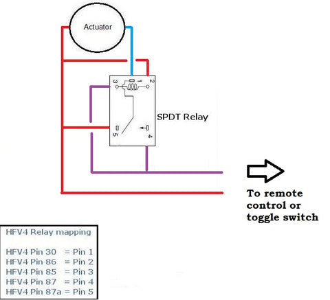
The relay configuration requires careful attention to achieve proper operation. The relay coil should be connected in parallel with the actuator's motor terminals, so that when voltage is applied to drive the actuator, the relay coil is also energized. The relay's normally closed (NC) contacts are wired to short the motor terminals together. When power is applied, the energized relay opens these NC contacts, allowing normal motor operation. When power is removed, the relay de-energizes, and the NC contacts close, shorting the motor terminals and activating the back EMF brake.
Selecting an appropriate relay is crucial for reliable operation. The relay coil voltage must match your actuator's operating voltage—typically 12V or 24V DC for most linear actuators. The contact current rating should exceed the actuator's stall current to prevent contact welding or degradation. A standard automotive-style relay with 30A contacts is suitable for most applications. For micro linear actuators with lower current draw, smaller relays with 10-15A ratings may suffice.
This braking method offers several advantages beyond its low cost. It requires no external power supply beyond what's already driving the actuator, adds minimal complexity to the control circuit, and provides proportional braking force that scales with the attempted backdrive speed. The system is also fail-safe in one important respect: if the relay fails in its de-energized state, the brake remains engaged, preventing uncontrolled movement of the load.
Limitations and Considerations
While back EMF braking is highly effective, it's important to understand its limitations. The braking force is not absolute—extremely large external forces can still overcome the electromagnetic resistance. The technique works best with actuators that already have some inherent backdrive resistance from their gear design. For applications with very heavy loads or critical safety requirements, additional mechanical locking mechanisms may be necessary as redundant safeguards.
The relay contacts must be rated for the switching frequency of your application. In systems where the actuator operates frequently, relay life becomes a consideration, and solid-state relays or contactors may offer better longevity. Additionally, the inductive nature of the motor and relay coils can generate voltage spikes during switching, so incorporating flyback diodes across the relay coil is recommended to protect control electronics and extend relay life.
Gas Spring Support Systems
An alternative mechanical approach to preventing backdrive involves using gas springs (also called gas struts or gas shocks) in parallel with the linear actuator. This method is particularly effective for applications involving vertical lifting or tilting movements where gravity creates a constant downward force. By selecting a gas spring with appropriate force characteristics, you can offset the weight of the load, reducing or eliminating the net force trying to backdrive the actuator when unpowered.
Gas Spring Selection Criteria
Proper gas spring selection requires careful calculation of forces and geometry. The gas spring must generate sufficient force to counterbalance the load throughout the actuator's entire stroke length. However, it shouldn't be so strong that it creates excessive opposition during powered actuation, which would require a more powerful actuator and increase power consumption. The ideal configuration has the gas spring providing 80-95% of the force needed to hold the load, allowing the actuator's internal friction and back EMF to handle the remaining 5-20%.
Gas spring force varies with position due to the compression and expansion of the gas charge. This force curve must be mapped against your application's requirements throughout the full range of motion. The mounting geometry also affects the effective force—gas springs mounted at angles provide less support force than when mounted in-line with the load movement. These geometric considerations require careful attention during the design phase to ensure adequate support without over-constraining the system.
Installation and Integration
Installing gas springs in parallel with linear actuators requires adequate mounting points and sufficient space for both components. The gas spring should be mounted as close to parallel with the actuator as possible to maximize efficiency and minimize side loading. Standard mounting brackets may need modification or custom fabrication to accommodate both the actuator and gas spring attachment points.
One significant advantage of this approach is its fail-safe behavior. If the actuator fails electrically or mechanically, the gas spring continues to support the load, preventing sudden collapse. This makes gas spring assistance particularly valuable in applications where load drops pose safety risks, such as overhead panels, medical beds, or automotive tailgates. The system also reduces wear on the actuator by sharing the load-bearing duty, potentially extending actuator service life.
Limitations and Trade-offs
The gas spring approach has several drawbacks to consider. The most obvious is the additional cost and complexity of sourcing, installing, and maintaining a separate mechanical component. Gas springs must be purchased from third-party suppliers, as FIRGELLI Automations does not manufacture them, requiring attention to compatibility with actuator dimensions and mounting interfaces.
Gas springs also introduce force that must be overcome during powered actuation. This means your actuator must be sized to handle both the application load and the gas spring resistance, potentially requiring a higher-capacity actuator than would otherwise be necessary. Additionally, gas springs can lose pressure over time, gradually reducing their support force and potentially allowing backdrive to occur as they age. Regular inspection and eventual replacement become necessary maintenance tasks.
Temperature sensitivity is another consideration—gas springs change their force characteristics with temperature variations, which may affect system performance in environments with wide temperature swings. For precision applications or those requiring consistent behavior across varying conditions, this variability may be problematic.
Comparing Backdrive Prevention Methods
When choosing between back EMF braking and gas spring support, several factors should guide your decision. Back EMF braking offers the most cost-effective solution for general applications, requiring only a relay and simple wiring modifications. It adds minimal weight and bulk to the installation, making it ideal for space-constrained applications or those where weight is critical. The electrical approach also provides consistent performance across temperature ranges and doesn't degrade over time like mechanical components.
Gas spring support excels in applications with heavy vertical loads where fail-safe behavior is paramount. The mechanical redundancy provides peace of mind in safety-critical applications, and the load-sharing reduces stress on the actuator system. However, the additional cost, installation complexity, and maintenance requirements make it more suitable for applications where the safety benefits justify the extra investment.
For maximum protection in critical applications, combining both methods offers redundant safeguards. The back EMF brake provides primary holding force during normal operation, while the gas spring serves as a mechanical backup that maintains load support even if electrical systems fail completely. This belt-and-suspenders approach is common in medical equipment, accessible furniture, and industrial automation where load drops could cause injury or equipment damage.
Application-Specific Considerations
Different application types present unique challenges for backdrive prevention. In TV lift systems, the combined weight of the television and mounting hardware creates substantial force that increases as the TV reaches full extension due to the cantilevered load. Back EMF braking typically provides sufficient holding force for residential applications with televisions up to 65 inches, while larger commercial displays may benefit from gas spring assistance.
For standing desk applications, the desktop load remains relatively constant throughout the range of motion, making them ideal candidates for back EMF braking alone. The horizontal load components are minimal, and the actuators primarily work against gravity in a predictable manner. Dual or quad actuator configurations benefit particularly from back EMF braking because it ensures all actuators remain synchronized even when unpowered, preventing racking or binding.
Industrial actuators in manufacturing and automation equipment often face varying loads and may be subject to external forces from conveyor systems, robotic arms, or process equipment. These applications may require the most robust backdrive protection, potentially combining electrical braking with mechanical locking mechanisms or brakes integrated into the actuator itself. For high-cycle applications, the durability of relay contacts becomes critical, and solid-state switching may be preferable.
Alternative Solutions and Advanced Techniques
Beyond the two primary methods discussed, several other approaches can prevent or mitigate backdrive in specific scenarios. Some feedback actuators can be paired with closed-loop control systems that actively monitor position and apply corrective power when movement is detected. This active holding technique provides precise position maintenance but requires continuous power consumption and more sophisticated control electronics.
Mechanical brakes or locking mechanisms can be integrated into custom actuator installations. Spring-set, electrically released brakes similar to those used in servo motors provide positive locking when unpowered and release automatically when voltage is applied. These add significant cost and complexity but offer absolute position holding regardless of external forces. Ratchet mechanisms or pawl-and-gear systems provide unidirectional locking for applications where preventing movement in only one direction is necessary.
For applications using Arduino or other microcontroller-based control systems, software-based approaches can enhance backdrive prevention. Programming the controller to pulse the actuator motor periodically when position sensors detect creep can counteract gradual backdriving before it becomes significant. This technique works well with feedback actuators that provide position information, allowing the control system to detect and correct any unwanted movement.
Troubleshooting Backdrive Issues
If an actuator continues to backdrive despite implementing prevention measures, systematic diagnosis can identify the root cause. First, verify that the back EMF braking relay is functioning correctly by measuring continuity across the motor terminals when unpowered—you should see a short circuit indicating the NC contacts are closed. If the relay coil isn't energizing during normal operation, check voltage at the coil terminals and verify proper wiring connections.
Insufficient holding force from back EMF braking may indicate that the load exceeds the actuator's backdrive resistance capacity. Calculate the actual forces in your application, accounting for factors like friction, leverage, and dynamic loads during motion. If forces are higher than anticipated, consider upgrading to an actuator with better inherent backdrive resistance or adding gas spring support to share the load.
For gas spring installations experiencing backdrive, verify the spring is properly charged and providing its rated force. Gas springs can be tested with a force gauge to confirm output matches specifications. Check mounting angles and geometry to ensure the gas spring provides force in the correct direction and isn't being overcome by mechanical advantage working against it. Worn or damaged gas springs should be replaced as they cannot be recharged in the field.
In some cases, backdrive issues stem from excessive friction or binding in the mechanical system rather than insufficient holding force. Misaligned mounting brackets, bent actuator shafts, or inadequate load guidance can create side loads that overcome the actuator's resistance. Inspect all mounting brackets for proper alignment and consider adding linear bearings or slide rails to guide heavy loads and reduce side loading on the actuator.
Conclusion
Preventing backdrive in linear actuators requires understanding the mechanical and electrical principles at work and selecting appropriate countermeasures for your specific application. Back EMF braking with an SPDT relay provides an elegant, cost-effective solution suitable for most residential and light commercial applications. Gas spring support offers mechanical redundancy and fail-safe behavior for heavier loads and safety-critical installations. By carefully analyzing your application's force requirements, safety considerations, and operating environment, you can implement the most appropriate backdrive prevention strategy to ensure reliable, safe operation of your linear motion system.
Frequently Asked Questions
What is backdrive in a linear actuator?
Backdrive occurs when external forces applied to an unpowered linear actuator cause the shaft to retract or extend unintentionally. This happens because the actuator's internal motor and gearbox can be forced to rotate in reverse when sufficient force is applied. The phenomenon is similar to pushing a car in neutral—without the engine providing resistance, the wheels (or in this case, the actuator shaft) can move freely if enough force is applied. Backdrive is most problematic in vertical lifting applications where gravity constantly pulls on the load, but it can occur in any orientation if external forces are large enough.
Why does back EMF braking work to prevent actuator backdrive?
Back EMF braking works because a DC motor acts as a generator when forced to rotate by external forces. When the motor terminals are shorted together through a relay's normally closed contacts, the voltage generated by this forced rotation drives current through the closed loop of wire. This current creates a magnetic field that opposes the motion causing it, generating a braking torque that resists the backdriving force. The faster the attempted backdrive, the stronger the back EMF and the greater the braking effect, making it a self-regulating system that automatically provides more resistance when needed.
What size relay do I need for back EMF braking?
The relay coil voltage must match your actuator's operating voltage, typically 12V DC or 24V DC. The contact current rating should exceed the actuator's stall current to prevent contact damage—a standard automotive relay with 30-40A contacts works well for most full-size linear actuators. For micro actuators with lower current draw (under 5A), smaller relays rated for 10-15A are sufficient. Always verify the actuator's current specifications and select a relay with at least 50% margin above the maximum current to ensure long service life and reliable operation.
Can I use gas springs instead of back EMF braking?
Yes, gas springs offer an alternative mechanical approach to preventing backdrive, particularly effective for vertical lifting applications with heavy loads. Gas springs provide constant support force that counterbalances the weight, reducing the net force trying to backdrive the actuator. However, this method requires additional mounting space, increases system complexity, and adds cost compared to back EMF braking. The actuator must also be sized to overcome the gas spring force during powered operation. Gas springs excel in applications requiring fail-safe behavior where mechanical redundancy is important, but for most residential applications, back EMF braking offers a simpler, more cost-effective solution.
Should I use both back EMF braking and gas springs together?
Using both methods together provides maximum protection and is recommended for safety-critical applications where load drops could cause injury or significant equipment damage. The back EMF brake serves as the primary holding mechanism during normal operation, while the gas spring provides mechanical backup support if electrical systems fail. This redundant approach is common in medical equipment, heavy-duty TV lifts supporting expensive displays, and industrial applications with overhead loads. However, for typical residential or light commercial use, either method alone usually provides adequate protection, and the decision should be based on your specific safety requirements, budget constraints, and installation space availability.
Which FIRGELLI actuators have the best backdrive resistance?
Actuator backdrive resistance depends primarily on gear ratio and lead screw design. Models with higher gear ratios and finer-pitch lead screws generally offer better inherent resistance to backdriving. Industrial actuators typically incorporate design features that enhance backdrive resistance, while track actuators and bullet actuators optimized for speed may have lower backdrive resistance due to their more efficient drive mechanisms. For applications where backdrive prevention is critical, consult the specific actuator's technical specifications or contact FIRGELLI's technical support to discuss your load requirements and determine whether additional backdrive prevention measures will be necessary for your chosen model.


