Introduction: Motion Detection and Linear Actuator Integration
Motion detection technology has evolved far beyond its traditional role in security systems and automated lighting. When paired with electric linear actuators, motion sensors open up a world of possibilities for interactive automation, from sophisticated haunted house effects to responsive home automation systems. The combination of motion sensing input with precise linear motion control creates dynamic systems that react intelligently to their environment.
For engineers and DIY enthusiasts alike, understanding how to integrate motion detectors with linear actuators provides a foundation for building responsive, automated systems. Whether you're designing a security-activated hidden compartment, a motion-triggered display system, or an interactive art installation, the principles remain consistent: detect movement, process the signal, and control actuator motion accordingly. This guide covers the technical fundamentals, sensor selection criteria, and practical implementation strategies for creating reliable motion-activated linear actuator systems.
The versatility of this technology combination extends across multiple applications. Haunted attractions use motion-triggered actuators for perfectly timed jump scares. Retail displays employ them for interactive product demonstrations. Smart homes integrate them for automated furniture, hidden storage, and adaptive accessibility features. Understanding the capabilities and limitations of different sensor types, along with proper control implementation, is essential for designing systems that perform reliably in real-world conditions.
Understanding Motion Detector Technologies
Motion detectors operate on various physical principles, each with distinct advantages for different applications. The most common types used in actuator control systems are passive infrared (PIR), microwave, and ultrasonic sensors. Understanding the operational characteristics of each type helps you select the right sensor for your specific application requirements.
Passive Infrared (PIR) Sensors
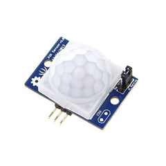
Passive infrared sensors detect changes in infrared radiation, which all objects emit based on their temperature. When a warm body—such as a person or animal—moves through the sensor's field of view, the PIR sensor detects the change in infrared energy and triggers an output signal. PIR sensors are "passive" because they don't emit any energy themselves; they simply observe infrared radiation in their environment.
PIR sensors offer several advantages for actuator control applications. They consume minimal power, typically operating on 5-12VDC with current draw under 50mA. Their detection range typically extends from 3 to 12 meters, with adjustable sensitivity on many models. The field of view varies by lens configuration, with most sensors offering 90 to 120-degree coverage angles. PIR sensors work best in indoor environments where temperature differentials between moving objects and background remain relatively stable.
Most PIR sensors include adjustment potentiometers for sensitivity and time delay. Sensitivity adjustment controls how much infrared change triggers detection, useful for filtering out small animals or distant movement. Time delay determines how long the output signal remains high after detecting motion, typically adjustable from a few seconds to several minutes. These adjustments allow you to tune sensor behavior for specific applications without modifying your control code.
Microwave and Ultrasonic Sensors
Microwave sensors emit electromagnetic waves and detect reflections off moving objects using the Doppler effect. Unlike PIR sensors, microwave sensors can detect motion through non-metallic materials like wood, plastic, or drywall, making them suitable for concealed installations. However, they consume more power than PIR sensors and can be triggered by small movements like swaying plants, requiring careful positioning.
Ultrasonic sensors emit high-frequency sound waves and measure reflections to detect motion. They work well in enclosed spaces and aren't affected by temperature variations like PIR sensors. Ultrasonic sensors excel at detecting movement regardless of the object's temperature, making them suitable for detecting moving machinery or objects rather than just living beings. However, soft materials like fabric can absorb ultrasonic waves, potentially creating blind spots in the detection field.
For most hobbyist and DIY applications involving linear actuators, PIR sensors provide the best balance of cost, ease of use, and reliability. They're readily available, require minimal supporting circuitry, and integrate easily with microcontroller platforms like Arduino. The remainder of this guide focuses primarily on PIR sensor integration, though the control principles apply broadly across sensor types.
Area Reflective and Specialized Sensors
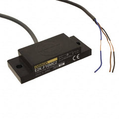
Area reflective sensors use infrared light emitted by the sensor itself (unlike passive PIR sensors) and detect reflections off nearby objects. These sensors typically have shorter range than PIR sensors but can provide more precise detection zones. Vibration sensors detect physical vibrations in surfaces or structures, useful for detecting footsteps or impacts. While less common for general motion detection, these specialized sensors suit specific applications where standard motion detection proves inadequate.
Proximity Sensors Versus Motion Detectors: Understanding the Difference
It's important to distinguish between proximity sensors and motion detectors, as they serve fundamentally different purposes despite sometimes producing similar results. Motion detectors specifically respond to movement—they remain inactive when objects are stationary, regardless of proximity. Proximity sensors, conversely, measure how close an object is to the sensor, detecting presence rather than movement. A proximity sensor continues signaling as long as an object remains within its detection range, moving or not.
This distinction matters significantly for actuator control applications. If you need an actuator to extend when someone approaches and retract when they leave, a proximity sensor may be more appropriate than a motion detector. However, if the actuator should respond to movement but ignore stationary objects—such as in a security application—a motion detector is the correct choice.
Proximity sensors can function as crude motion detectors since their output changes when an object moves into or out of detection range. However, they only detect the closest object in their sensing path. If something moves behind a stationary object that's already within detection range, the proximity sensor won't detect this secondary movement. This limitation makes proximity sensors less suitable for general motion detection compared to dedicated motion sensors.
Common proximity sensor types include inductive (for metal detection), capacitive (for various materials), ultrasonic (distance measurement), and photoelectric (optical detection). Each type has specific strengths: inductive sensors excel at detecting metal components in industrial settings, while ultrasonic sensors provide accurate distance measurement for feedback actuators requiring precise position control. When designing your motion-activated system, consider whether you need to detect movement specifically or simply respond to object presence.
System Architecture and Control Strategy
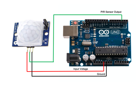
Creating a reliable motion-activated linear actuator system requires proper system architecture that accounts for sensor characteristics, control logic, and actuator specifications. The typical architecture consists of three main components: the motion sensor (input device), a microcontroller or control system (processing), and the linear actuator with its driver circuitry (output device).
Microcontroller Selection and Setup
A microcontroller serves as the system brain, reading sensor inputs and controlling actuator motion based on your programmed logic. Arduino platforms are popular for DIY applications due to their accessibility and extensive community support. When selecting a microcontroller, consider the number of I/O pins required, processing speed for your control logic, and availability of interrupt pins for responsive motion detection.
Most PIR sensors output a simple digital signal: high voltage (typically 3.3V or 5V) when motion is detected, low voltage (0V) when no motion is present. This binary output connects directly to digital input pins on your microcontroller without requiring analog-to-digital conversion or signal conditioning. The simplicity of this interface makes PIR sensors particularly suitable for hobbyist projects and rapid prototyping.
For reliable operation, ensure your microcontroller and motion sensor share a common ground connection. The PIR sensor requires power, typically 5-12VDC depending on the specific module, which may come from the microcontroller's voltage regulator or an external power supply. Check your sensor's specifications to verify voltage requirements and maximum current draw to avoid overloading your microcontroller's voltage regulator.
Motor Driver and Actuator Interface
Microcontrollers cannot directly drive linear actuators because actuators require significantly more current than microcontroller pins can source. A motor driver acts as an intermediary, taking low-power control signals from the microcontroller and switching high-power current to the actuator motor. Common motor driver options include H-bridge motor drivers, relay modules, and dedicated motor control ICs.
H-bridge motor drivers allow bidirectional control, enabling you to extend and retract the actuator by reversing polarity. Most H-bridge modules require at least two control signals: one for direction and one for enable/speed control via PWM. Relay-based control offers a simpler alternative using mechanical relays to switch actuator power, though relays have slower switching times and limited cycle life compared to solid-state drivers.
When sizing your motor driver, ensure it can handle your actuator's current requirements with adequate safety margin. Most micro linear actuators draw 1-3A at 12V, while larger industrial actuators may require 5-10A or more. Select a motor driver rated for at least 150% of your actuator's maximum current draw to ensure reliable operation and thermal performance.
Power Supply Considerations
Motion-activated actuator systems typically require two voltage levels: low voltage for the microcontroller and sensor (3.3-5VDC) and higher voltage for actuator operation (12-24VDC typically). You can use the microcontroller's onboard voltage regulator to power the PIR sensor if current draw remains within limits, or provide separate regulated power for the sensor.
The actuator requires a dedicated power supply rated for continuous operation at the actuator's voltage and current specifications. Calculate total current requirements by adding actuator current, motor driver quiescent current, and any additional loads. Select a power supply with at least 20% overhead capacity to accommodate inrush current during motor startup and ensure reliable operation under varying load conditions.
Implementing Motion Detection with Interrupts
Your control code can read motion sensor output using two primary methods: continuous polling in the main program loop or external hardware interrupts. Understanding both approaches helps you select the most appropriate method for your application requirements.
Polling Versus Interrupt-Driven Detection
Polling involves repeatedly checking the sensor's output state in your main program loop. This approach is simple to implement and understand, requiring only a digital input read operation. However, polling can miss brief motion detection events if the main loop is executing other tasks when motion occurs. If your code includes delays or time-consuming operations, the sensor might trigger and reset before your next polling cycle reads the state.
External interrupts provide a more robust solution for critical motion detection applications. An interrupt is a hardware feature that immediately executes a special function (interrupt service routine) when a voltage change occurs on a designated pin, regardless of what the main program is doing. This ensures your system responds to motion detection instantly without missing events, even if the main loop is busy with other tasks.
Most Arduino boards provide multiple interrupt-capable pins. For example, Arduino Uno has two external interrupt pins (digital pins 2 and 3), while Arduino Mega offers six. Consult your specific microcontroller's documentation to identify available interrupt pins and their configuration options. Connect your PIR sensor output to one of these interrupt pins to implement interrupt-driven motion detection.
Configuring Interrupt Service Routines
Setting up an external interrupt requires three steps: designate an interrupt pin, configure the trigger condition, and write the interrupt service routine (ISR). The trigger condition determines when the interrupt fires—common options include RISING (low to high transition), FALLING (high to low transition), CHANGE (any transition), or LOW (continuous low state).
For PIR sensor integration, RISING trigger mode works well since you want to detect when the sensor transitions from no motion (low) to motion detected (high). The ISR should be brief and fast-executing, typically just setting a flag variable that your main loop checks to determine appropriate action. Avoid complex operations, delays, or serial communication within ISRs as these can cause timing issues and system instability.
Here's a typical interrupt configuration for PIR motion detection:
Setup code: Attach the interrupt to the designated pin, specify RISING trigger mode, and point to your ISR function. ISR function: Set a boolean flag indicating motion was detected. Main loop: Check the flag and execute actuator control logic when motion is detected, then reset the flag for the next detection event.
Debouncing and False Trigger Prevention
Motion sensors, particularly PIR sensors, can produce multiple rapid triggers from a single motion event due to the way they process infrared changes. To prevent erratic actuator behavior, implement debouncing logic that ignores additional triggers for a specified period after the initial detection. This can be accomplished with a timer variable that records when motion was last detected and ignores new triggers until sufficient time has elapsed.
Environmental factors can cause false triggers: sunlight changes, heat sources like HVAC vents, reflective surfaces, or even insects passing close to the sensor. During installation and testing, observe your sensor's behavior in the actual operating environment. Many PIR modules include sensitivity and time-delay adjustments—tune these potentiometers to minimize false triggers while maintaining reliable detection of intended motion.
Practical Control Implementations
The way you translate motion detection into actuator control depends entirely on your application requirements. Two common implementation patterns serve as foundations for most motion-activated actuator systems: trigger-based control and toggle-based control.
Trigger-Based Control for Sequential Actions
Trigger-based control executes a predetermined sequence whenever motion is detected, then resets to wait for the next trigger. This pattern suits applications like haunted house animatronics, where an actuator should extend when motion is detected, hold position briefly, then retract and reset for the next visitor.
Implementation involves setting a motion detection flag when the sensor triggers, then executing a timed sequence: extend the actuator, wait for a specified duration while the flag remains set, retract the actuator, and clear the flag. During the sequence, ignore additional motion detection triggers to prevent interrupting the current sequence. This approach ensures consistent, repeatable actuator behavior regardless of how long motion continues in the sensor's field of view.
The timing values in trigger-based control significantly affect user experience. For a jump-scare application, a short extension time (1-2 seconds) creates sudden surprise, while a longer hold period (10-15 seconds) before reset ensures visitors have passed before reactivating. Test timing values in realistic conditions to optimize performance for your specific application.
Toggle-Based Control for Stateful Applications
Toggle-based control changes actuator state with each motion detection event: first detection extends the actuator, second detection retracts it, third extends again, and so on. This pattern works well for home automation applications like motion-activated hidden storage, adjustable shelving, or automated privacy screens.
Implementation requires tracking actuator state (extended or retracted) and toggling this state each time motion is detected. Include a lockout timer that prevents rapid toggling if someone passes through the sensor field multiple times in quick succession. Without this lockout, the actuator might repeatedly start and stop, creating erratic behavior and potentially damaging the actuator mechanism through excessive cycling.
For toggle-based control, consider using feedback actuators that provide position information. Feedback allows your control system to verify the actuator has reached the intended position before accepting another toggle command, preventing state confusion if the actuator is manually stopped or encounters an obstacle mid-travel.
Advanced Control with Position Feedback
Basic motion-activated systems rely on time-based control, extending the actuator for a predetermined duration then assuming it reached full extension. This approach has limitations: if the actuator encounters resistance or operates under varying loads, final position may be inconsistent. Feedback actuators solve this problem by providing real-time position data.
Common feedback types include potentiometric feedback (analog voltage proportional to position), hall-effect feedback (digital pulses counting position increments), and optical encoders (high-resolution position tracking). Integrating position feedback with motion detection allows sophisticated control strategies: extend to a specific position rather than just "fully extended," adjust position based on previous movement history, or implement soft-start and soft-stop motion profiles for smooth operation.
Position feedback also enables safety features. Your control logic can monitor actuator speed and stop movement if speed drops below expected values, indicating an obstruction. For applications where people might be in the actuator's path, this obstruction detection prevents injury and equipment damage. External limit switches can provide additional safety layers, cutting power if the actuator exceeds intended travel limits.
Application-Specific Design Considerations
Successfully implementing motion-activated actuator systems requires attention to application-specific factors beyond basic electrical connections and control code. Consider mounting, environmental conditions, and user interaction patterns during your design process.
Sensor Placement and Detection Zones
PIR sensor placement dramatically affects system performance. Mount sensors where they'll detect target motion reliably while avoiding false triggers from irrelevant movement. For best results, position PIR sensors so people walk across the detection zone rather than directly toward the sensor—cross-sectional movement produces stronger infrared changes than approaching movement.
Consider detection zone geometry when planning sensor placement. Most PIR sensors have conical or pyramidal detection patterns extending outward from the lens. Mounting height affects detection range and blind spot size—sensors mounted 2-3 meters high provide good coverage for human detection while minimizing floor-level false triggers from pets. Some PIR sensors include interchangeable lenses that modify the detection pattern for specific applications.
In outdoor or semi-outdoor applications, protect PIR sensors from direct sunlight, rain, and temperature extremes. Rapid temperature changes can cause false triggers as the sensor's background infrared reference shifts. If outdoor installation is necessary, use sensors specifically rated for outdoor use with appropriate environmental protection, or house indoor sensors in weatherproof enclosures with infrared-transparent windows.
Mechanical Integration and Mounting
Secure actuator mounting is critical for reliable long-term operation. Use appropriate mounting brackets that match your actuator's mounting hole pattern and load requirements. Misaligned mounting causes side-loading forces that accelerate wear and may cause premature failure. When designing mounting, ensure the actuator's stroke length provides adequate travel for your application while leaving clearance for mounting hardware and cable routing.
For hidden installations—such as actuators concealed in furniture or walls—consider maintenance accessibility. Motion-activated systems may require periodic sensor adjustment or actuator inspection. Design removable panels or access doors that allow servicing without disassembling the entire installation. Route power and control cables through protected channels that prevent pinching during actuator motion.
Different actuator types suit different applications. Track actuators provide excellent stability for applications requiring resistance to off-axis loads. Bullet actuators offer compact size for space-constrained installations. Micro linear actuators work well for smaller-scale projects where force requirements are modest. Match actuator specifications—stroke length, force rating, and speed—to your specific application needs.
Power Management and Energy Efficiency
Motion-activated systems often remain powered continuously, waiting for detection events. While PIR sensors consume minimal power during standby, consider overall system power consumption for battery-powered or energy-conscious applications. Implement sleep modes in your microcontroller code where the processor enters low-power state when not actively controlling the actuator, using interrupt wake-up when motion is detected.
Actuator power consumption varies significantly during operation versus standby. Most actuators draw substantial current while moving but zero current when stationary with power applied. For applications requiring the actuator to hold position under load after movement stops, select actuators with self-locking mechanisms that maintain position without continuous power. This dramatically reduces power consumption and heat generation during extended hold periods.
Testing and Troubleshooting
Systematic testing ensures your motion-activated actuator system performs reliably before deployment. Test each subsystem independently before integrating the complete system. Verify the PIR sensor triggers consistently under expected conditions, confirm the microcontroller reads sensor output correctly, and validate the actuator responds properly to control signals.
Sensor Testing and Calibration
Test your PIR sensor in the intended installation environment before mounting permanently. Most PIR modules include an LED indicator that illuminates when motion is detected—use this to verify detection range and sensitivity. Walk through the intended detection zone at various speeds and angles, observing trigger consistency. Adjust the sensitivity potentiometer if the sensor is overly sensitive (triggering from distant or irrelevant motion) or insufficiently sensitive (missing intended detection events).
Time-delay adjustment on PIR sensors controls how long the output signal remains high after detecting motion. For actuator control applications, this delay setting may be less critical since your control code typically manages timing. However, setting an appropriate delay can simplify code by allowing the sensor to handle basic timing logic. Test different delay settings to determine optimal values for your application's user interaction patterns.
Common Issues and Solutions
If your actuator doesn't respond to motion detection, verify the complete signal path: check that the PIR sensor receives proper power and ground connections, confirm the microcontroller reads the sensor's output state correctly (use serial debugging to print sensor state), and validate that motor driver control signals correspond to intended actuator movement. Use a multimeter to verify voltage levels at each connection point.
Erratic actuator behavior—such as unexpected starting and stopping—often indicates false triggers from the motion sensor or issues with control logic. Add serial debugging output showing when motion is detected and what action the code takes in response. This visibility into program execution helps identify logic errors or timing issues. Ensure your debouncing implementation prevents rapid repeated triggers from causing command conflicts.
If the actuator moves but doesn't reach full extension or retraction, check for mechanical binding, insufficient power supply capacity, or incorrect timing values in your code. Measure actual travel time with a stopwatch and compare to your code's delay values. Verify your power supply maintains stable voltage under load—voltage sag during actuator operation indicates inadequate supply capacity.
Expanding Functionality with Additional Sensors
While a single motion sensor enables basic automation, combining multiple sensors or sensor types creates more sophisticated systems with enhanced capabilities and reliability.
Multiple Sensor Zones
Using multiple motion sensors at different locations provides directional information or expanded coverage area. For example, two sensors placed on opposite sides of an entry could determine approach direction, allowing the system to respond differently based on whether someone is entering or exiting. This directional awareness suits applications like automated doors, security systems, or interactive displays that should respond differently based on user approach angle.
Implementing multi-sensor control requires logic that evaluates which sensors triggered and in what sequence. Your microcontroller can dedicate separate interrupt pins to each sensor, or poll multiple sensors sequentially if interrupt pins are limited. Design your control logic to handle simultaneous triggers from multiple sensors appropriately—should the actuator respond to any single sensor, or only when specific sensor combinations trigger?
Combining Motion Detection with Other Inputs
Integrating additional input types creates context-aware systems that respond intelligently to multiple conditions. Combine motion detection with light sensors to activate only during darkness (energy-efficient security lighting), temperature sensors to disable operation during extreme conditions, or time-based control to enable motion response only during specific hours.
Manual override capabilities improve usability in many applications. Add a physical switch or button that allows manual actuator control regardless of motion sensor state. This override might completely disable motion detection (useful during setup or maintenance) or temporarily command actuator movement (convenient for testing or when automated response isn't desired). Implement override logic that cleanly transitions between automated and manual control modes without creating conflicting commands.
Safety and Reliability Considerations
Motion-activated actuator systems that operate autonomously require careful safety design, particularly when people might be near the moving actuator. Consider potential failure modes and implement protective measures accordingly.
Mechanical Safety Features
Install physical limit switches at travel extremes to cut power if the actuator exceeds intended range, protecting against control system failures that might drive the actuator past safe limits. These switches should be normally-closed types wired in series with actuator power, opening to cut power when the actuator reaches the limit position. Mount limit switches with appropriate adjustment range to accommodate installation variations.
For applications where people might contact the moving actuator, consider force-limiting measures. Some actuators include internal slip clutches that limit output force, protecting both the mechanism and any obstacles encountered. Your control system can monitor actuator current draw—excessive current indicates resistance or obstruction, triggering an automatic stop. This current-monitoring approach provides electronic overload protection without requiring external force sensors.
Electrical Safety and Protection
Protect your control circuitry with appropriate overcurrent protection devices. Include a fuse or circuit breaker in the actuator power circuit rated slightly above normal operating current but below the motor driver's absolute maximum rating. This protection prevents catastrophic failure if actuator stall or wiring faults create excessive current draw.
Implement software safety features including watchdog timers that reset the microcontroller if the program hangs, timeout logic that stops the actuator if movement exceeds expected duration, and state validation that verifies system conditions before executing commands. These software safeguards provide additional reliability layers beyond hardware protection.
Real-World Applications and Case Studies
Motion-activated linear actuator systems serve diverse applications across entertainment, accessibility, security, and home automation domains. Understanding how others have implemented these systems provides insight and inspiration for your own projects.
Haunted Attractions and Entertainment
Professional haunted attractions extensively use motion-triggered actuators for jump scares and animated props. A typical implementation places a PIR sensor monitoring a walkway, triggering an actuator that rapidly extends a pneumatic prop or animatronic element when visitors pass. The key to effective jump scares lies in timing—the actuator must extend quickly (within 0.5 seconds typically) and reset promptly for the next group.
Reliable reset behavior is critical in high-throughput entertainment applications. Trigger-based control with fixed timing ensures consistent performance regardless of how long visitors linger in the detection zone. Professional installations often include manual reset buttons that operators can trigger between groups for precise timing control, overriding automated motion detection when needed.
Accessible Home Automation
Motion-activated actuators significantly improve accessibility for individuals with limited mobility. Cabinet doors that open automatically when approached, height-adjustable countertops that lower when someone enters the kitchen, or closet racks that extend forward for easier reach—these applications combine motion detection with linear actuators to reduce physical demands of daily activities.
Accessibility applications benefit from toggle-based control with extended lockout timers. The actuator should extend when the user approaches, remain extended while they're present (detected through continued motion in the area), and retract only after motion hasn't been detected for a specified period. This behavior prevents premature retraction while someone is actively using the automated feature.
Security and Concealment Systems
Hidden compartments activated by specific motion patterns provide security for valuables. A multi-sensor system might require motion detection at three specific points in sequence within a time window—effectively a "knock pattern" trigger that opens concealed storage using actuators. TV lifts and motorized artwork that conceal safes behind them employ similar principles, though typically triggered by remote controls rather than motion alone for security reasons.
Pure motion activation suits less-critical concealment applications like hiding cable boxes, routers, or charging stations. A motion-triggered panel that extends from furniture when someone approaches—making devices accessible when needed while maintaining clean aesthetics when the room is unoccupied—demonstrates practical residential use of this technology.
Conclusion: Building Responsive Motion-Activated Systems
Integrating motion detection with linear actuator control opens tremendous possibilities for creating responsive, automated systems across countless applications. Success requires understanding sensor technologies, implementing robust control logic, and carefully considering application-specific requirements during design.
Start with a clear definition of your system's requirements: what motion should trigger the actuator, how should the actuator respond, what safety considerations apply, and what environmental conditions will the system operate in. Select appropriate components—sensor type, actuator specifications, motor driver capacity, and microcontroller platform—matched to these requirements rather than trying to adapt incompatible parts.
Test thoroughly in realistic conditions before deploying your system. Motion-activated automation must work reliably across varying lighting, temperature, and user interaction patterns to provide satisfactory long-term performance. Implement proper safety measures, particularly for systems where people might contact moving actuators. With careful design and testing, motion-activated linear actuator systems deliver impressive automation capabilities that respond intelligently to their environment.
Frequently Asked Questions
What type of motion sensor works best with linear actuators?
Passive infrared (PIR) sensors are the most popular choice for hobbyist and DIY linear actuator projects due to their low cost, minimal power consumption, and simple digital output that connects directly


