Modern motion control projects demand precise position feedback and programmable control, which is why integrating feedback actuators with microcontrollers has become essential for robotics, automation, and DIY engineering applications. Unlike standard linear actuators that operate blindly between fully extended and fully retracted positions, feedback-equipped actuators provide real-time position data through an integrated potentiometer, enabling sophisticated closed-loop control systems.
This comprehensive tutorial demonstrates how to interface FIRGELLI's Feedback Rod Actuator with an Arduino microcontroller to read position data, convert analog signals into precise distance measurements, and implement position control using an external potentiometer as a setpoint input. Whether you're building a robotic arm, automated positioning system, or custom motion platform, understanding how to leverage potentiometric feedback is fundamental to achieving repeatable, accurate motion control.
This tutorial assumes working knowledge of basic electronic principles, Arduino hardware and software, and soldering or crimping techniques. If you're new to Arduino, we recommend familiarizing yourself with basic sketches and circuit assembly through beginner tutorials before proceeding. Note that while we provide this educational content, we cannot offer debugging support or custom code development for individual projects beyond these published tutorials.
Understanding Potentiometric Feedback in Linear Actuators
Potentiometric feedback works by mechanically coupling a rotary potentiometer to the actuator's drive mechanism. As the actuator rod extends or retracts, the potentiometer shaft rotates proportionally, changing its resistance and thereby the voltage output when connected in a voltage divider configuration. The Arduino's analog-to-digital converter (ADC) reads this voltage and converts it to a digital value between 0 and 1023 (for Arduino's standard 10-bit ADC).
However, there's an important practical consideration: the internal gear reduction in most feedback actuators means the potentiometer typically doesn't rotate through its full 270-degree range. Depending on the actuator's stroke length and gear ratio, the actual usable analog reading range might be only 100-900 instead of the theoretical 0-1023. This is why a calibration routine is essential for accurate position measurement.
The built-in potentiometer is typically a three-wire device with power (5V), ground, and signal connections. This signal wire carries a voltage proportional to the actuator's position, which can be read directly by any Arduino analog input pin without additional components beyond proper wiring and, in some cases, a pull-up or pull-down resistor for noise immunity.
Required Components and Hardware Specifications
To successfully complete this tutorial, you'll need the following components:
- FIRGELLI Feedback Rod Linear Actuator – Any stroke length will work, though code calibration parameters must match your specific actuator. Common stroke lengths include 2", 4", 6", 8", 10", and 12"
- 12V DC Power Supply – Must provide adequate current for your actuator (typically 3-6A depending on actuator force rating). Browse suitable power supplies designed for linear actuator applications
- Arduino Board – Arduino Uno, Mega, or compatible microcontroller with analog input capability
- Motor Driver Module – H-bridge driver capable of handling your actuator's current requirements. Popular options include L298N dual H-bridge modules or IBT-2 drivers for higher current applications
- External Potentiometer – 10kΩ linear taper potentiometer for position setpoint control (required for second part of tutorial)
- Connection Materials – 22-24 AWG electrical wire, crimping tool or soldering iron, breadboard or perfboard for prototyping
When selecting a motor driver, ensure it can handle both the voltage (typically 12V for most FIRGELLI actuators) and peak current draw of your specific actuator model. Industrial actuators with higher force ratings may draw 5-6A under load, requiring appropriately rated drivers with adequate heat dissipation.
Circuit Assembly for Reading Position Feedback
The initial circuit focuses on reading position data from the feedback actuator and converting it to meaningful distance measurements. Proper wiring is critical for reliable operation and to prevent damage to components.
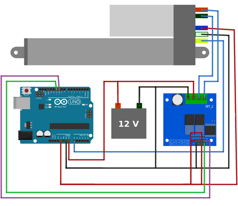
Wiring Connections Explained
Power Connections: Connect your 12V power supply to the motor driver's power input terminals. Ensure proper polarity – reversing voltage can damage the driver immediately. The Arduino should be powered separately through its USB connection or voltage regulator input, with a common ground established between Arduino, motor driver, and power supply.
Motor Driver to Actuator: The actuator's two main power wires connect to the motor driver's output terminals. These carry the high-current motor power and their polarity determines extension/retraction direction. If your actuator moves in the wrong direction during testing, simply swap these two connections.
Feedback Potentiometer Connections: The feedback actuator has three additional wires for the integrated potentiometer. Connect the potentiometer's power wire to Arduino's 5V pin, the ground wire to Arduino GND, and the signal (wiper) wire to an analog input pin (A0 in this example). These connections enable the Arduino to read position without affecting the motor power circuit.
Arduino to Motor Driver Control: Two Arduino digital pins connect to the motor driver's direction control inputs, and one PWM-capable pin connects to the enable input for speed control. These digital signals command the motor driver to extend, retract, or stop the actuator.
Safety Considerations
Never connect the actuator's motor power directly to Arduino pins – the current requirements (3-6A) far exceed what microcontroller pins can safely provide (40mA maximum). This is why the motor driver acts as an intermediary, using low-current Arduino signals to control high-current motor power switching. Additionally, ensure all connections are secure and insulated to prevent short circuits, which can damage both the Arduino and power supply.
Calibration Code: Automatic Range Detection
The first program performs an essential calibration sequence that determines the actual analog reading range of your specific actuator. This compensates for variations in gear ratios, potentiometer positioning, and manufacturing tolerances that affect the usable feedback range.
https://gist.github.com/Will-Firgelli/8c78092ca850aa8a50ae36842b97150f
How the Calibration Process Works
When the sketch starts, it commands the actuator to fully extend, recording the maximum analog reading, then fully retract, recording the minimum reading. These values are stored in variables and used to map subsequent analog readings to actual distance measurements in inches (or your preferred unit).
Line 16 of the code requires modification to match your actuator's stroke length. If you're using a 4" actuator instead of the default 6" setting, change this value accordingly. The stroke length parameter is crucial for accurate position calculation – a mismatch will cause all distance readings to be proportionally incorrect.
After calibration, the actuator continuously extends and retracts while streaming position data to the Serial Monitor. You'll see real-time updates showing the current extended length in inches, demonstrating how analog readings (0-1023) are converted to meaningful physical measurements through the map() and calibration functions.
Understanding Key Code Sections
The calibration sequence (lines 27-28) captures sensorMin and sensorMax values by reading the potentiometer at both stroke limits. These become reference points for the entire usable range of motion.
The map() function performs linear interpolation, converting analog readings to distance units. It takes the current sensor reading and proportionally scales it between 0 and the stroke length based on the calibrated minimum and maximum values.
The motor control logic uses digitalWrite() commands to control direction pins and analogWrite() on the enable pin to control speed through pulse-width modulation (PWM). This approach works with most standard H-bridge motor drivers designed for Arduino interfacing.
Implementing Position Control with External Setpoint
Reading position is useful, but most practical applications require commanding the actuator to move to specific positions. The second circuit and program demonstrate closed-loop position control using an external potentiometer as a user interface for setting desired positions.
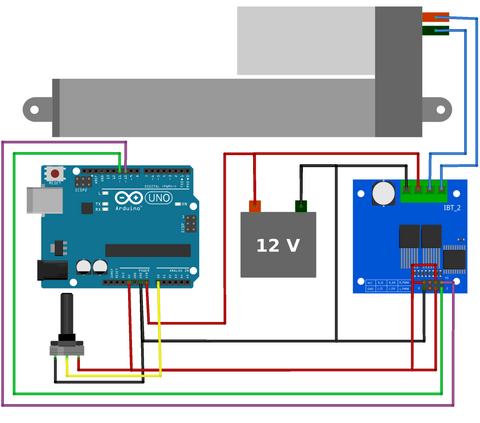
Enhanced Circuit Assembly
The wiring is nearly identical to the first example, with one critical addition: an external 10kΩ potentiometer connected to analog input A1. This potentiometer serves as a physical user interface – rotating it sets the desired actuator position. Connect the potentiometer's outer terminals to 5V and GND, with the center wiper terminal to A1.
This external potentiometer can be mounted in a control panel, enclosure, or simply left on a breadboard for testing. In production applications, you might replace this with a touchscreen interface, rotary encoder, or programmatic setpoint determined by sensor inputs or automation logic.
Position Control Code and Logic
https://gist.github.com/Will-Firgelli/41ec87433f0aaa1abc33e79168076b3b
This program continuously compares the external potentiometer setpoint (what position you want) with the actuator's current position (where it actually is) and drives the motor to minimize this error. When the actuator reaches the setpoint within an acceptable tolerance, the motor stops.
Understanding the Deadband Buffer Zone
Line 18 defines a critical parameter called the buffer or deadband. This variable (set to 5 in the example) creates a tolerance range around the setpoint where the actuator considers itself "close enough" and stops moving. Without this buffer, the system becomes unstable.
Why is this necessary? Analog readings from potentiometers naturally fluctuate by ±2-3 counts due to electrical noise, contact resistance variations, and ADC quantization. If the control logic demanded exact matching (buffer = 0), the actuator would violently oscillate around the setpoint, rapidly switching between extending and retracting. This oscillation wastes energy, generates heat, causes mechanical wear, and can damage the actuator over time.
Lines 36 and 39 implement the buffer logic by checking if the current position is within the acceptable range (setpoint ± buffer) before issuing movement commands. You can experiment with different buffer values – smaller values increase positioning precision but risk instability, while larger values improve stability but reduce accuracy.
Extending the Control Logic
This example uses proportional control – the motor runs at constant speed until reaching the setpoint. More sophisticated implementations might include:
- Velocity profiling: Slow down as the actuator approaches the setpoint for smoother arrival
- PID control: Implement proportional-integral-derivative control for faster response and better disturbance rejection
- Multi-point positioning: Store and recall multiple preset positions for automated sequences
- Speed control: Vary motor speed based on load conditions or application requirements
Troubleshooting Common Issues
Actuator Doesn't Move
First, verify your power supply is connected and providing 12V. Measure voltage at the motor driver's power input terminals with a multimeter. Check that motor driver control signals are reaching the appropriate pins by adding Serial.print() statements to output pin states. Confirm the motor driver is adequately rated for your actuator's current draw – an undersized driver may enter thermal protection mode.
Erratic Position Readings
Noisy or unstable position readings often result from poor grounding. Ensure all ground connections (Arduino, motor driver, power supply, potentiometer) share a common ground point. Long, unshielded wires can pick up electrical noise – keep feedback signal wires short and away from motor power wires. Add a small capacitor (0.1µF ceramic) between the potentiometer signal line and ground near the Arduino to filter high-frequency noise.
Incorrect Distance Measurements
Verify the stroke length parameter in line 16 matches your actuator's actual stroke. Double-check that calibration completes successfully – watch Serial Monitor output during the initial extension/retraction sequence. If sensorMin and sensorMax values seem incorrect, ensure the actuator reaches physical end-stops during calibration.
Actuator Moves in Wrong Direction
Simply swap the two motor power wires connected to the motor driver outputs. Direction is determined by polarity, and there's no universal standard for which wire should connect to which terminal. This is normal and doesn't indicate a wiring error.
Advanced Applications and Integration
Once you've mastered basic position reading and control, numerous advanced applications become possible. Feedback actuators excel in applications requiring precise, repeatable positioning without external sensors.
Multi-Actuator Synchronization
Control multiple actuators simultaneously for parallel motion platforms, adjustable tables, or robotic mechanisms. The Arduino can read position from multiple feedback actuators and coordinate their movement to maintain synchronization, compensating for manufacturing variations or uneven loading that would cause standard actuators to drift out of alignment.
Automated Positioning Systems
Integrate position control into larger automation systems for applications like adjustable standing desks, TV lifts, or camera positioning rigs. Store multiple preset positions in EEPROM and recall them via buttons, remote controls, or automated schedules.
Force Sensing Through Current Monitoring
By adding current sensing to the motor power circuit, you can detect when an actuator encounters resistance (obstruction, end-of-travel, or load changes). This enables safety features like obstacle detection or adaptive force control where the actuator responds to external forces.
Wireless Control Integration
Pair the Arduino with WiFi, Bluetooth, or RF modules to enable wireless position control. This is particularly valuable for applications where running wires is impractical, such as mobile robots or remote monitoring systems. The position feedback ensures accurate control even with potential communication latency or packet loss.
Selecting the Right Feedback Actuator for Your Project
FIRGELLI offers feedback actuators in various configurations, and choosing the appropriate model significantly impacts project success. Consider these factors:
Stroke Length: Select a stroke that provides adequate travel for your application with some margin. Common strokes range from 2" for compact applications to 12" or more for larger positioning systems. Longer strokes generally have lower maximum force ratings due to mechanical considerations.
Force Rating: Actuators are rated in pounds (lbs) or Newtons (N) of pushing/pulling force. Calculate your application's force requirements including the weight being moved, friction, and any external forces. Always include a safety factor – if calculations show 50 lbs needed, specify an actuator rated for 75-100 lbs.
Speed: Linear actuator speed is typically specified in inches per second (in/s) or millimeters per second (mm/s) at no load. Speed and force have an inverse relationship – higher force actuators generally move slower. Consider whether your application prioritizes speed or force.
Mounting Style: Different actuator series offer various mounting options. Standard clevis mounts work for many applications, while track actuators provide guided motion, and bullet actuators offer compact installation in space-constrained applications.
Environmental Factors: Consider operating temperature, humidity, and exposure to dust or moisture. Industrial actuators offer enhanced sealing and durability for demanding environments, while standard actuators work well in typical indoor applications.
Conclusion
Integrating potentiometric feedback with Arduino-based control transforms linear actuators from simple extension/retraction devices into sophisticated positioning systems capable of precise, repeatable motion control. The techniques demonstrated in this tutorial provide a foundation for countless automation, robotics, and motion control applications.
By understanding calibration requirements, implementing proper deadband logic, and carefully selecting components matched to your application requirements, you can create reliable position control systems that rival commercial solutions at a fraction of the cost. The modular nature of Arduino-based control also enables easy expansion and modification as project requirements evolve.
Whether you're building a prototype for proof-of-concept testing or developing a production automation system, the principles covered here – analog signal processing, closed-loop feedback control, and practical noise management – apply universally across motion control applications. Start with these basic circuits and gradually incorporate advanced features like multi-actuator coordination, wireless control, or integration with larger automation frameworks.
Frequently Asked Questions
Can I use this setup with 24V actuators instead of 12V?
Yes, but you must ensure your motor driver is rated for 24V operation. The Arduino and feedback potentiometer still operate at 5V, so those connections remain unchanged. Only the motor power circuit needs to handle the higher voltage. Select a motor driver specifically rated for your voltage and current requirements, and use an appropriately rated 24V power supply. The control logic and wiring remain identical – voltage differences only affect the power supply and motor driver specifications.
How often does the actuator need recalibration?
For most applications, a single calibration at startup is sufficient and remains valid until power is cycled. The calibration compensates for manufacturing tolerances and installation variations, which don't change during normal operation. However, if your application experiences temperature extremes, mechanical shock, or you replace the actuator, recalibration is recommended. Some implementations store calibration values in Arduino's EEPROM so they persist across power cycles, eliminating the need for startup calibration sequences.
What positioning accuracy can I expect with this system?
With Arduino's 10-bit ADC (1024 discrete steps) and proper calibration, positioning resolution depends on stroke length. A 6" actuator provides approximately 0.006" (0.15mm) theoretical resolution per ADC count. Practical accuracy is typically ±0.02-0.05" (0.5-1.3mm) due to mechanical backlash, potentiometer linearity, and electrical noise. The deadband buffer affects final positioning accuracy – a buffer of 5 counts on a 6" actuator represents approximately ±0.03" tolerance. For higher precision, consider actuators with hall-effect or optical encoders instead of potentiometric feedback.
Can I control multiple feedback actuators with one Arduino?
Absolutely. Each actuator requires one analog input pin for feedback and 2-3 digital pins for motor control (depending on your motor driver). An Arduino Uno has 6 analog inputs and 14 digital pins, allowing control of multiple actuators. For example, you could control two actuators using analog pins A0 and A1 for feedback, with separate motor drivers connected to different digital pin groups. For projects requiring many actuators, consider an Arduino Mega with 16 analog inputs and 54 digital pins, or implement multiplexing techniques to expand capacity.
How can I add limit switches or safety features to prevent over-extension?
While the feedback system provides position data, physical limit switches add redundant safety. Connect normally-closed limit switches in series with the motor driver's enable input, or monitor them via Arduino digital inputs and stop motor commands in software when triggered. Implement current sensing to detect mechanical resistance indicating obstructions or binding. In the code, add position limit checks that halt movement if the actuator approaches or exceeds expected travel range, even if calibration data suggests otherwise. For critical applications, combine multiple safety approaches – software limits, hardware limit switches, and current monitoring – to ensure protection against various failure modes.


