When designing motion control systems, engineers and DIY enthusiasts alike often focus on the pushing capacity of linear actuators—but what about pulling? This seemingly simple question has significant implications for application design, safety factors, and actuator selection. Whether you're building a TV lift, automated hatch, or industrial machinery, understanding the tensile (pulling) capabilities of your actuator is just as critical as knowing its compressive (pushing) force.
🎥 Video — Can Linear Actuators Pull?
The short answer is yes, linear actuators can pull, but the force capacity varies dramatically depending on the actuator type. Electric linear actuators maintain equal force in both directions, while pneumatic and hydraulic cylinders typically exhibit reduced pulling capacity compared to pushing. This fundamental difference stems from the underlying physics of how each technology generates force, and it's a factor that can make or break your design if not properly accounted for.
Understanding Push vs. Pull Forces in Linear Actuators
Before diving into specific actuator technologies, it's important to establish terminology. In the context of linear actuators, pushing force refers to the load capacity during extension—when the actuator rod moves outward from the cylinder body. Conversely, pulling force (also called tensile force or retraction force) describes the load capacity when the actuator retracts, drawing the rod back into the body.
For many applications, the distinction is academic—if your design only requires pushing (like lifting a hatch from below), you may never need to consider pulling capacity. However, numerous real-world scenarios demand reliable tensile force:
- Retracting a TV lift mechanism against friction and cable tension
- Closing vertically-oriented panels or doors where gravity assists extension but opposes retraction
- Operating automated blinds or shutters where the actuator must pull fabric or slats against wind resistance
- Industrial machinery that requires bidirectional force for clamping, pressing, or material handling
- Marine applications where actuators control rudders, trim tabs, or access hatches that face water resistance in both directions
In these scenarios, assuming equal push and pull capacity without verifying specifications can lead to underpowered systems, premature failure, or safety hazards. The force asymmetry in certain actuator types isn't a defect—it's a predictable characteristic of their mechanical design that must be incorporated into engineering calculations.
Hydraulic and Pneumatic Actuators: The Area Differential Challenge
Pneumatic and hydraulic cylinders are widely used in industrial settings for their high force-to-weight ratios and ability to handle harsh environments. However, these systems exhibit a fundamental mechanical limitation that affects their pulling capacity: the presence of the rod reduces the effective area during retraction.
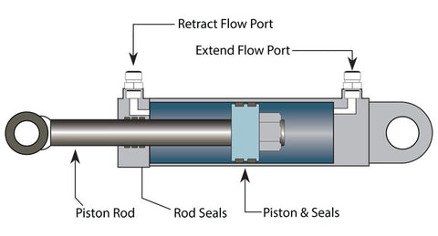
How Fluid Power Cylinders Work
Both pneumatic and hydraulic actuators operate on the same basic principle: pressurized fluid (air for pneumatic, incompressible oil for hydraulic) acts on a piston inside a cylinder, creating linear force. The relationship is elegantly simple:
Force = Pressure × Area
For a cylinder with a 2-inch bore operating at 100 PSI, the theoretical extension force would be approximately 314 pounds (π × 1² × 100). However, this calculation changes during retraction because the rod occupies space within the cylinder.
The Annular Area Reduction
When a fluid power cylinder extends, pressure acts on the full circular area of the piston (called the "cap end" or "blind end"). During retraction, however, pressure acts only on the annular area—the ring-shaped region between the cylinder bore and the rod. This reduced area directly translates to reduced force at the same operating pressure.
Consider a practical example: A hydraulic cylinder with a 2-inch bore and 1-inch rod has a full piston area of approximately 3.14 square inches. The annular area during retraction is only about 2.36 square inches (the piston area minus the rod cross-section). This represents a 25% reduction in effective area, resulting in 25% less pulling force at the same pressure.
The force reduction becomes more pronounced with larger rod diameters relative to bore size. While engineers can compensate by increasing system pressure during retraction, this approach has practical limits and may require more robust components, increasing cost and complexity.
Specialized Cylinder Configurations
Some hydraulic and pneumatic designs mitigate this limitation through alternative configurations:
- Double-rod cylinders: With rods extending from both ends of the cylinder, the effective area remains constant in both directions, equalizing push and pull forces
- Tandem cylinders: Two pistons on a common rod can be plumbed to provide enhanced force in one direction
- Differential pressure systems: Using different pressures for extension and retraction can balance forces, though this requires more sophisticated controls
Despite these solutions, standard single-rod pneumatic and hydraulic cylinders remain the most common and cost-effective option, making the push-pull force differential a factor that must be addressed in specification and sizing.
Electric Linear Actuators: Symmetric Force in Both Directions
Electric linear actuators represent a fundamentally different approach to linear motion, one that elegantly sidesteps the force asymmetry inherent in fluid power systems. For applications requiring equal bidirectional force, electric actuators offer significant advantages.
Electric Actuator Operating Principle
The typical rod-style electric linear actuator converts electrical energy to linear motion through a mechanical power transmission system. A DC or AC motor generates rotational motion, which passes through a gearbox for torque multiplication, then drives a lead screw or ball screw. A nut threaded onto the screw translates the rotation into linear movement, pushing or pulling the actuator rod.
This mechanical arrangement is fundamentally reversible. The motor can rotate equally well in clockwise or counter-clockwise directions, the gearbox transmits torque symmetrically regardless of direction, and the screw mechanism converts rotation to linear motion with identical efficiency whether threading in or out. The result: electric linear actuators provide equal force capacity in both extension and retraction.
Force Generation Factors
The maximum force an electric actuator can generate depends on three primary factors:
Motor size and power: Larger motors with higher wattage ratings provide more torque, directly increasing available force. A micro linear actuator might use a motor producing just a few watts, while industrial actuators can employ motors delivering hundreds of watts for forces exceeding 2,000 pounds.
Gearbox ratio: The gear reduction ratio multiplies motor torque at the expense of speed. Higher ratios produce more force but slower motion. This is why force and speed are inversely related in electric actuator specifications—a 1000-pound actuator might move at 0.5 inches per second, while a 100-pound version of the same actuator family might achieve 2 inches per second.
Lead screw pitch: The thread pitch (distance between threads) affects the mechanical advantage of the screw mechanism. Finer pitches provide more force but slower travel, while coarser pitches favor speed over force. Ball screws, with their reduced friction, can achieve higher efficiency than traditional lead screws, translating more motor power into useful force.
Critically, none of these factors change based on direction of travel. A 500-pound electric actuator will deliver 500 pounds pushing and 500 pounds pulling, assuming proper mounting brackets are used to handle tensile loads.
Types of Electric Actuators
While rod-style actuators are most common, several electric actuator configurations maintain equal bidirectional force:
Track actuators use a moving carriage on an external rail rather than a telescoping rod, ideal for applications requiring side-loading resistance. The electric motor drives the carriage along the track with equal force in both directions.
Bullet actuators feature a compact cylindrical design where the motor housing moves while the screw remains stationary (or vice versa). This configuration is particularly useful in space-constrained applications and maintains symmetric force characteristics.
Column lifts designed for height-adjustable applications like standing desks use nested tubes that telescope vertically. While these primarily work against gravity (pulling down is assisted by the load), the electric drive system provides controlled force in both raising and lowering.
Feedback actuators incorporate position sensors (potentiometers, Hall effect sensors, or encoders) that enable precise control and synchronization. The feedback mechanism doesn't affect force capacity—these actuators maintain equal push and pull forces while providing position data for advanced control schemes.
Application Considerations: When Pulling Forces Matter
Understanding the theoretical differences between actuator types is essential, but practical application design requires considering several additional factors that affect pulling performance.
Mounting and Mechanical Considerations
When an actuator pulls, it creates tensile stress not just in the actuator rod but throughout the mounting system. The mounting brackets must be designed to handle this load direction. Rod-end bearings, clevis mounts, and pivot points experience different stress patterns in tension versus compression.
For applications where the actuator must pivot during travel, proper mounting becomes even more critical. A clevis mount provides a single-axis pivot point that must resist side-loading. When pulling through an angle, calculate the actual tensile force on the rod—it may exceed the linear load due to geometric factors.
Column buckling is often discussed for pushing applications, but pulling eliminates this concern. A slender actuator rod that would buckle under 200 pounds of compressive load might safely handle 500 pounds in tension, limited only by the actuator's mechanical design and motor capacity. This characteristic sometimes allows using a longer-stroke actuator in pulling applications than would be advisable for pushing.
Friction and Dynamic Loads
Real-world applications rarely involve pure static loads. Friction in slides, guides, and pivot points can significantly increase the force required for motion. When retracting a drawer slide mechanism or pulling a panel along slide rails, friction may account for 20-50% of the total load depending on the bearing surfaces and lubrication.
Additionally, consider acceleration forces. If your application requires rapid retraction, the actuator must overcome both the static load and the inertial resistance of accelerating that mass. This is particularly relevant in high-speed automation where cycle times matter. Using a control box with adjustable speed settings can help balance force requirements against motion speed.
Safety Factors and Reliability
Standard engineering practice calls for applying safety factors to account for real-world variability, wear over time, and unexpected loading conditions. A common approach is to size actuators for 150-200% of the calculated maximum load. When pulling capacity differs from pushing capacity (as in fluid power cylinders), ensure your safety factor applies to the pulling direction if that's the critical load case.
For life-critical applications or those involving personnel safety, consult relevant safety standards and consider even more conservative factors. An automotive hatch actuator that must reliably retract a closure panel thousands of times over years of service requires careful attention to pulling force capacity, mounting integrity, and environmental factors like temperature and contamination.
Selecting the Right Actuator for Bidirectional Applications
When your application requires substantial pulling force, the actuator selection process should prioritize this requirement from the start rather than treating it as an afterthought.
Specification Review
Always review the complete actuator specifications, paying particular attention to how push and pull forces are listed. Reputable manufacturers clearly state if force ratings differ by direction. For electric linear actuators, you'll typically see a single force rating that applies to both directions. For hydraulic and pneumatic units, look for separate "extend force" and "retract force" specifications.
Don't assume ratings are symmetrical if not explicitly stated. When specifications are unclear, contact the manufacturer's technical support for clarification. For custom or critical applications, request test data demonstrating performance in your specific load configuration.
Electric vs. Fluid Power Trade-offs
While electric actuators offer equal bidirectional force, the choice between electric and fluid power involves numerous other factors:
Force capacity: Hydraulic cylinders can achieve extremely high forces in compact packages—10,000+ pounds in a reasonably sized unit. Electric actuators typically max out around 2,000-6,000 pounds for standard industrial units, though specialized designs can reach higher.
Speed: Pneumatic cylinders can be very fast, while hydraulic systems offer moderate to high speeds. Electric actuators are generally slower, with typical speeds ranging from 0.25 to 3 inches per second depending on force requirements and duty cycle.
Control precision: Electric actuators, especially feedback actuators, offer superior position control and can easily stop at any point in the stroke. Fluid power systems can achieve good control but require proportional valves and more sophisticated hydraulics/pneumatics.
Environment: Hydraulic systems handle extreme temperatures, shock, vibration, and dirty environments well. Electric actuators may require environmental protection in harsh conditions but offer cleaner operation with no risk of fluid leaks.
Infrastructure: Electric actuators only need appropriate power supplies (typically 12V or 24V DC, sometimes 110V/220V AC). Fluid power requires compressed air lines or hydraulic power units with pumps, reservoirs, and plumbing.
Cost: For lower force applications (under 500 pounds), electric actuators are often more cost-effective when considering the total system cost including controls, installation, and maintenance. At higher forces, hydraulics may offer better value despite the push-pull force differential.
Sizing for Pulling Applications
If your application requires pulling and you've chosen a technology with asymmetric force (pneumatic or hydraulic), follow this sizing approach:
- Calculate the maximum pulling force required, including friction, dynamic loads, and appropriate safety factors
- Review the retraction force specification for candidate actuators—this is your limiting factor, not the extension force
- Select an actuator with retraction force exceeding your calculated requirement
- Verify that the extension force (which will be higher) doesn't create problems for your application—excessive force could damage components or create safety issues
- Consider whether adjustable pressure/flow controls could help balance performance and force in both directions
For electric actuators, the process is simpler since push and pull forces are equal. Size based on the maximum load in either direction, apply safety factors, and select an actuator that meets or exceeds your requirements while fitting within stroke length, speed, and duty cycle parameters.
Practical Installation Tips for Pulling Applications
Even with the right actuator selected, proper installation ensures reliable pulling performance over the system's lifetime.
Alignment and Mounting
Misalignment creates side-loading that increases friction and can cause premature wear or binding, especially problematic in pulling applications where the rod is under tension. Use proper mounting brackets at both the actuator body and rod end that allow appropriate degrees of freedom while constraining unwanted motion.
For applications with changing geometry during travel (like a hatch that rotates as it opens), clevis mounts or rod-end bearings accommodate the angular changes. Ensure these pivot points are properly lubricated and sized for the tensile loads they'll experience.
When using track actuators, verify that the track is straight and properly supported along its length. Any bow or twist in the track will increase friction and reduce effective pulling force. Use a straightedge during installation and shim as necessary to achieve proper alignment.
Electrical Considerations
For electric actuators, ensure adequate power delivery for the full load. Voltage drop in undersized wiring can reduce available motor power, particularly problematic under heavy pulling loads where the motor draws maximum current. Use appropriately sized wire gauges based on the actuator's current draw and cable length.
If using multiple actuators in a synchronized application (like a dual-actuator TV lift), consider feedback actuators with a control box that can actively synchronize position. Without feedback, slight differences in friction or loading can cause the actuators to drift out of sync, creating side-loading and reducing effective pulling force.
Testing and Commissioning
Before putting a pulling application into service, conduct thorough testing under realistic load conditions. Verify that the actuator can complete full extend/retract cycles reliably and monitor for any signs of binding, unusual noise, or excessive heat buildup in the actuator or motor.
For critical applications, consider installing limit switches or using feedback actuators to prevent over-travel that could damage mechanical stops or create dangerous conditions. A control box with integrated protection features can also help prevent damage from stalls or overload conditions.
Conclusion
The ability of linear actuators to pull is not a simple yes-or-no question but rather depends fundamentally on the actuator technology and proper system design. Electric linear actuators provide symmetric force in both directions, making them ideal for applications where equal push and pull capacity is required. Pneumatic and hydraulic cylinders, while capable of pulling, typically exhibit reduced retraction force due to the annular area effect—a predictable characteristic that must be accounted for during sizing and specification.
Successful implementation of pulling applications requires attention to mounting details, realistic load calculations including friction and dynamic effects, and appropriate safety factors. Whether you're designing an automated panel system, TV lift mechanism, or industrial automation, understanding the pulling capabilities and limitations of your chosen actuator technology ensures reliable, safe operation over the system's service life.
Frequently Asked Questions
Do all linear actuators have the same pushing and pulling force?
No. Electric linear actuators provide equal force in both directions because their mechanical drive system (motor, gearbox, and lead screw) operates symmetrically regardless of rotation direction. However, pneumatic and hydraulic cylinders typically have reduced pulling force compared to pushing force due to the rod occupying space within the cylinder during retraction, reducing the effective piston area. Always check the manufacturer's specifications for both extend and retract force ratings.
Why do hydraulic and pneumatic cylinders pull with less force than they push?
In standard single-rod hydraulic and pneumatic cylinders, the force generated equals pressure multiplied by the effective piston area. During extension, pressure acts on the full circular area of the piston. During retraction, pressure acts only on the annular area—the ring-shaped region between the cylinder bore and the rod. Since the rod reduces the effective area, less force is generated at the same pressure. The reduction is proportional to the rod diameter; larger rods create greater force differential between pushing and pulling.
What safety factor should I use when sizing an actuator for pulling applications?
A standard engineering safety factor of 1.5 to 2.0 (150-200% of calculated maximum load) is typical for most actuator applications. This accounts for friction, dynamic loads, wear over time, and unexpected conditions. For life-critical applications or those involving personnel safety, use more conservative factors and consult relevant safety standards. When using pneumatic or hydraulic cylinders with reduced pulling force, ensure your safety factor applies to the retraction force specification, not the higher extension force rating.
Can I use a linear actuator to both push and pull in the same application?
Yes, linear actuators are designed for bidirectional operation and can both push and pull within the same application. Electric actuators are particularly well-suited for this since they provide equal force in both directions. If using fluid power cylinders, size the actuator based on the retraction (pulling) force requirement, which will be the limiting factor. Ensure your mounting brackets and mechanical connections can handle both tensile and compressive loads safely.
What type of actuator is best for applications requiring strong pulling force?
For applications where pulling force is a primary requirement, electric linear actuators offer the advantage of equal push and pull capacity, simplifying sizing and specification. They're available in force ratings from a few pounds in micro linear actuators to over 2,000 pounds in industrial actuators. For extremely high forces (several thousand pounds or more), hydraulic cylinders may still be the best choice despite the push-pull differential, but they'll need to be sized based on the reduced retraction force. Double-rod hydraulic cylinders eliminate the force differential but are more expensive and complex.
How do I prevent side-loading when an actuator is pulling at an angle?
Use appropriate mounting hardware that accommodates angular changes during travel. Clevis mounts and rod-end bearings allow single-axis rotation at the connection points, preventing side-loading as the geometry changes. For applications requiring multi-axis flexibility, spherical bearings can accommodate compound angles. Track actuators are particularly resistant to side-loading since the carriage is supported along the entire length of the rail. Proper alignment during installation is also critical—use precision measuring tools to ensure the actuator path is straight and properly positioned relative to the load.


