Understanding Electric Linear Actuator Styles: A Comprehensive Guide
When transitioning from hydraulic or pneumatic systems to electric actuation, one of the most critical decisions you'll face is selecting the right actuator style for your application. Unlike their hydraulic and pneumatic counterparts that require compressors, pumps, hoses, and regular maintenance, electric actuators offer a cleaner, more precise solution with minimal upkeep. However, the versatility of electric actuation comes with choices—specifically, six distinct actuator styles, each engineered for different mechanical requirements and installation constraints.
The internal architecture of an linear actuator fundamentally determines its performance characteristics: noise levels, force capability, physical dimensions, and mounting flexibility. Whether you're designing a medical device requiring whisper-quiet operation, an industrial application demanding high side-load resistance, or a compact mechanism with severe space limitations, understanding these architectural differences will guide you to the optimal solution. This guide examines each actuator style in detail, explaining the engineering trade-offs and ideal use cases for parallel drive, right-angle, in-line, rotary, track, and telescopic column designs.
Before diving into specific styles, it's worth noting that all electric linear actuators share common advantages: precise position control, programmable motion profiles, elimination of fluid leaks, and integration with modern control systems including Arduino and similar platforms. The question isn't whether electric actuation is right for your project—it's which architecture best serves your specific requirements.
Parallel Drive Actuators: Versatile Force and Speed Configuration
Parallel drive actuators represent one of the most common and versatile architectural approaches in electric linear actuation. In this design, the motor is mounted parallel to the main leadscrew, with power transmitted through a spur gear or spiral gear mechanism. This configuration offers significant engineering advantages when it comes to customization and force-speed optimization.
The defining characteristic of parallel drive architecture is its exceptional flexibility in gear ratio selection. Because the motor and leadscrew run parallel to each other, engineers can easily interchange gear sets without redesigning the housing or fundamental structure. This means a single actuator family can offer force ratings from 200 lbs to over 2,000 lbs simply by changing the internal gearing—the external dimensions and mounting brackets remain identical. For manufacturers and designers, this translates to simplified inventory and easier specification changes during development.

Force capacity in parallel drive actuators typically ranges from 150 lbs in compact models up to 2,200 lbs in heavy-duty variants. Stroke lengths are equally versatile, with options from 1 inch to 36 inches depending on the model series. Speed varies inversely with force—a 200 lb actuator might achieve 2 inches per second, while a 2,000 lb unit in the same family operates closer to 0.3 inches per second.

Noise Characteristics and Mitigation
The primary trade-off with parallel drive actuators lies in acoustic performance. Spur gears, while efficient and cost-effective, generate more audible noise than other drive mechanisms—typically 55-65 dB at one meter under load. This occurs because spur gear teeth engage with a percussive action rather than a gradual rolling contact. For industrial applications, agricultural equipment, or outdoor installations, this noise level is rarely problematic. However, for residential furniture, medical equipment, or office automation, the acoustic signature may be noticeable.
When noise is a concern but the versatility of parallel drive architecture is desired, specifying spiral or helical gears can reduce operational noise by 10-15 dB. The helical tooth geometry creates a more gradual engagement, distributing forces over multiple teeth simultaneously. The downside is increased manufacturing complexity and slightly higher cost.
Ideal Applications for Parallel Drive
Parallel drive actuators excel in applications requiring:
- Multiple force options within the same equipment line
- Industrial automation where noise is not a primary concern
- Agricultural and outdoor equipment
- Heavy-duty applications requiring forces above 1,000 lbs
- Situations where the parallel motor orientation simplifies mounting
- Projects requiring industrial actuators with proven reliability under continuous duty cycles
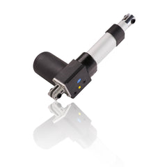
Right-Angle (L-Drive) Actuators: Quiet Operation and Self-Locking Capability
Right-angle or L-drive actuators take a fundamentally different approach to power transmission. The motor is positioned perpendicular to the leadscrew, requiring a 90-degree power transfer achieved through a worm gear mechanism. This architectural choice brings distinct advantages in noise reduction and back-drive resistance, though with some limitations in gear ratio flexibility.
The worm gear drive system is inherently quieter than spur gear arrangements. Instead of the percussive tooth engagement of spur gears, the worm threads engage with a sliding action across the worm wheel teeth. This creates a significantly reduced acoustic signature—typically 45-50 dB under load, which is quiet enough for residential and office environments. In fact, with a right-angle actuator, the motor itself often becomes the primary noise source rather than the gear mechanism.
Self-Locking Behavior and Safety
One of the most valuable features of worm gear drives is their inherent self-locking characteristic. The geometry of worm gears creates a mechanical condition where the gear can easily drive the worm wheel, but the worm wheel cannot back-drive the worm. In practical terms, this means a right-angle actuator will hold its position under load without requiring continuous power—the mechanical friction in the worm gear prevents back-driving.

This property is particularly valuable in vertical lifting applications or any situation where actuator back-driving poses a safety risk. A TV lift mechanism, for example, benefits from self-locking behavior—if power is lost, the TV remains in position rather than dropping. Similarly, in medical bed positioning or adjustable workstations, self-locking prevents unintended movement.
Gear Ratio Constraints
The perpendicular motor orientation does introduce some limitations. Worm gear ratios are constrained by the physical geometry of the worm threads—you cannot achieve the same wide range of ratios available in parallel drive systems. This means right-angle actuator families typically offer fewer force/speed combinations. You might find three or four distinct force ratings in a right-angle product line versus six or eight in a comparable parallel drive family.
Optimal Applications for Right-Angle Actuators
- Residential furniture and home automation where quiet operation is essential
- Medical equipment and hospital beds
- Office ergonomic equipment including standing desks
- Vertical lifting applications requiring self-locking for safety
- Installations where the perpendicular motor orientation simplifies packaging
- Applications where the load must be held without continuous power consumption
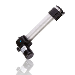
In-Line Actuators: Compact Diameter and Aesthetic Integration
In-line actuators represent the most spatially efficient design when diameter constraints are paramount. With the motor, gearbox, and leadscrew all positioned on a common centerline, these actuators achieve a symmetrical, cylindrical form factor that's ideal for tight radial spaces and applications where visual aesthetics matter.
The coaxial arrangement creates a clean, streamlined appearance that integrates naturally into modern product design. When an actuator will be visible in the final application—such as in adjustable lighting fixtures, retail displays, or medical devices—the uniform cylindrical profile of an in-line design often proves more visually acceptable than the asymmetrical bulk of parallel or right-angle configurations.

Length vs. Diameter Trade-offs
The primary compromise with in-line architecture is axial length. Because the motor and gearbox must be positioned behind the leadscrew rather than beside it, in-line actuators are inherently longer than equivalent parallel or right-angle units. A bullet actuator with a 4-inch stroke might have a retracted length of 12-14 inches, whereas a parallel drive actuator with the same stroke could achieve a 9-10 inch retracted length.

This length penalty becomes particularly relevant in applications with limited axial clearance. Before specifying an in-line actuator, carefully verify that your installation envelope can accommodate both the retracted length and the additional stroke extension. The benefit is a dramatically reduced diameter—in-line actuators are available in diameters as small as 8mm for micro actuator applications, where parallel drive designs would require at least 25-30mm.

Performance Characteristics
In-line actuators typically employ planetary gear reduction, which offers excellent efficiency and relatively quiet operation. Noise levels fall between parallel drive and right-angle designs—approximately 50-55 dB under load. Force capacity ranges from just a few pounds in miniature micro linear actuators up to 300-400 lbs in larger industrial variants. The coaxial design naturally handles pure axial loads very well but offers minimal resistance to side loading or moment forces.
Best Applications for In-Line Actuators
- Medical devices and laboratory equipment where diameter is constrained
- Automotive and aerospace applications with tight radial packaging
- Consumer products and electronics where aesthetics matter
- Robotic systems requiring linear motion along existing structural members
- Situations with adequate axial space but severely limited radial clearance
- Applications requiring the smallest possible micro linear actuator form factor
Rotary Actuators: Continuous Motion and Torque Application
While linear actuators dominate most motion control discussions, rotary actuators fill a distinct niche for applications requiring continuous or angular positioning rather than point-to-point linear travel. Fundamentally, a rotary actuator is a geared motor optimized for position control and torque delivery rather than speed—it's what you'd have if you removed the leadscrew and nut from a linear actuator.
The output shaft of a rotary actuator rotates continuously in either direction without physical stops (unless specifically added by the user). This makes them ideal for applications like valve control, antenna positioning, adjustable louvers, camera pan mechanisms, or any situation where you need controlled rotational motion rather than linear extension.

Understanding Torque and Speed Relationships
Rotary actuators are specified by torque (typically in Newton-meters or inch-pounds) and rotational speed (RPM) rather than the force and linear speed used for linear actuators. The fundamental trade-off remains the same: torque and speed are inversely proportional through gear ratio selection. A high-torque rotary actuator might deliver 50 Nm at 10 RPM, while a high-speed variant produces 5 Nm at 100 RPM.
This relationship stems from the physics of gear reduction. Each stage of reduction multiplies torque while proportionally reducing speed. When selecting a rotary actuator, you must determine which parameter is more critical for your application—the force required to move the load or the speed at which it must move—because optimizing one necessarily compromises the other.
Position Control and Feedback
Unlike linear actuators where internal limit switches naturally define travel endpoints, rotary actuators require external sensors or control logic to establish positional boundaries. Many applications integrate potentiometers, encoders, or hall-effect sensors to provide position feedback. When precise angular positioning is required, specifying feedback actuators with integrated position sensing simplifies system design and improves accuracy.
Rotary Actuator Applications
- Valve actuation and flow control
- Solar panel tracking systems
- Antenna and satellite dish positioning
- Adjustable louvers and vent control
- Camera and sensor pan/tilt mechanisms
- Robotic joints requiring continuous rotation
- Conveyor direction switching
Track Actuators: Distributed Load and Flexible Mounting
Track actuators, also called slide actuators or rail actuators, abandon the traditional rod-and-housing design entirely. Instead of a telescoping rod extending from a cylindrical body, track actuators use a carriage (or multiple carriages) that travels along an exposed rail. This architectural change brings significant advantages in load distribution, mounting flexibility, and stroke-to-length ratio.
The rail itself forms the structural member, with the drive mechanism—typically a lead screw or belt drive—running along its length. One or more carriages ride on precision bearings or rollers, translating rotational motor input into smooth linear travel. This design excels in applications where the load must be supported along its length rather than at a single point.
Mounting and Load Distribution Advantages
Track actuators offer exceptional mounting versatility. The carriage typically includes multiple threaded mounting points on multiple faces, allowing attachment from the top, sides, or even bottom. Need to mount a wide panel or heavy component? Add a second or third carriage on the same rail to distribute the load and eliminate deflection concerns.

The exposed rail design also simplifies integration into existing structures. Rather than calculating precise mounting points for both ends of a rod actuator, you simply bolt the rail to a surface and attach your moving component to the carriage. This proves particularly valuable in retrofit situations or when design iterations require mounting changes—adjusting carriage position on a track actuator is far simpler than repositioning fixed actuator mounts.
Stroke Length Efficiency
Track actuators achieve excellent stroke-to-length ratios because there's no need to house a retracted rod inside a body. The overall length equals approximately the stroke plus the carriage length plus minimal end buffer. A track actuator with 500mm stroke might be only 600mm long overall, whereas a rod actuator with equivalent stroke could require 800-900mm to accommodate the retracted rod.
Ideal Track Actuator Applications
- Massage chair mechanisms requiring smooth, quiet linear motion
- Industrial assembly lines and material handling
- Precision positioning tables and CNC applications
- Camera dollies and video production equipment
- Wide panels or doors requiring distributed support
- Applications where mounting points need adjustment during development
- Clean room equipment where exposed rods would collect contaminants
Electric Lifting Column Actuators: Telescopic Extension and Side-Load Capability
Electric column lifts solve a fundamental challenge in linear actuation: achieving long stroke lengths while maintaining compact retracted dimensions. Through telescopic multi-stage design—typically two to four nested sections—column lifts can extend to three or even four times their collapsed height. A 600mm closed-length column might extend to 1,800mm, providing exceptional stroke efficiency impossible with single-stage designs.
The telescopic architecture creates a progressively larger diameter structure as sections nest together, resulting in substantially higher rigidity than a rod actuator of equivalent force rating. This increased structural capacity allows column lifts to handle significant side loads and moment forces—critical for applications like standing desks where the actuator must support a large platform rather than push a pure axial load.

Side-Load and Moment Resistance
Most traditional rod-style linear actuators perform poorly under side loading—applying force perpendicular to the rod axis causes premature bearing wear and potential binding. Manufacturers typically specify maximum side loads of 5-10% of rated axial force. Column lifts, by contrast, can handle side loads of 50% or more of their vertical capacity, with moment ratings measured in hundreds of Newton-meters.
This side-load capability stems from the multi-stage construction and larger bearing surfaces. Each telescopic section rides on multiple bearing points with substantial separation distance, creating high moment resistance. For a height-adjustable desk with 1,200mm width, the column at one corner must resist the cantilever moment from the opposite corner's load—a task impossible for standard actuators but well within column lift capabilities.
Multi-Column Synchronization
Many applications require multiple column lifts working in coordinated motion. Height-adjustable desks typically use two or four columns, while large TV lift mechanisms might employ two. Proper synchronization ensures all columns extend and retract at identical rates, preventing binding and uneven loading.
Synchronization is achieved through dedicated control electronics that monitor position feedback from each column and adjust individual motor speeds to maintain alignment. Quality control boxes include synchronization algorithms as standard features, automatically compensating for slight variations in mechanical efficiency or load distribution across multiple columns.
Column Lift Applications
- Height-adjustable sit-stand desks and workstations
- Medical examination tables and hospital beds
- Podium and presentation platform lifts
- Kitchen appliance lifts for mixers and heavy equipment
- Large-screen TV lifts from cabinets and consoles
- Adjustable height assembly workstations
- Wheelchair lifts and accessibility equipment
- Any vertical lifting application requiring long stroke with compact retracted height
Key Selection Criteria: Matching Actuator Style to Application
Selecting the optimal actuator style requires balancing multiple competing factors: force requirements, space constraints, noise tolerance, mounting configuration, and budget. This section provides a systematic approach to narrowing your options based on application-specific priorities.
Force and Speed Requirements
Begin with fundamental performance parameters. Calculate the maximum force required to move your load, including friction, gravity (for vertical applications), and any resistance forces. Add a 25-30% safety margin to account for mechanical inefficiency and aging. If your calculated requirement is 150 lbs, specify an actuator rated for at least 200 lbs.
Speed requirements interact with force through gear ratios. If your application demands both high force and high speed, you may need a larger motor or multiple actuators rather than attempting to optimize a single unit. Most actuator families offer multiple force/speed combinations—identify which parameter is more critical for your application and prioritize accordingly.
Physical Space and Mounting
Measure your available installation envelope carefully, accounting for both retracted length and full extension. Consider:
- Axial length: In-line and track actuators require more axial space than parallel or right-angle designs
- Radial diameter: In-line actuators offer the smallest diameter for tight radial spaces
- Motor protrusion: Parallel drive actuators extend significantly to one side; right-angle designs project perpendicular to the stroke axis
- Mounting point accessibility: Can you access both ends for mounting, or does one end require a floating clevis?
Acoustic Requirements
If your application operates in noise-sensitive environments—residential, office, medical—prioritize right-angle or in-line designs over parallel drive configurations. Request specific noise specifications from manufacturers; differences of 10 dB represent a perceived doubling of loudness.
Environmental Considerations
Operating environment significantly impacts actuator selection. Consider IP ratings for dust and moisture resistance—outdoor applications or washdown environments require IP65 or higher protection. Temperature extremes affect motor performance and lubricant viscosity; verify that your chosen actuator is rated for ambient conditions. For corrosive environments, stainless steel construction or protective coatings may be necessary.
Control and Feedback Requirements
How will you control actuator position? Simple limit-switch control works for basic extend/retract applications, but precise positioning requires feedback actuators with integrated potentiometers or hall-effect sensors. If you're integrating with programmable controllers or Arduino systems, verify that appropriate control boxes and interfaces are available.
Making the Right Choice for Your Application
Electric linear actuator selection ultimately comes down to understanding the engineering trade-offs inherent in each architectural style. Parallel drive actuators offer maximum force range and versatility at the cost of higher noise. Right-angle designs provide quiet, self-locking operation within a more limited force selection. In-line actuators achieve minimal diameter but require extended axial length. Track actuators excel at distributed loads and mounting flexibility. Rotary actuators address angular positioning needs. And column lifts solve the challenge of long-stroke vertical lifting with side-load resistance.
No single style is universally superior—each represents an optimized solution for specific application requirements. By systematically evaluating your needs for force, speed, space, noise, and environmental factors, you can confidently narrow the field to the actuator style that best serves your project. When specification questions arise, detailed technical documentation and application engineering support can help refine your selection and ensure successful integration.
Frequently Asked Questions
What's the main difference between parallel drive and right-angle actuators?
The fundamental difference lies in motor orientation and gear type. Parallel drive actuators mount the motor parallel to the leadscrew and use spur or spiral gears, offering greater force range flexibility but higher noise levels (55-65 dB). Right-angle actuators position the motor perpendicular to the leadscrew and employ worm gear drives, resulting in quieter operation (45-50 dB) and self-locking behavior, but with fewer gear ratio options. Choose parallel drive for industrial applications prioritizing force versatility, and right-angle for noise-sensitive environments like offices or medical settings where quiet operation and self-locking are valuable.
Why are in-line actuators longer than other styles?
In-line actuators must accommodate the motor and gearbox directly behind the leadscrew on the same centerline, rather than positioning them beside or perpendicular to it. This coaxial arrangement increases retracted length by 30-50% compared to parallel drive designs with equivalent stroke. The trade-off is a dramatically reduced diameter—often 40-60% smaller—making in-line actuators ideal when radial space is severely constrained but axial length is available. Applications in tight-diameter tubes or through narrow openings benefit from this design despite the length penalty.
When should I choose a track actuator over a traditional rod actuator?
Track actuators excel when you need distributed load support, flexible mounting positions, or have long stroke requirements with limited overall length. Choose a track actuator when: the load is wide or heavy enough to require multiple attachment points, mounting locations may need adjustment during development or installation, stroke-to-length ratio is critical (tracks offer nearly 1:1 versus 1:1.5-1:2 for rod actuators), or when the mechanism will be visible and the exposed rail aesthetic is preferable to a protruding rod. Track actuators also handle side loads better than single-point rod actuator mounts.
How much weight can electric lifting columns support?
Individual column lift capacity typically ranges from 200 lbs to 1,000 lbs per column depending on model and stage count. However, practical system capacity depends on multiple factors: number of columns (desks typically use 2-4 columns), load distribution (centered loads versus eccentric mounting), extension height (capacity decreases at maximum extension), and dynamic versus static loading (moving loads require higher safety margins). For a height-adjustable desk application, four columns rated at 500 lbs each might safely support 1,500-1,800 lbs total system weight when properly synchronized and distributed. Always verify specifications with your actuator supplier based on your specific mounting configuration and load distribution.
Do I need feedback actuators for position control?
It depends on your positioning accuracy requirements. Basic extend/retract applications using internal limit switches don't require feedback actuators—the actuator simply runs until it hits the mechanical stop. However, if you need to position the actuator at intermediate points, repeat positioning to specific locations, coordinate multiple actuators precisely, or integrate with programmable controllers for automated sequences, feedback is essential. Potentiometer feedback provides analog position signals with resolution typically better than 1% of stroke, while hall-effect sensors offer greater durability and precision. For Arduino and microcontroller integration, feedback signals enable closed-loop position control and sophisticated motion profiles.


