Understanding Synchronized Motion in Linear Actuator Systems
One of the most frequent challenges engineers and DIY builders face when implementing linear actuators in their projects is achieving perfectly synchronized motion across multiple units. Whether you're automating a truck bed cover, designing a custom TV lift mechanism, building a hidden wine cellar trapdoor, or engineering a precision spoiler system, the expectation is simple: wire two actuators to the same power source, and they should move in perfect harmony. The reality, however, is considerably more complex.
This comprehensive guide addresses the fundamental question of why linear actuators don't naturally synchronize, explores the engineering principles behind DC motor behavior, and presents proven solutions ranging from plug-and-play control boxes to advanced microcontroller-based systems. Whether you're working with feedback actuators that include built-in positional sensing or standard units without encoders, understanding these principles will prevent equipment damage, project failures, and the frustration of actuators that drift out of sync under load.
The consequences of poor synchronization extend beyond mere inconvenience. Mismatched actuator speeds create uneven loads, mechanical binding, premature wear, and in extreme cases, structural damage to the application or motor burnout. This tutorial provides both the theoretical foundation and practical implementation strategies to ensure your multi-actuator systems operate reliably and safely.
Why DC Linear Actuators Don't Naturally Synchronize
The assumption that two identical actuators wired to the same power supply will move at identical speeds is understandable but fundamentally incorrect. This is not a design flaw in FIRGELLI products or any other manufacturer's actuators—it's an inherent characteristic of all DC motors governed by electromagnetic principles and real-world manufacturing constraints.
Manufacturing Tolerances and Component Variations
Even with modern precision manufacturing, microscopic variations exist between individual motors. These include slight differences in armature winding resistance, magnetic field strength variations in permanent magnets, commutator segment spacing, and brush contact resistance. While these variations might measure in fractions of a percent, they directly impact motor speed characteristics. Two motors receiving identical voltage will draw slightly different currents and produce marginally different torque outputs.
Load Distribution and Mechanical Resistance
In practical applications, achieving perfectly balanced loads across multiple actuators is nearly impossible. Consider a truck bed cover supported by two actuators: even slight differences in mounting bracket alignment, hinge friction, or weight distribution create asymmetric loading. The actuator experiencing higher resistance will move slower, while the less-loaded unit advances faster. This speed differential compounds over the stroke length, potentially causing binding or structural stress.
Friction Variations and Mechanical Wear
Internal components like bushings, bearings, lead screws, and seals all contribute friction that varies between units. Manufacturing tolerances in bushing diameter, bearing preload, and lubrication distribution mean no two actuators have identical internal resistance. Furthermore, mechanical wear patterns develop differently based on operating hours, load history, and environmental conditions. An actuator that has operated for 1,000 cycles will have different friction characteristics than a brand-new unit, even if they started identically.
Realistic Speed Variation Expectations
Under typical operating conditions, expecting a 5-10% speed difference between nominally identical DC motors or linear actuators without feedback control is realistic and normal. Over a 12-inch stroke, this translates to one actuator potentially finishing more than an inch ahead of its partner. In applications with tight tolerances or rigid mechanical coupling, this differential can cause serious problems including motor stall, mechanical binding, or component failure.
Achieving True Synchronization with Feedback Actuators
The most reliable approach to synchronized motion employs closed-loop feedback control using actuators with built-in positional encoders. FIRGELLI's feedback actuators, including optical encoder models and Hall effect sensor-equipped bullet actuators, provide real-time position data that enables precise synchronization through continuous correction algorithms.
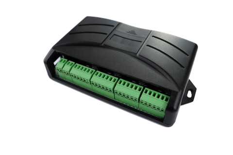
FA-SYNC-4 and FA-SYNC-2 Synchronous Control Boxes
The FA-SYNC series represents the most user-friendly and reliable solution for synchronized actuator control, requiring no programming expertise or custom circuit design. These dedicated control boxes support two to four actuators simultaneously and work exclusively with encoder-equipped models.
Compatible Actuator Models:
- Optical Series 200lb Force Actuator
- Optical Series 400lb Force Actuator
- 12V Bullet Series 36 Cal. Actuator
- 12V Bullet Series 50 Cal. Actuator
The system operates through an elegant auto-calibration process. Upon initial setup, the control box maps each actuator's full stroke range and establishes baseline performance characteristics. During operation, the microcontroller continuously monitors encoder signals from all connected actuators, comparing actual positions against commanded positions at millisecond intervals. When any actuator begins to deviate from the synchronized group, the controller automatically adjusts voltage to faster or slower units, maintaining positional accuracy typically within 1-2mm across the entire stroke.
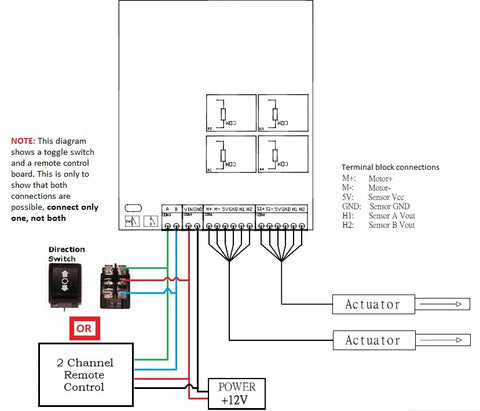
Installation is straightforward: connect actuators to the designated output ports, provide appropriate DC power (12V or 24V depending on actuator specifications), and connect control inputs (switches, relays, or external control signals). The auto-calibration sequence runs automatically on first power-up, after which the system is ready for operation. This plug-and-play approach makes synchronized control accessible to users without electronics or programming backgrounds while delivering industrial-grade performance.
Arduino-Based Control Using Interrupt Pins
For engineers and advanced makers who prefer custom control solutions, Arduino microcontrollers provide flexible platforms for implementing synchronized actuator control. This approach works with optical encoder and Hall effect sensor-equipped actuators, offering the advantage of complete customization at the cost of increased complexity.
The fundamental principle involves connecting encoder output signals to Arduino interrupt pins, which trigger immediately when signal transitions occur. By counting pulses and calculating their timing, the software determines real-time position and velocity for each actuator. Control algorithms—typically proportional-integral-derivative (PID) loops—then adjust motor drive signals to maintain synchronization.
Implementation considerations include:
- Interrupt service routines must execute quickly to avoid missing pulses during high-speed operation
- Motor driver circuits (H-bridges or motor controllers) must handle your actuators' current requirements, typically 3-6A continuous
- Pulse counting must account for direction (extend vs. retract) to maintain accurate position tracking
- Control loop timing must be fast enough to correct deviations before they become mechanically problematic
- Proper signal conditioning may be necessary to ensure clean, bounce-free encoder signals
This method requires solid understanding of microcontroller programming, interrupt handling, motor control theory, and debugging skills. FIRGELLI does not provide software support for custom Arduino implementations, as the virtually unlimited configuration possibilities make standardized support impractical. However, this approach offers maximum flexibility for integrating actuator control into larger automation systems or implementing specialized control algorithms.
Arduino Analog Pin Control with Feedback Rod Actuators
Feedback rod actuators incorporate internal potentiometers that provide continuous analog voltage output proportional to rod position. This simpler feedback mechanism lacks the precision of optical encoders but offers adequate performance for many applications while remaining easier to interface with microcontrollers.
The potentiometer typically outputs 0-5V or 0-3.3V (depending on supply voltage) across the actuator's full stroke. Arduino analog input pins read this voltage and convert it to a digital value (0-1023 on most Arduino boards). Software then maps this value to actual position in inches or millimeters, creating a real-time position reference for control algorithms.
Compared to interrupt-based encoder counting, analog feedback offers several advantages: simpler wiring (only one signal wire per actuator), no concern about missing pulses, and absolute position sensing (the system knows position immediately on power-up without homing sequences). However, analog signals are more susceptible to electrical noise, offer lower resolution than optical encoders, and the potentiometer represents a wear component that may degrade over millions of cycles.
Control software reads position from all actuators, compares them to the target synchronized position, and adjusts motor speeds accordingly. This requires implementing motor driver control, typically using PWM (pulse-width modulation) to vary effective motor voltage. As with interrupt-based control, this represents an advanced project requiring programming proficiency and electronics knowledge.
Achieving Near-Synchronization Without Feedback Sensors
If you're working with actuators that lack built-in feedback sensors—such as FIRGELLI Classic or Premium series models—perfect synchronization becomes impossible from a control theory perspective. However, several practical strategies can minimize speed differences and prevent the mechanical problems associated with unsynchronized operation.
Designing for Mechanical Flexibility
The simplest and often most elegant solution involves designing your mechanical system to tolerate small position differences. This approach recognizes that a 5-10% speed variation is inevitable and accommodates it through mechanical design rather than attempting to eliminate it through control.
For applications like hatches, covers, or lifting platforms, introducing flexibility through proper mechanical design might include:
- Using flexible couplings or universal joints at actuator mounting points
- Designing the lifted element with sufficient torsional compliance to absorb height differences
- Incorporating spring elements that can compress slightly to accommodate position mismatches
- Using oversized mounting holes or slotted brackets that allow small amounts of lateral movement
- Selecting mounting brackets with ball joints rather than rigid pivot points
This approach works particularly well for applications with shorter stroke lengths (under 6 inches), where absolute position differences remain small. A 10% speed difference over a 4-inch stroke represents only 0.4 inches of position mismatch at full extension—often well within acceptable tolerances for many applications. The key is ensuring your mechanical design never creates a situation where actuators can mechanically bind or create forces that oppose each other.
Manual Speed Adjustment Using Speed Controllers
When mechanical flexibility isn't feasible, manually adjusting actuator speeds using dedicated speed controllers provides a practical middle ground. These devices employ PWM technology to reduce effective voltage delivered to motors, thereby controlling speed across a continuous range typically from 20% to 100% of full speed.
The implementation process involves operating your system and identifying which actuator moves faster. A speed controller installed on the faster actuator allows you to dial back its speed until both actuators move at approximately the same rate. This tuning process requires patience and iteration—adjust the speed controller, run the actuators through full stroke, observe any position difference, and adjust again as necessary.
Important considerations for speed controller implementation:
- Speed controllers must be rated for your actuator's current draw, typically requiring 5A minimum capacity
- Reducing speed decreases motor torque, potentially affecting performance under heavy loads
- Temperature and load variations can still cause drift over time, requiring periodic recalibration
- Speed matching achieved at one load condition may not hold at different loads
- This represents open-loop control—there's no feedback to automatically correct drift
Despite these limitations, speed controllers offer the best synchronization performance possible for non-feedback actuators. The method works reliably for applications with consistent loads and operating conditions, though it cannot match the precision and automatic correction capability of closed-loop feedback systems.
Arduino PWM Speed Control
For makers comfortable with microcontroller programming, Arduino boards can generate PWM signals to control motor speeds, effectively creating a programmable version of the hardware speed controller approach. This method still lacks position feedback, but offers advantages over fixed speed controllers including the ability to adjust speeds dynamically, implement ramping profiles for smooth starts and stops, and integrate actuator control into larger automation projects.
Implementation requires an H-bridge motor driver capable of handling your actuators' current requirements (typically 3-6A continuous, with 10-15A peak capacity for startup surge). The Arduino generates PWM signals that control the H-bridge, varying effective motor voltage and thus speed. Separate PWM outputs control each actuator independently, allowing speed adjustment to achieve approximate synchronization.
The programming approach typically involves setting one actuator to 100% duty cycle (full speed) while adjusting the PWM duty cycle on other actuators until speeds match acceptably. Values might range from 70-100% depending on natural motor variations. Some experimentation and tuning is required to find appropriate values for your specific units.
Advanced implementations might include:
- Acceleration and deceleration ramping to reduce mechanical shock and improve motion smoothness
- Current sensing to detect mechanical binding or overload conditions
- Integration with limit switches for automatic end-of-travel stopping
- Wireless control capability through Bluetooth or WiFi modules
As with other Arduino-based solutions, this represents an advanced project requiring electronics knowledge, programming skills, and debugging capabilities. FIRGELLI does not provide programming support for custom Arduino implementations, but the flexibility and learning opportunities make this approach attractive for technically-inclined makers.
Selecting the Right Synchronization Method for Your Application
Choosing the optimal synchronization strategy depends on multiple factors including required precision, budget constraints, technical expertise, actuator selection, and application-specific requirements. This decision matrix helps identify the most appropriate solution for your project.
Precision and Performance Requirements
Applications requiring tight synchronization—typically within 1-3mm across the full stroke—mandate closed-loop feedback control. This includes precision lifts, alignment-critical mechanisms, or any application where binding forces from position mismatches could cause damage. The FA-SYNC control boxes or custom Arduino feedback control represent the only viable options for these demanding applications.
Moderate precision requirements—position matching within 5-10mm—can often be achieved using speed controllers with non-feedback actuators, particularly in applications with mechanical flexibility. This category includes many hatches, covers, and lifting platforms where small position differences don't create problems.
Low precision requirements—where 10-20mm position differences are acceptable—may need no special synchronization measures beyond good mechanical design that tolerates these variations.
Budget and Cost Analysis
Budget significantly influences synchronization strategy selection. Feedback actuators with built-in encoders cost more than standard models, and adding FA-SYNC control boxes further increases system cost. However, this investment delivers plug-and-play reliability and eliminates synchronization headaches.
Speed controller approaches offer lower initial cost but require more setup time, tuning effort, and may need periodic recalibration. Custom Arduino solutions minimize hardware cost (controllers and drivers are inexpensive) but demand significant time investment for development and debugging—time that has value, particularly in commercial applications.
Total cost of ownership should include not just hardware but also development time, debugging effort, maintenance requirements, and potential costs of synchronization failures (damaged equipment, project delays, warranty issues).
Technical Expertise and Support Requirements
FA-SYNC control boxes serve users across the entire skill spectrum, from hobbyists with no electronics experience to professional engineers. The plug-and-play design eliminates programming requirements and troubleshooting complexity. Speed controllers similarly require minimal technical knowledge—basic wiring skills and patience for tuning.
Arduino-based solutions demand considerably more expertise: understanding of microcontroller programming, motor control principles, electronics fundamentals, and debugging skills. These approaches suit experienced makers, engineering students, and professionals but represent frustrating obstacles for beginners. The lack of formal software support from FIRGELLI means you must be self-sufficient or willing to learn through online resources and community forums.
Installation and Setup Best Practices
Regardless of chosen synchronization method, proper installation practices significantly impact system performance and reliability. These guidelines apply across all linear actuator applications.
Mounting and Alignment
Precise mounting alignment prevents unnecessary side loads and binding forces that complicate synchronization. Use quality mounting brackets appropriate for your actuator's force rating, and ensure mounting surfaces are flat, square, and properly aligned. Misalignment creates non-uniform friction that varies as actuators extend and retract, making synchronization more difficult.
Check alignment by manually moving the mechanism through its full range of motion with actuators disconnected. Movement should be smooth and consistent with no binding points. Any mechanical binding will manifest as synchronization problems once actuators are installed and powered.
Power Supply Sizing and Wiring
Inadequate or improperly wired power supplies cause voltage drops during motor startup, leading to erratic operation and synchronization problems. Size power supplies to handle combined startup current of all actuators simultaneously—typically 3-5 times the continuous current rating. For a two-actuator system with 3A continuous draw per actuator, specify a power supply with minimum 30A capacity (2 actuators × 3A × 5 = 30A).
Wire gauge must be adequate for current levels and cable lengths. Excessive wire resistance causes voltage drop, reducing available motor voltage and creating speed differences between actuators with different cable lengths. For 12V systems drawing 5-10A, use minimum 16 AWG wire for runs under 10 feet, 14 AWG for 10-20 feet, and 12 AWG for longer runs.
Testing and Commissioning Procedures
Initial testing should occur with actuators unloaded or under minimal load. Verify basic functionality, proper direction of motion, and approximate speed matching before installing actuators in the final application. For feedback-based systems using FA-SYNC boxes, run the auto-calibration sequence and verify successful completion before mounting.
Gradually increase load while monitoring actuator behavior, watching for signs of binding, unusual noise, or excessive heating. Document any speed controller settings, PWM values, or calibration parameters for future reference. Test the full range of motion multiple times to ensure consistent, reliable operation.
Troubleshooting Common Synchronization Problems
Even properly designed systems occasionally exhibit synchronization issues. These diagnostic procedures identify and resolve common problems.
Progressive Drift Over Time
If actuators start synchronized but progressively drift apart during operation, suspect mechanical issues rather than electrical problems. Check for binding in the mechanism, uneven loads, or worn components increasing friction in one actuator. Lubricate moving parts according to actuator specifications and inspect for debris or damage.
In speed controller-based systems, temperature changes can affect motor performance. If drift correlates with temperature (worse after extended operation), verify adequate ventilation and consider oversizing actuators to reduce thermal load.
Erratic or Inconsistent Behavior
Intermittent synchronization problems often indicate electrical issues. Check all connections for security and proper contact. Loose connections create variable resistance that affects motor performance unpredictably. Verify power supply voltage remains stable under load—significant voltage sag during motor startup indicates undersized supply or inadequate wiring.
For feedback-based systems, inspect encoder wiring for damage or interference. Electrical noise from nearby equipment can corrupt encoder signals, causing control errors. Route encoder cables away from power wiring and consider using shielded cable in electrically noisy environments.
Actuator Stalling or Overload
If actuators stall, draw excessive current, or trigger overload protection, the synchronization method may be inadequate for your application. This commonly occurs when using non-feedback actuators in applications where binding forces develop due to position mismatches. The solution requires upgrading to feedback-based control or redesigning the mechanism to accommodate position differences.
Verify actuator force ratings are adequate for application loads with appropriate safety margin—typically select actuators capable of 2-3 times the actual load requirement to account for friction, binding forces, and acceleration forces.
Conclusion
Achieving synchronized motion with multiple linear actuators requires understanding fundamental DC motor behavior, selecting appropriate actuator types and control methods, and implementing proper installation practices. While perfect synchronization is impossible without feedback control, practical solutions exist across a spectrum of precision, cost, and complexity.
For applications demanding reliable, precise synchronization, investing in feedback actuators paired with FA-SYNC control boxes delivers plug-and-play performance without programming requirements. Applications with moderate precision needs often succeed using speed controllers with standard actuators, while custom Arduino implementations offer maximum flexibility for technically skilled users willing to invest development time.
The key to success lies in honestly assessing your application requirements, budget constraints, and technical capabilities, then selecting the synchronization approach that best balances these factors. Proper installation, adequate power supply sizing, and attention to mechanical design complete the foundation for reliable multi-actuator systems that perform as intended.
Frequently Asked Questions
Why don't my linear actuators move at the same speed when wired to the same power supply?
DC motors inherently exhibit speed variations due to manufacturing tolerances, differences in internal friction, variations in magnetic field strength, and load distribution differences. Even identical actuators from the same production batch will display 5-10% speed differences without feedback control. This is a fundamental characteristic of all DC motors, not a defect in FIRGELLI products. The only way to achieve true synchronization is through closed-loop feedback control using actuators with built-in encoders and appropriate control systems.
Which FIRGELLI actuators are compatible with the FA-SYNC control boxes?
The FA-SYNC-2 and FA-SYNC-4 control boxes work exclusively with encoder-equipped actuator models: Optical Series 200lb and 400lb force actuators, and 12V Bullet Series 36 Cal. and 50 Cal. actuators. These models include optical encoders or Hall effect sensors that provide the position feedback necessary for synchronized control. Standard Classic and Premium series actuators without feedback sensors cannot be used with FA-SYNC boxes, as they lack the encoder signals required for closed-loop control.
Can I synchronize actuators that don't have built-in feedback sensors?
Perfect synchronization is impossible without position feedback, but you can achieve approximate speed matching using manual speed controllers or Arduino PWM control. Speed controllers allow you to dial back the faster actuator's speed to match the slower unit, typically achieving reasonable synchronization for applications with mechanical flexibility. However, this open-loop approach cannot automatically compensate for changing loads, temperature effects, or wear over time. For applications requiring precise synchronization, upgrading to feedback-equipped actuators is strongly recommended.
How much position difference should I expect between unsynchronized actuators?
Without any synchronization control, expect 5-10% speed differences between nominally identical actuators. Over a 12-inch stroke, this translates to 0.6-1.2 inches of position difference when one actuator reaches full extension. This variation increases with stroke length and can worsen over time as components wear differently. Applications must either accommodate these differences through mechanical flexibility or implement feedback-based synchronization control to maintain tight position matching.
What force rating do I need for synchronized actuator applications?
Select actuators with force ratings 2-3 times your actual load requirement to account for friction, binding forces from minor position mismatches, and acceleration forces during startup. For a 100-pound load shared between two actuators, each carrying 50 pounds, specify minimum 100-150 pound force rating per actuator. This safety margin ensures actuators don't stall under worst-case conditions and extends service life. Undersized actuators are more susceptible to synchronization problems because they operate closer to their performance limits where speed variations become more pronounced.


