Automating Linear Actuators with Arduino: A Complete Guide to Timed Cycling
Whether you're building an automated chicken coop door, a solar panel tracker that adjusts throughout the day, or a ventilation system that cycles on a schedule, the ability to automatically extend and retract a linear actuator on a timed cycle opens up countless possibilities for automation projects. Arduino microcontrollers provide an accessible, low-cost platform for creating these intelligent motion control systems without requiring extensive programming knowledge or expensive industrial controllers.
🎥 Video — How to use an Arduino to automaticaly run an Actuator on a timed cycle
This comprehensive guide walks you through everything you need to know about using an Arduino to control an actuator on automatic timed cycles. We'll cover two distinct control methods—using a DPDT relay and using motor control techniques—complete with working code examples, hardware requirements, and practical troubleshooting advice. Whether you're a hobbyist building your first automation project or an engineer prototyping a proof-of-concept system, you'll find the technical details and practical guidance needed to successfully implement timed actuator control.
The beauty of Arduino-based actuator control lies in its flexibility. Once you understand the fundamental principles, you can easily adapt the timing intervals, add sensors for conditional logic, or scale up to control multiple actuators simultaneously. Let's dive into the hardware requirements and control methods that will bring your automation project to life.

Essential Hardware Components for Timed Actuator Control
Building an Arduino-controlled actuator system requires careful selection of compatible components that can handle your specific voltage and current requirements. Here's what you'll need for a complete timed cycling system:
Arduino Microcontroller Board
Any Arduino board will work for this application, though the Arduino Uno and Arduino Nano are the most popular choices for actuator control projects. The Arduino Uno offers easy breadboard prototyping and ample GPIO pins, while the Nano provides the same functionality in a compact form factor ideal for permanent installations. For projects requiring multiple actuator control or additional sensors, consider the Arduino Mega with its expanded I/O capabilities. FIRGELLI offers Arduino-compatible controllers specifically designed for motion control applications.
12V Electric Linear Actuator
The linear actuator serves as the mechanical component that converts electrical signals into linear motion. When selecting an actuator for timed cycling applications, consider these key specifications:
- Stroke Length: The total distance the actuator extends, typically ranging from 1 inch to 60 inches depending on your application requirements
- Force Rating: The push and pull force capacity, measured in pounds (lbs) or Newtons (N). Common ratings range from 10 lbs for light-duty applications up to 2,000 lbs for industrial actuators
- Speed: Extension and retraction speed, typically specified in inches per second or mm/s. Slower actuators generally provide higher force
- Duty Cycle: Critical for timed cycling applications—ensure your actuator's duty cycle matches your intended operating schedule. A 20% duty cycle means the actuator should rest for 4 minutes after 1 minute of operation
- Voltage: Most Arduino projects use 12V DC actuators, though 24V options are available for higher force requirements
For compact automation projects, micro linear actuators offer excellent performance in space-constrained applications. If your project requires position feedback for precise control, consider feedback actuators with built-in potentiometers or Hall effect sensors.
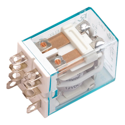
DPDT Relay Module
A Double Pole Double Throw (DPDT) relay is the most straightforward method for controlling actuator direction with an Arduino. The relay acts as an electrically-controlled switch that reverses the polarity of power supplied to the actuator, thereby changing its direction of travel. When selecting a relay module, ensure it meets these specifications:
- Coil Voltage: 5V coil voltage for direct control from Arduino digital pins
- Contact Rating: Must exceed your actuator's current draw, typically 5A minimum for standard actuators, up to 10A for high-current models
- Contact Configuration: True DPDT configuration (6 terminals) necessary for polarity reversal
- Isolation: Optically isolated modules provide additional protection for your Arduino
Power Supply
Your actuator requires a dedicated power supply separate from the Arduino's power. Key considerations include:
- Voltage Rating: Match your actuator's voltage requirement (typically 12V DC)
- Current Capacity: Must provide sufficient current for your actuator under load, plus a 20-30% safety margin. Check your actuator's specifications for peak current draw
- Regulation: A regulated power supply prevents voltage fluctuations that could damage components or cause erratic actuator behavior
- Connector Type: Barrel connectors or screw terminals for secure connections
Additional Components and Accessories
Beyond the core components, you'll need these items to complete your system:
- Jumper Wires: Male-to-male and male-to-female jumper wires for breadboard prototyping, or 18-22 AWG wire for permanent installations
- Breadboard: A standard 830-point breadboard simplifies prototyping and allows easy circuit modifications
- Diode Protection: Flyback diodes (1N4007 or equivalent) to protect against voltage spikes when the actuator motor switches off
- Enclosure: A weatherproof enclosure rated IP65 or higher for outdoor installations, protecting electronics from moisture and dust
- Mounting Hardware: Appropriate mounting brackets for secure actuator installation
- Heat Shrink Tubing: For insulating and protecting soldered connections in permanent installations
Understanding Different Control Methods: Relay vs. Motor Driver
When automating actuator movement with an Arduino, you have several control method options, each with distinct advantages and limitations. The two most practical approaches for timed cycling applications are DPDT relay control and dedicated motor driver control. Understanding the differences helps you select the optimal method for your specific requirements.
DPDT Relay Method: Simple Polarity Reversal
The DPDT relay method works by switching the polarity of the power supply connections to the actuator. When the relay is in one position, positive voltage connects to one actuator terminal and ground to the other, causing extension. When the relay switches positions, the connections reverse, causing retraction. This method offers several advantages:
- Simplicity: Requires minimal components and straightforward wiring
- Cost-Effective: DPDT relays are inexpensive and widely available
- Electrical Isolation: The relay provides galvanic isolation between the Arduino and actuator power circuits
- Full Power: Actuator receives full supply voltage for maximum speed and force
- Robust: Mechanical contacts handle high currents reliably
However, the relay method has limitations. It offers only bang-bang control—the actuator is either moving at full speed in one direction or the other, with no speed control or soft start capability. Position control relies entirely on timing, which can be imprecise due to load variations and mechanical wear. The clicking sound of relay operation may be undesirable in some applications, and mechanical relays have finite lifespans measured in hundreds of thousands of cycles.
Motor Driver Method: Enhanced Control Options
A motor driver (H-bridge) provides electronic switching of actuator polarity using transistors instead of mechanical contacts. Popular options include the L298N, L293D, and more modern MOSFETs-based drivers. This method enables advanced control features:
- PWM Speed Control: Variable speed control through pulse width modulation for gentle starts and stops
- Current Limiting: Built-in current sensing and limiting prevents actuator damage
- Silent Operation: No mechanical clicking or buzzing sounds
- Longer Lifespan: Solid-state switching with no mechanical wear
- Braking Functions: Active braking to stop actuator quickly and hold position under load
Motor drivers do require more complex wiring and programming, consume slightly more power due to voltage drops across the driver circuitry, and typically cost more than simple relays. They also generate heat during operation, requiring adequate ventilation or heat sinking in continuous-duty applications.
Choosing the Right Method for Your Application
For simple timed cycling applications where the actuator extends and retracts on a schedule without intermediate positioning, the DPDT relay method provides the most straightforward and reliable solution. This approach works excellently for applications like automatic vent openers, solar trackers with discrete positions, and periodic mixing systems.
Choose a motor driver when your application requires variable speed control, precise positioning with feedback actuators, soft start/stop to reduce mechanical stress, or integration with more sophisticated control algorithms. Motor drivers also suit applications where silent operation matters, such as home automation projects.
DPDT Relay Method: Wiring and Code Implementation
The DPDT relay method provides the most accessible entry point for Arduino-based actuator control. This section covers the complete implementation, from wiring connections to the working code.
Wiring Configuration
Proper wiring is critical for safe and reliable operation. Follow this connection scheme:
Arduino to Relay Module:
- Arduino Digital Pin 8 → Relay Control Input (IN)
- Arduino GND → Relay GND
- Arduino 5V → Relay VCC (for 5V relay modules)
Relay to Actuator and Power Supply:
- Power Supply Positive (+12V) → Relay COM1
- Power Supply Negative (GND) → Relay COM2
- Relay NO1 (Normally Open 1) → Actuator Wire 1
- Relay NC2 (Normally Closed 2) → Actuator Wire 1
- Relay NC1 (Normally Closed 1) → Actuator Wire 2
- Relay NO2 (Normally Open 2) → Actuator Wire 2
This configuration creates an H-bridge arrangement where energizing the relay reverses the polarity across the actuator terminals. When the relay coil is de-energized, the actuator receives voltage in one polarity. When energized, the polarity reverses, changing the direction of travel.
Complete Arduino Code for Timed Cycling
Here's production-ready code for automatic actuator cycling using a DPDT relay:
// Timed Linear Actuator Control with DPDT Relay
// Automatically extends and retracts actuator at set intervals

// Pin Definitions
const int relayPin = 8;          // DPDT relay control pin
const int statusLED = 13;        // Built-in LED for status indication

// Timing Configuration (all values in milliseconds)
const unsigned long extendTime = 10000;      // Time to fully extend (10 seconds)
const unsigned long retractTime = 10000;     // Time to fully retract (10 seconds)
const unsigned long waitTime = 1800000;      // Wait between cycles (30 minutes)

void setup() {
  // Initialize pins
  pinMode(relayPin, OUTPUT);
  pinMode(statusLED, OUTPUT);

  // Start with relay off (actuator retracting)
  digitalWrite(relayPin, LOW);
  digitalWrite(statusLED, LOW);

  // Initialize serial for debugging (optional)
  Serial.begin(9600);
  Serial.println("Actuator Cycle Controller Started");
  Serial.println("Waiting for first cycle...");
}

void loop() {
  // Wait period before starting cycle
  digitalWrite(statusLED, LOW);
  delay(waitTime);

  // Extend actuator
  Serial.println("Extending actuator...");
  digitalWrite(relayPin, HIGH);    // Energize relay - reverse polarity
  digitalWrite(statusLED, HIGH);    // Turn on status LED
  delay(extendTime);                // Allow time for full extension

  // Stop actuator (optional hold period at extended position)
  digitalWrite(relayPin, LOW);
  delay(1000);                      // Brief pause at full extension

  // Retract actuator
  Serial.println("Retracting actuator...");
  digitalWrite(relayPin, LOW);      // De-energize relay - normal polarity
  digitalWrite(statusLED, LOW);     // Turn off status LED
  delay(retractTime);               // Allow time for full retraction

  Serial.println("Cycle complete. Waiting for next cycle...");
}
Customizing the Code for Your Application
The code structure allows easy modification for different timing requirements and behaviors. Here are the key parameters you can adjust:
Cycle Timing: Modify the waitTime variable to change the interval between cycles. For example, set to 3600000 for hourly cycles, or 300000 for 5-minute intervals. Remember that Arduino's delay() function accepts values in milliseconds.
Actuator Travel Time: Adjust extendTime and retractTime based on your actuator's stroke length and speed. Calculate the required time by dividing stroke length by actuator speed, then add 10-20% buffer to ensure complete travel. For example, a 12-inch stroke at 0.5 inches per second requires 24 seconds, so set the time to 26,000-28,000 milliseconds.
Directional Correction: If your actuator extends when it should retract (or vice versa), simply swap the HIGH and LOW states in the relay control lines. This reverses the polarity without rewiring.
Safety Features and Limit Protection
While the basic code provides reliable timed operation, consider adding these safety enhancements for more robust operation:
Over-Travel Protection: Most quality linear actuators include built-in limit switches that automatically cut power at full extension and retraction. However, always ensure your timing allows the actuator to reach its limits without excess force. Over-driving against mechanical stops can damage the actuator's internal gearbox.
Current Monitoring: For critical applications, add current sensing to detect mechanical binding or obstructions. A sudden spike in current indicates the actuator has encountered resistance and should stop.
Watchdog Timer: Implement Arduino's watchdog timer functionality to automatically reset the controller if the program hangs, ensuring continuous operation in unattended installations.
Alternative Control Methods and Advanced Techniques
Beyond the basic DPDT relay approach, several alternative methods provide enhanced capabilities for specific applications. Understanding these options allows you to select or combine techniques for optimal performance.
H-Bridge Motor Driver Control
An H-bridge motor driver replaces the mechanical relay with solid-state switching, enabling PWM speed control and more sophisticated motion profiles. The L298N is a popular choice for 12V actuators up to 2A per channel, while higher-current applications may require MOSFETs-based drivers like the BTS7960 or VNH5019.
Key advantages of H-bridge control include variable speed through PWM duty cycle adjustment, soft start/stop ramping to reduce mechanical shock, regenerative braking for precise positioning, and silent operation without relay clicking. Implementation requires connecting the motor driver's logic inputs to Arduino PWM-capable pins and using analogWrite() commands to control speed through duty cycle variation.
Feedback-Based Positioning Control
For applications requiring precise positioning rather than simple timing-based cycling, feedback actuators with built-in potentiometers or Hall effect sensors provide real-time position information. The Arduino reads the feedback signal through an analog input and implements closed-loop control to achieve exact positions.
This approach enables intermediate positioning (not just fully extended or retracted), compensation for varying loads that affect speed, position verification before each cycle, and automatic error correction if position drifts over time. Feedback control is essential for applications like adjustable solar panels, precision material handling, or TV lifts that must stop at specific heights.
Real-Time Clock Integration
Adding a real-time clock (RTC) module like the DS3231 transforms your system from interval-based timing to calendar and time-of-day scheduling. This enables sophisticated automation like solar tracking that adjusts actuator position based on time of day and date, greenhouse ventilation that opens at specific temperatures during daylight hours only, or security applications that change behavior based on whether it's day or night.
RTC modules maintain accurate timekeeping even when the Arduino is powered off, using a coin cell battery for backup. They communicate with the Arduino via I2C, requiring only two data lines plus power connections.
Sensor-Conditional Operation
Combining timed cycling with environmental sensors creates responsive automation systems. Common sensor integrations include:
- Temperature Sensors: DHT22 or DS18B20 sensors trigger ventilation actuators when temperature exceeds thresholds
- Light Sensors: Photoresistors or TSL2561 digital light sensors enable actuators for automatic blinds or greenhouse shading
- Moisture Sensors: Soil moisture or rain sensors control irrigation system actuators based on actual conditions
- Limit Switches: External limit switches provide redundant over-travel protection and position verification
Sensor integration requires reading analog or digital inputs within the main loop and implementing conditional logic to modify actuator behavior based on sensor readings while maintaining the basic timed cycling structure.
Multiple Actuator Coordination
Many automation projects require coordinating multiple actuators in sequence or parallel. The Arduino's multiple digital outputs support controlling several relay modules or motor drivers simultaneously. Best practices include using a control box with integrated relays for multi-actuator systems, implementing staggered start times to prevent power supply overload, creating state machine logic to coordinate complex motion sequences, and monitoring current draw to ensure the power supply can handle simultaneous operation.
For projects requiring more than 4-6 actuators, consider using relay multiplexer boards or upgrading to an Arduino Mega with expanded I/O capabilities. Industrial applications may benefit from purpose-built industrial actuators with integrated controllers.
Troubleshooting Common Issues and Optimization Tips
Even with proper wiring and code, you may encounter challenges during implementation. Here are solutions to common problems and optimization strategies for reliable operation.
Actuator Not Responding
If your actuator fails to move when the relay clicks or the motor driver activates, check these potential issues:
Power Supply Issues: Verify the power supply voltage matches the actuator specification and can deliver sufficient current. Measure voltage at the actuator terminals during operation—if it drops significantly below the rated voltage, your power supply is undersized or has poor regulation. Also check for loose connections or corroded terminals that create high resistance.
Wiring Errors: Double-check that the relay or motor driver connections match the wiring diagram exactly. A common mistake is connecting both actuator wires to the same relay pole, which prevents current flow. Use a multimeter to verify voltage polarity at the actuator terminals changes when the relay switches.
Internal Actuator Limits: Quality linear actuators include internal limit switches that prevent over-extension and retraction. If the actuator is already at a limit position, it will only move in the opposite direction. Manually verify the actuator isn't mechanically bound at a limit.
Erratic or Inconsistent Behavior
Intermittent operation or unpredictable actuator movement indicates electrical or timing issues:
Voltage Fluctuations: Inadequate power supply filtering causes voltage spikes and drops that disrupt Arduino operation. Add a 1000µF capacitor across the power supply output terminals near the actuator to smooth voltage transients. Ensure the Arduino receives clean 5V power, ideally through its USB port or a dedicated regulated 5V supply rather than sharing the actuator's 12V supply.
Electrical Noise: The actuator's brushed DC motor generates electrical noise that can couple into Arduino circuits through ground loops or radiated interference. Solutions include physically separating Arduino and actuator power grounds, connecting them at only a single point, adding 0.1µF ceramic capacitors directly across the actuator motor terminals to suppress noise, using shielded cable for long actuator wire runs, and implementing software debouncing if using limit switches or sensors.
Timing Accumulation Errors: Arduino's delay() function isn't perfectly precise, and small timing errors accumulate over many cycles. For applications requiring precise scheduling over hours or days, replace delay() with millis()-based timing or add an RTC module for accurate long-term timekeeping.
Insufficient Force or Slow Operation
If the actuator moves but lacks the expected force or speed:
Voltage Drop Under Load: Measure actuator terminal voltage while the actuator is pushing or pulling its load. If voltage drops more than 1-2V from the no-load value, your power supply or wiring can't deliver adequate current. Upgrade to a higher-current power supply or use heavier gauge wire to reduce resistance.
Actuator Undersized: Verify your actuator's force rating exceeds the application's load requirements with adequate safety margin. Operating an actuator near its maximum rated force reduces speed and lifespan. Consider upgrading to industrial actuators for higher force applications.
Mechanical Binding: Check for misalignment, inadequate lubrication, or mechanical interference in the actuator mounting. The actuator shaft should move smoothly through its full stroke when disconnected from the load. Ensure mounting brackets allow the actuator to pivot freely at both ends.
Relay Failures or Shortened Lifespan
Mechanical relays wear out over time, especially when switching inductive loads like actuator motors:
Contact Arcing: The actuator's motor inductance causes voltage spikes when power is switched off, creating arcs across relay contacts that pit and erode them. Add a snubber circuit (a 0.1µF capacitor in series with a 100Ω resistor) across the relay contacts to suppress arcing. Some motor drivers include this protection internally.
Current Rating: Ensure the relay's contact rating significantly exceeds the actuator's peak current draw, including the 2-3x inrush current spike when first powered. A relay rated for only slightly more than the actuator's running current will fail prematurely.
Switching Frequency: Mechanical relays aren't designed for rapid cycling. If your application requires switching more frequently than once per minute, consider upgrading to a solid-state relay (SSR) or motor driver for unlimited cycle life.
Performance Optimization Strategies
Enhance reliability and efficiency with these optimization techniques:
- Soft Start Timing: Add a brief power-on ramp when using PWM motor drivers to reduce mechanical stress on gears and mounting hardware
- Position Verification: If using feedback actuators, verify the actuator reached the target position before starting the wait timer
- Power Management: Implement sleep modes during long wait periods to reduce power consumption in battery-powered applications
- Duty Cycle Monitoring: Track cumulative actuator run time and enforce rest periods to stay within the manufacturer's specified duty cycle
- Environmental Protection: Use conformal coating on circuit boards for outdoor installations, and ensure enclosures maintain appropriate operating temperatures
Practical Applications and Project Ideas
Arduino-controlled actuators enable automation across countless applications. Here are proven implementations that demonstrate the versatility of timed cycling systems.
Agricultural and Greenhouse Automation
Automated ventilation systems use linear actuators to open and close greenhouse vents on a temperature-based schedule. The system can cycle vents open during peak heat hours and close them at night to retain warmth. Automatic watering systems for livestock use actuators to operate large valves on a timed schedule, ensuring consistent water availability. Chicken coop doors that open at sunrise and close at dusk protect poultry while eliminating manual operation, with timing adjusted seasonally using an RTC module.
Solar Energy Systems
Solar panel tracking systems maximize energy capture by adjusting panel orientation throughout the day. A simple two-position tracker uses timed actuator cycling to move panels from an east-facing morning position to a west-facing afternoon position. More sophisticated systems use multiple actuators for dual-axis tracking, adjusting both azimuth and elevation angles based on time and date calculations. Automated solar oven reflector positioning optimizes cooking performance by tracking the sun's position.
Home Automation Projects
Automated window blinds and skylights improve home comfort and energy efficiency. Actuators extend to open blinds in the morning and retract to close them in the evening, with schedules adjusted seasonally. TV lifts and hidden projector screens create clean, minimalist spaces by concealing electronics when not in use. Drawer slides with actuators enable automatic opening for hidden storage compartments activated by RFID cards or remote controls.
Industrial and Manufacturing Applications
Material handling systems use synchronized multiple actuators to move parts through processing stages on timed cycles. Automated sorting gates in conveyor systems use fast-cycling actuators to direct items to appropriate bins. Industrial actuators control valve positioning in fluid systems, cycling open and closed to meter flow rates or implement batch processing. Automated welding and assembly fixtures use actuators to position workpieces precisely for each operation step.
Kinetic Art and Entertainment
Kinetic sculptures incorporate actuators for mesmerizing motion art that cycles through choreographed movements. Stage automation systems use actuators for prop movement, trapdoors, or scenic element positioning synchronized to show timing. Interactive museum exhibits employ actuators to create engaging hands-on experiences with timed demonstrations or reveals. Escape room mechanisms use hidden actuators to create surprising reveals and mechanical puzzles.
Accessibility and Ergonomics
Automated accessibility ramps deploy and retract on schedules matching building hours or can be activated remotely. Standing desk systems with Arduino control enable programmable position presets that automatically adjust desk height at scheduled intervals throughout the workday, encouraging ergonomic variety. Automated lifting systems help caregivers with patient transfer tasks on predictable schedules.
Advanced Programming Techniques
Once you've mastered basic timed cycling, these advanced programming concepts enable more sophisticated actuator control systems.


