In the world of motion control and automation, few techniques have proven as versatile and effective as Pulse-Width Modulation (PWM). Whether you're designing a precision linear actuator system, controlling motor speed in robotics, or synchronizing multiple motion components, understanding PWM is essential. This digital control method allows engineers and hobbyists alike to achieve analog-like precision using simple on-off switching, making it the backbone of modern electronic control systems.
🎥 Video — Pulse-width Modulation (PWM): A Comprehensive Guide to Precision Control
At FIRGELLI Automations, we've spent over two decades engineering electric actuation systems that leverage PWM for precise, reliable control. From our feedback actuators to sophisticated multi-actuator synchronization systems, PWM enables the level of control that our customers demand. This guide will take you beyond the basics, exploring not just what PWM is, but how to optimize it for real-world applications involving DC motors, linear actuators, and complex motion control scenarios.
Whether you're troubleshooting motor response issues, designing a custom automation project, or simply curious about the technology powering modern motion control, this comprehensive guide will equip you with the knowledge to harness PWM effectively.
Fundamentals of Pulse-Width Modulation
Pulse-Width Modulation is a digital technique that creates an analog-like effect by rapidly switching a signal between ON (high voltage) and OFF (low voltage or ground) states. Unlike true analog control, which varies voltage continuously, PWM maintains a constant voltage amplitude but changes the ratio of time spent in the ON state versus the OFF state within each cycle.
Think of PWM as a highly efficient dimmer switch. A traditional analog dimmer reduces the voltage supplied to a light bulb, wasting energy as heat. PWM, by contrast, delivers full voltage but only for a fraction of each cycle, achieving the same dimming effect with dramatically better efficiency. This principle applies equally whether you're controlling LED brightness, motor speed, or the precise positioning of an actuator.
The key advantage of PWM lies in its digital nature. Because the signal is always either fully ON or fully OFF, switching components like MOSFETs and transistors operate in their most efficient states—either fully conducting or fully blocking current. This minimizes heat generation and power loss, making PWM ideal for battery-powered applications and high-power systems alike.
Anatomy of a PWM Signal
Understanding the components of a PWM signal is crucial for effective implementation. A typical PWM signal exhibits several measurable characteristics that determine its behavior and effectiveness.
Frequency and Period
The frequency of a PWM signal, measured in Hertz (Hz), defines how many complete ON-OFF cycles occur per second. The inverse of frequency is the period—the time duration of one complete cycle. For example, a 1 kHz PWM signal completes 1,000 cycles per second, with each cycle lasting 1 millisecond.
Frequency selection depends heavily on your application. Low frequencies (50-500 Hz) work well for applications with high inertia, such as industrial actuators moving heavy loads, where rapid switching would be imperceptible. Higher frequencies (1-20 kHz) are preferred for applications requiring smooth operation and minimal audible noise, such as precision positioning systems or TV lifts in quiet environments.
Duty Cycle
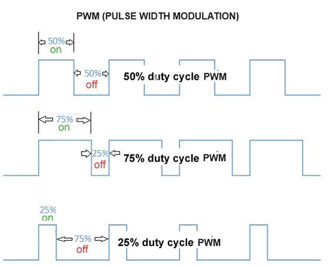
The duty cycle represents the percentage of time the signal remains in the ON state during each period. A 50% duty cycle means the signal is ON for half the cycle and OFF for the other half. A 75% duty cycle indicates the signal is ON for three-quarters of each cycle. This ratio directly correlates to the average power delivered to the load.
For motor control applications, duty cycle translates almost directly to speed (assuming constant load). A 25% duty cycle typically yields approximately 25% of maximum speed, while a 75% duty cycle produces roughly 75% of maximum speed. However, this relationship isn't perfectly linear due to factors like motor efficiency curves, back-EMF, and friction characteristics.
Rise and Fall Times
Real-world PWM signals don't switch instantaneously. The rise time is how long the signal takes to transition from low to high voltage, while fall time describes the high-to-low transition. These transitions are typically measured in nanoseconds to microseconds, depending on the switching components used.
For most motor and actuator control applications, rise and fall times are negligible. However, in high-frequency applications or when using long cable runs, these transition times can affect signal integrity and may require consideration in circuit design, including proper PCB layout and filtering components.
PWM Control for DC Motors and Actuators
DC motors and electric actuators represent the most common application of PWM in motion control systems. The beauty of PWM lies in its ability to provide infinitely variable speed control while maintaining full torque availability at any speed—a characteristic that sets electric actuation apart from hydraulic and pneumatic alternatives.
Brushed DC Motors
Brushed DC motors respond intuitively to PWM signals. The rotating armature and stationary permanent magnets create a straightforward relationship between applied voltage and rotational speed. When you apply a PWM signal to a brushed motor, the motor's mechanical inertia and electrical inductance naturally smooth out the pulsed input, resulting in relatively steady rotation.
The motor's inductance acts as a natural low-pass filter, maintaining current flow even during the OFF periods of the PWM cycle. This is why a motor receiving a 50% duty cycle doesn't stutter on and off, but instead rotates smoothly at approximately half speed. The armature continues rotating through the OFF periods due to its inertia, while the magnetic field in the windings decays gradually rather than instantly.
Brushless DC Motors (BLDC)
Brushless DC motors require more sophisticated PWM control because they lack mechanical commutation. Instead, electronic speed controllers (ESCs) must precisely time PWM signals to multiple motor phases, creating the rotating magnetic field that drives the rotor. Modern BLDC controllers use techniques like sinusoidal commutation or field-oriented control (FOC) to maximize efficiency and minimize torque ripple.
While BLDC motors offer superior efficiency and longevity compared to brushed motors, their control requirements are significantly more complex. Most hobbyist and commercial applications rely on dedicated BLDC controllers that handle the intricate timing internally, accepting a simple PWM input signal for speed control.
Linear Actuator Control
Electric linear actuators are essentially DC motors coupled with mechanical transmission systems—typically lead screws, ball screws, or planetary gear systems. PWM control of actuators follows the same principles as motor control but with additional considerations for position, load, and mechanical constraints.
When controlling actuators with PWM, you're managing not just speed but also the force characteristics throughout the stroke. A micro linear actuator moving a light load may respond crisply to duty cycle changes, while an industrial actuator pushing 1,000 pounds might exhibit more inertial lag and require carefully tuned PWM parameters to avoid mechanical shock or premature wear.
Motor Characteristics and PWM Optimization
Not all motors respond identically to PWM signals. Understanding the physical characteristics of your motor or actuator is essential for optimizing PWM parameters and achieving the desired performance.
Physical Size and Inertia
Larger motors with greater rotor mass exhibit higher rotational inertia, which affects their response to PWM control. High-inertia motors act as mechanical low-pass filters, smoothing out PWM fluctuations but also responding more slowly to duty cycle changes. This characteristic can be advantageous when smooth, steady motion is required, but problematic when rapid speed changes are necessary.
For applications requiring quick response, such as robotic systems or precision positioning equipment, lower-inertia motors paired with higher PWM frequencies (10-20 kHz) typically yield optimal results. Conversely, heavy-duty applications like TV lifts or large column lifts may perform better with moderate PWM frequencies (1-5 kHz) that complement the system's inherent mechanical damping.
Torque Requirements and Load Matching
Motor torque characteristics significantly influence PWM control strategy. Most DC motors produce maximum torque at stall (zero RPM) and less torque as speed increases. The torque-speed curve is roughly linear for brushed DC motors, while BLDC motors can maintain more consistent torque across their speed range.
When controlling actuators under heavy loads, you may need higher minimum duty cycles to overcome static friction and initiate motion. Many control boxes and motor controllers implement "soft start" algorithms that gradually increase duty cycle during startup, preventing excessive current draw and mechanical shock. This is particularly important for track actuators and other systems with high static loads.
Electrical Time Constant
Every motor possesses an electrical time constant (L/R ratio) determined by its inductance and resistance. This parameter affects how quickly current can change in the motor windings. Motors with large inductances—typically larger, higher-voltage motors—smooth out PWM signals more effectively but may require higher PWM frequencies to avoid torque ripple and audible noise.
Small motors, particularly micro actuators with low inductance, may exhibit more pronounced current fluctuations at low PWM frequencies. These applications often benefit from frequencies above 10 kHz, which moves any acoustic emissions above the audible range and provides smoother current delivery.
Practical PWM Implementation Strategies
Successfully implementing PWM control requires attention to both electronic design and mechanical considerations. Here are key factors that separate reliable, professional implementations from problematic ones.
Frequency Selection Guidelines
Choose PWM frequency based on several factors: motor characteristics, desired response time, acoustic considerations, and switching losses. For most linear actuator applications, frequencies between 1 kHz and 20 kHz provide optimal performance. Lower frequencies (100-500 Hz) are adequate for very large motors with high inductance but may produce audible whine. Frequencies above 20 kHz push into the ultrasonic range, eliminating acoustic noise but increasing switching losses in the drive electronics.
When controlling multiple actuators simultaneously, consistent PWM frequency across all channels is crucial. This prevents beat frequencies and interference that could cause uneven motion or unpredictable behavior. Professional control systems maintain synchronized PWM generation across all outputs to ensure harmonious operation.
MOSFET and Driver Selection
The switching components in your PWM circuit critically affect performance. Modern MOSFETs offer excellent switching characteristics, but proper gate drive circuitry is essential. Inadequate gate drive can lead to slow switching transitions, increased heat generation, and potential MOSFET failure. Most applications benefit from dedicated gate driver ICs that can deliver the high peak currents needed for rapid MOSFET switching.
For high-current applications, such as controlling multiple industrial actuators simultaneously, parallel MOSFETs or specialized high-current modules may be necessary. Proper thermal management becomes critical in these scenarios, with adequate heatsinking and thermal interface materials preventing component failure.
Filtering and EMI Considerations
PWM signals generate electromagnetic interference (EMI) due to their rapid switching nature. Proper circuit design includes filtering capacitors near the motor terminals to suppress high-frequency noise, and potentially ferrite beads or common-mode chokes on long cable runs. This is particularly important in noise-sensitive environments or when using feedback actuators where sensor signals could be corrupted by electrical noise.
Additionally, freewheeling diodes (or the body diodes in H-bridge configurations) must be rated for the motor's inductive kick. When PWM switches OFF, the motor's inductance generates a voltage spike that these diodes must safely dissipate. Inadequate diode ratings can lead to premature failure and unreliable operation.
Multi-Actuator Synchronization with PWM
One of PWM's most valuable capabilities is enabling precise synchronization of multiple actuators—essential for applications ranging from adjustable furniture to complex industrial machinery. Synchronized motion prevents mechanical binding, uneven loading, and premature wear in systems with multiple motion axes.
The Challenge of Synchronization
Even supposedly identical actuators exhibit slight variations in speed due to manufacturing tolerances, load differences, and friction variations. Without active synchronization, these differences compound over time, causing one actuator to lead or lag the others. In applications like standing desks or large platform lifts, this misalignment can create dangerous binding forces or damage the mechanism.
Traditional solutions involved mechanical linkages or complex gear trains to force synchronization. Modern electronic synchronization using PWM and feedback control offers superior performance with greater flexibility and easier installation.
The FIRGELLI FCB-1 Control System
The FIRGELLI FCB-1 exemplifies advanced PWM-based synchronization. This control box manages up to four feedback actuators simultaneously, using real-time position data to adjust individual PWM duty cycles and maintain perfect alignment throughout the entire stroke.
The FCB-1's synchronization algorithm continuously monitors each actuator's position via built-in Hall effect sensors or potentiometers. If one actuator begins to lag, the controller automatically increases its duty cycle while slightly reducing the duty cycle of leading actuators. This dynamic adjustment happens hundreds of times per second, maintaining alignment within millimeters across the entire travel range.
Beyond basic synchronization, the FCB-1 implements sophisticated speed control, allowing users to adjust overall system speed from 0-100% while maintaining perfect coordination between all connected actuators. This capability is invaluable in applications requiring variable speed control, such as adjustable workstations, automated doors, or custom automation projects.
Feedback Requirements for Synchronization
Effective multi-actuator synchronization requires position feedback from each actuator. While basic open-loop PWM control can approximate synchronized motion, only closed-loop feedback systems can maintain precise alignment under varying loads and conditions. Feedback actuators with integrated Hall sensors or potentiometers provide the real-time position data necessary for accurate synchronization.
The feedback signal allows the controller to implement proportional-integral-derivative (PID) control algorithms that not only correct position errors but also predict and compensate for dynamic changes. This results in smooth, vibration-free motion even when loads shift or external forces are applied during operation.
Advanced PWM Applications in Motion Control
Beyond basic speed control, PWM enables sophisticated motion control capabilities that elevate simple actuator systems into precision automation solutions.
Ramping and Acceleration Control
Abrupt speed changes can shock mechanical systems, causing wear, noise, and reduced component life. Professional motion control systems implement duty cycle ramping—gradually increasing or decreasing duty cycle over time to smoothly accelerate or decelerate. This is particularly important for heavy loads, such as TV lifts supporting expensive displays, where sudden stops could cause damage.
Acceleration profiles can be linear (constant rate of change) or curved (S-curve profiles) depending on application requirements. S-curves provide the smoothest motion by gradually increasing acceleration at the beginning and end of each move, minimizing jerk (rate of change of acceleration) and resulting in exceptionally smooth, professional-feeling motion.
Current Limiting and Motor Protection
PWM systems can implement current limiting by monitoring motor current and automatically reducing duty cycle when current exceeds safe thresholds. This protects both the motor and drive electronics from damage due to stalls, excessive loads, or fault conditions. Advanced systems implement current-based load detection, recognizing when an actuator reaches an obstruction or end-of-travel and stopping motion before damage occurs.
Position-Based Speed Profiles
When combined with position feedback, PWM enables sophisticated position-dependent speed control. For example, a TV lift might operate at high speed through the middle of its stroke but automatically slow down as it approaches fully extended or retracted positions, providing smooth, controlled arrival at each endpoint without jarring stops or mechanical shock.
Troubleshooting PWM Control Systems
Understanding common PWM-related issues helps diagnose problems and optimize system performance.
Motor Won't Start at Low Duty Cycles
If a motor or actuator fails to move until duty cycle exceeds 30-40%, this typically indicates high static friction or insufficient torque at low speeds. Solutions include increasing PWM frequency (to reduce torque ripple), implementing a higher-current power supply, or using a "kick-start" algorithm that briefly applies higher duty cycle to overcome static friction before settling to the desired speed.
Audible Noise or Whining
Acoustic noise from PWM control usually stems from PWM frequencies in the audible range (below 20 kHz) exciting mechanical resonances in the motor or actuator. Increasing PWM frequency above 20 kHz typically eliminates this issue. Alternatively, adding mechanical damping or securing loose components can reduce resonance.
Erratic Speed or Stuttering
Unstable motor operation often indicates electrical noise affecting the PWM signal or insufficient power supply capacity. Check for proper grounding, adequate bypass capacitors near the motor driver, and ensure the power supply can deliver peak current demands. Long cable runs may require shielded cables or reduced PWM frequency to maintain signal integrity.
Excessive Heating
If MOSFETs or motor drivers run excessively hot, this suggests inefficient switching. Verify proper gate drive voltages, adequate gate driver current capacity, and appropriate MOSFET selection for the switching frequency. Higher PWM frequencies require MOSFETs with lower gate charge specifications to minimize switching losses.
The Future of PWM in Motion Control
As motion control technology evolves, PWM remains central to emerging innovations. Modern microcontrollers and DSPs offer hardware PWM generation with resolutions exceeding 16 bits, enabling extraordinarily precise speed control. Integration with communication protocols like CANbus, Modbus, and EtherCAT allows PWM-controlled actuators to participate in sophisticated industrial automation networks.
Emerging technologies like silicon carbide (SiC) and gallium nitride (GaN) semiconductors enable PWM switching at frequencies exceeding 100 kHz with minimal losses, opening new possibilities for ultra-compact, highly efficient motor drives. These advanced semiconductors can handle higher temperatures and voltages, making them ideal for demanding industrial applications.
Machine learning and adaptive control algorithms are beginning to optimize PWM parameters automatically based on load conditions, temperature, and wear patterns. These intelligent systems can extend component life and maintain optimal performance throughout the actuator's service life, representing the next generation of motion control sophistication.
Conclusion
Pulse-Width Modulation stands as a fundamental technique in modern motion control, enabling precise, efficient management of motors and actuators across countless applications. From the simplest hobby project to sophisticated industrial automation systems, PWM provides the control granularity and efficiency that make electric actuation superior to hydraulic and pneumatic alternatives.
At FIRGELLI Automations, we've built our product line around PWM control principles, developing linear actuators, control systems, and complete motion solutions that leverage PWM for reliable, precise operation. Whether you're selecting actuators for a new project or optimizing an existing system, understanding PWM fundamentals and best practices ensures successful implementation and long-term reliability.
The versatility of PWM continues to expand as electronic components improve and control algorithms become more sophisticated. By mastering the principles outlined in this guide, you'll be well-equipped to design, implement, and troubleshoot PWM-based motion control systems that meet the demanding requirements of modern automation applications.
Frequently Asked Questions
What PWM frequency should I use for linear actuator control?
For most linear actuator applications, PWM frequencies between 1 kHz and 20 kHz provide optimal performance. Smaller micro actuators with low inductance motors perform best at higher frequencies (10-20 kHz), which eliminates audible noise and provides smooth current delivery. Larger industrial actuators with higher inductance motors work well at lower frequencies (1-5 kHz). If you hear audible whining or buzzing from your actuator, increase the PWM frequency above 20 kHz to push acoustic emissions beyond the audible range. The mechanical system's inertia also influences optimal frequency—high-inertia systems naturally filter PWM fluctuations and may perform adequately at lower frequencies.
Can I synchronize multiple actuators without feedback sensors?
While basic open-loop PWM control can approximate synchronized motion by applying identical duty cycles to multiple actuators, it cannot maintain precise alignment over time or under varying loads. Manufacturing tolerances, friction differences, and load variations cause actuators to drift out of sync even when receiving identical control signals. For reliable, precise synchronization—essential in applications like standing desks, platform lifts, or adjustable furniture—you need feedback actuators with integrated position sensors and a controller (like the FIRGELLI FCB-1) that can dynamically adjust individual actuator speeds to maintain alignment. The modest additional cost of feedback-equipped actuators is worthwhile in any application where misalignment could cause binding, uneven loading, or safety concerns.
Why doesn't my motor speed change proportionally with duty cycle?
Several factors prevent perfectly linear speed-to-duty-cycle relationships. First, motors require a minimum duty cycle to overcome static friction and begin moving—typically 15-30% depending on motor characteristics and load. Below this threshold, the motor may not move at all. Second, motor efficiency varies across the speed range due to back-EMF (electromotive force generated by rotation), bearing friction, and aerodynamic drag. Third, load characteristics significantly affect the relationship—motors under heavy load require higher duty cycles to achieve the same speed as unloaded motors. Finally, at very low duty cycles, torque ripple becomes pronounced, causing uneven rotation. For applications requiring precise speed control, closed-loop control using tachometer feedback or current sensing provides much better accuracy than open-loop duty cycle adjustment alone.
What causes MOSFETs to overheat in PWM motor control circuits?
MOSFET overheating in PWM applications typically results from excessive switching losses or inadequate thermal management. Switching losses occur during the brief transitions between ON and OFF states when the MOSFET passes through its linear region, dissipating significant power. Slow switching—caused by inadequate gate drive current or excessive gate charge—increases these losses. Solutions include using dedicated gate driver ICs that can deliver high peak currents, selecting MOSFETs with lower gate charge (Qg) specifications for your switching frequency, and ensuring proper gate drive voltages (typically 10-15V for logic-level MOSFETs). Additionally, verify adequate heatsinking using properly sized heatsinks with thermal interface material, and ensure MOSFETs are rated for both the continuous and peak currents in your application. For high-current applications controlling multiple industrial actuators, parallel MOSFETs or specialized high-current motor driver modules may be necessary.
How do I implement PWM control using Arduino or other microcontrollers?
Most modern microcontrollers, including Arduino boards, provide hardware PWM generation through dedicated timer peripherals. On Arduino, use the analogWrite() function with a pin number and duty cycle value (0-255, corresponding to 0-100% duty cycle). Arduino Uno provides hardware PWM on pins 3, 5, 6, 9, 10, and 11 at approximately 490 Hz (pins 5 and 6 operate at 980 Hz). For more precise control, you can adjust timer registers to modify PWM frequency, though this requires understanding the specific microcontroller's timer architecture. When controlling motors or actuators directly from a microcontroller, always use a motor driver IC or MOSFET circuit rather than connecting motors directly to microcontroller pins—microcontroller outputs can typically source only 20-40 mA, while even small motors draw hundreds of milliamps to several amperes. Popular motor driver ICs like the L298N, DRV8833, or TB6612FNG accept PWM inputs from microcontrollers and provide adequate current capacity for most hobby and light-duty applications.


