How do you control a linear actuator with a push button and Arduino?
Push button control with Arduino is a method of driving a 12V DC linear actuator through an H-bridge motor driver, using momentary switches wired to Arduino digital inputs to command extend, retract, and stop movement.
Controlling linear actuators with physical push buttons remains one of the most intuitive and reliable interface methods for automation projects. Whether you're building a motorized cabinet, adjustable workbench, or custom automation system, understanding how to implement button control through an Arduino provides the foundation for sophisticated motion control applications.
This comprehensive tutorial demonstrates two distinct control modes: momentary operation (where the actuator moves only while the button is pressed) and sustaining operation (where the actuator continues moving after button release until stopped). Both modes have specific use cases in real-world applications, and we'll explore the hardware, wiring, and programming for each approach. This guide builds upon concepts introduced in motor driver control fundamentals, particularly H-bridge operation and PWM speed control that enable bidirectional actuator movement.
Before proceeding, you should have basic familiarity with Arduino programming, circuit assembly, and electrical safety when working with 12V DC systems. While this tutorial provides complete working code and wiring diagrams, understanding the underlying principles will help you adapt these techniques to your specific project requirements.
Wiring and power delivery matter as much as the actuator itself. An undersized supply or a loose ground will mimic every symptom of a failing actuator.
"The power supply is where most push-button actuator builds fail. People size for the running current and forget the actuator pulls its stall current every time it hits a hard stop. Pick a supply rated at least 50% above stall, and the rest of the circuit behaves." — Robbie Dickson, Founder and Chief Engineer of FIRGELLI Automations
What components do you need for push-button actuator control?
Successful implementation requires the correct components matched to your application requirements. Here's what you'll need along with selection considerations:
Linear Actuator Selection
Any 12V DC linear actuator will work with this setup. For compact projects, consider micro linear actuators which offer stroke lengths from 10mm to 100mm and force ratings up to 150N. For applications requiring position feedback, feedback actuators with built-in potentiometers enable precise positioning control in more advanced implementations. Standard force ratings range from 50N to 1500N depending on your load requirements.
Power Supply Requirements
Your power supply must provide sufficient current for your actuator's stall current rating, typically 2-6A for most actuators. A 12V 5A supply handles most single actuator applications with adequate headroom. Ensure the supply voltage matches your actuator specification—most FIRGELLI actuators operate at 12V DC, though some models are available in 24V configurations for higher force applications.
Arduino Board
Any Arduino board with at least 4 digital I/O pins will work. The Arduino Uno is recommended for beginners due to its widespread support and documentation. Arduino Nano or Micro boards work well for space-constrained installations. The code provided is compatible with all standard Arduino boards without modification.
Motor Driver Module
An H-bridge motor driver is essential for bidirectional actuator control. The L298N module is widely available and handles up to 2A per channel, suitable for most actuators. For higher current applications, consider the BTS7960 driver (43A capability) or VNH5019 (12A capability). The driver must handle your actuator's peak current draw with at least 20% safety margin.
Motor driver selection for push-button actuator control:
| Driver | Continuous current | Typical use |
|---|---|---|
| L298N | up to 2 A/channel | Standard and micro actuators (most 12V projects) |
| VNH5019 | up to 12 A | Higher-current single actuators |
| IBT-2 (BTS7960-based) | High-current | Larger actuators or multiple units |
| BTS7960 | up to 43 A | Industrial actuators, high stall-current loads |
Note: size the driver for at least 120% of the actuator's stall current.
Momentary Push Buttons
Standard momentary (normally open) push buttons work perfectly for this application. Choose buttons rated for at least 50mA at 5V for the digital signal lines. Buttons with built-in LED indicators provide visual feedback of system state. For panel mounting, 16mm push buttons with screw terminals simplify installation in enclosures.
Wiring and Connection Materials
Use 22-24 AWG stranded wire for Arduino signal connections and 16-18 AWG wire for power connections to the motor driver and actuator. Ferrule crimp terminals or proper soldering ensure reliable connections. Heat shrink tubing protects connections from shorts. For permanent installations, consider terminal blocks for maintainable connections.
How does momentary control mode work?
Momentary control provides the most intuitive operation for many applications—the actuator moves only while you hold the button pressed, stopping immediately when released. This mode is ideal for applications requiring precise manual positioning, such as adjustable height mechanisms, fine positioning systems, or any application where accidental continuous movement would be problematic.
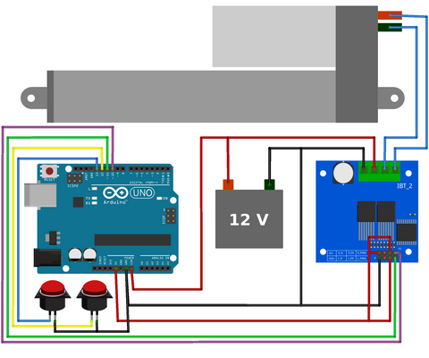
Wiring Diagram for Momentary Control
The wiring configuration uses two momentary switches connected to Arduino digital pins with internal pull-up resistors enabled in software. Connect the first button between Arduino pin 6 and GND for extending the actuator, and the second button between pin 7 and GND for retracting. The motor driver's direction control pins connect to Arduino pins 2 and 3, while the PWM speed control pin connects to pin 5.
Power connections require careful attention: connect the 12V power supply positive terminal to the motor driver's VCC input and the negative terminal to GND. The Arduino can be powered either through its barrel jack, USB connection, or from the motor driver's 5V output if available. Ensure all ground connections are common between the Arduino, motor driver, and power supply.
Code Explanation: Momentary Mode
The momentary control code implements a simple but effective logic structure. During setup, the code configures pins 2, 3, and 5 as outputs for motor driver control, while pins 6 and 7 are configured as inputs with internal pull-up resistors enabled. This means the pins normally read HIGH and go LOW when a button is pressed, eliminating the need for external resistors.
The main loop continuously reads both button states using digitalRead(). When the extend button (pin 6) reads LOW, the code sets the appropriate direction pins and applies PWM to pin 5, causing the actuator to extend. When the retract button (pin 7) reads LOW, the direction reverses. If neither button is pressed, both direction pins are set LOW and PWM output stops, immediately halting actuator movement. This provides instant response to button release.
The PWM value on pin 5 controls actuator speed. The example uses analogWrite(5, 255) for maximum speed, but this value can range from 0 (stopped) to 255 (full speed). Reducing this value to 180-200 provides slower, more controlled movement for applications requiring gentle positioning.
Code for Momentary Control
View the momentary control Arduino sketch on GitHub Gist
How does sustaining (latching) control mode work?
Sustaining control mode allows the actuator to continue moving after button release, useful for applications with long stroke lengths where holding a button for extended periods is impractical. This mode mimics latching relay behavior—press once to start movement, press stop to halt. Applications include window openers, large TV lifts, and automated door systems where full travel time might exceed 30 seconds.
Three-Button Configuration
Sustaining mode requires three buttons instead of two: an extend button, a retract button, and a stop button. The stop button connects to pin 8 and GND, while extend and retract buttons remain on pins 6 and 7. This configuration prevents the actuator from continuing movement indefinitely, providing essential safety functionality.
The stop button serves multiple purposes beyond its obvious function. It acts as an emergency stop during operation, allows precise positioning by stopping movement at any point, and prevents actuator damage from over-travel by enabling manual intervention before limit switches engage.
State Machine Logic Implementation
The sustaining control code implements a state machine—a programming pattern that tracks the current operational mode (stopped, extending, or retracting) and transitions between states based on button presses. This is more sophisticated than the simple momentary control and demonstrates intermediate Arduino programming concepts.
The code uses a variable to store the current state: 0 for stopped, 1 for extending, and 2 for retracting. When a button is pressed, the code checks the current state and determines the appropriate action. Pressing extend while stopped starts extension and changes state to 1. Pressing stop from any active state returns to state 0. This logic prevents conflicting commands and ensures predictable behavior.
Button debouncing is handled through simple delay statements after detecting button presses. While not the most elegant solution for production applications, it prevents false triggers from mechanical switch bounce—the brief electrical noise when physical contacts close. For more robust implementations, consider implementing software debouncing with millis() timing or adding hardware debounce capacitors.
Code for Sustaining Control
View the sustaining control Arduino sketch on GitHub Gist
What advanced features can you add to a button-controlled actuator?
Current Limiting and Overcurrent Protection
Linear actuators draw significant current during startup and when stalled against mechanical stops. Implementing current sensing through the motor driver's current sense output enables software-based stall detection. When current exceeds a threshold for more than 500ms, the code can automatically stop movement, protecting both actuator and driver from damage. This is particularly important for applications without mechanical limit switches.
Integrating Position Feedback
For applications requiring precise positioning, feedback actuators with integrated potentiometers provide analog position signals. Reading this feedback through Arduino analog inputs enables closed-loop control—automatically stopping at specific positions, implementing soft start/stop motion profiles, and detecting obstruction through unexpected position changes. This transforms simple button control into sophisticated automation.
External Limit Switch Integration
Adding external limit switches at full extension and retraction prevents actuator damage from over-travel. Connect normally-closed limit switches in series with the motor driver enable pin, or monitor them through Arduino digital inputs for software-controlled stopping. This provides redundant protection beyond actuator internal limits, especially valuable in high-force applications where mechanical damage could occur.
Controlling Multiple Actuators
The basic code structure scales to control multiple actuators by replicating the motor driver connections and pin assignments. For synchronized movement of multiple actuators (common in TV lift or standing desk applications), ensure matched actuators with identical specifications and implement position feedback to maintain synchronization under varying loads.
Wireless Control Options
The Arduino's button inputs can be controlled by wireless receivers, enabling remote control operation. RF receiver modules, Bluetooth modules, or WiFi-enabled Arduino boards (ESP32, ESP8266) can trigger the same extend/retract functions remotely. This is particularly useful for accessibility applications, motorized furniture, or systems where physical button access is limited.
What usually goes wrong with push-button actuator setups?
Actuator Not Moving
If the actuator doesn't respond to button presses, verify power supply voltage under load using a multimeter—voltage drop under current draw often reveals inadequate power supplies. Check all ground connections are common between Arduino, motor driver, and power supply. Verify the motor driver is receiving PWM signals using an LED test or multimeter on the PWM pin. Test the actuator directly with 12V to confirm it functions mechanically.
Erratic Behavior or Random Movement
Erratic operation usually indicates wiring issues or electrical noise. Ensure button wires are kept separate from power wiring to minimize electromagnetic interference. Verify pull-up resistors are enabled in code (INPUT_PULLUP mode) or add external 10kΩ resistors between button pins and 5V. Add a 100µF capacitor across the motor driver's power input to reduce voltage spikes from motor switching.
Slow or Weak Movement
Insufficient power supply current causes voltage sag under load, reducing actuator speed and force. Verify your power supply provides at least 50% more current than your actuator's rated draw. Check all power connections for high resistance—loose terminals or undersized wire gauge cause significant voltage drop. Test PWM value in code—values below 200 may provide insufficient voltage for proper operation.
Actuator Continues Moving After Button Release (Momentary Mode)
This indicates the stop logic isn't executing properly. Verify both motor driver direction pins are being set LOW when no button is pressed. Check for stuck buttons or wiring shorts keeping inputs LOW. Add Serial.print() debugging statements to verify the code is reaching the stop logic section during each loop iteration.
What safety measures should you include with actuator control?
Electric linear actuators can generate substantial force—up to 1500N in some models—creating serious pinch and crush hazards. Always implement redundant safety measures in your design. Include physical guards or covers preventing body parts from entering the actuator's range of motion. For high-force applications, consider pressure-sensitive safety edges that trigger automatic stop when compressed.
Electrical safety is equally important. Use properly rated wire gauges for current load—undersized wire generates heat and creates fire hazards. Install inline fuses on power supply lines rated at 120% of maximum expected current. Ensure all exposed connections are properly insulated, and house electronics in appropriate enclosures with ventilation for heat dissipation.
For applications where actuator failure could cause injury or property damage, implement current sensing or position monitoring to detect malfunctions. Fail-safe design principles dictate that any single component failure should result in a safe state—typically with the actuator stopped and power disconnected.
How should you test the system before trusting it?
Before relying on the controller, run these checks. First, bench-test the actuator directly on 12V with no Arduino in the circuit, confirming both extend and retract polarities. Second, measure supply voltage at the motor driver terminals while the actuator is moving under load — a drop of more than 1V indicates an undersized supply or wire. Third, with Serial.begin(9600) and Serial.print() statements on each button read, confirm the input states change as expected when buttons are pressed. Fourth, step the PWM value from 255 downward in increments of 25 and note where the actuator stalls under load — this defines your usable minimum speed. Fifth, drive the actuator to both hard stops and confirm the controller correctly stops on button release (momentary) or stop button (sustaining). Run at least ten full cycles under expected load before installing in the final mechanism.
Where is push-button actuator control used?
Typical applications include motorized cabinets and hidden storage, adjustable workbenches and standing desks, TV lifts, window and skylight openers, automated cabinet doors, accessibility lifts, and custom motorized furniture. Momentary control suits short-stroke furniture and workshop adjustments; sustaining control suits long-stroke window and lift mechanisms where holding a button for 30+ seconds is impractical.
Conclusion
Push button control with Arduino provides a versatile foundation for linear actuator automation projects. Whether implementing simple momentary control for manual positioning or more sophisticated sustaining control with state machine logic, these techniques enable reliable, intuitive interfaces for a wide range of applications. The modular nature of Arduino-based control allows easy expansion—adding position feedback, implementing multiple actuator coordination, or integrating wireless control as project requirements evolve.
Success depends on proper component selection matched to your application requirements, careful attention to wiring and power supply adequacy, and systematic troubleshooting when issues arise. With the fundamentals established in this tutorial, you can confidently implement button-controlled linear actuator systems and extend these concepts to more complex automation challenges.
Frequently Asked Questions
Which control mode should I use—momentary or sustaining?
Choose momentary control when precise positioning is critical and stroke length is short (under 100mm). Momentary mode provides intuitive feedback—you can feel exactly how far the actuator moves and stop instantly. Use sustaining mode for long stroke applications (over 200mm) where holding a button for 30+ seconds is impractical, such as large TV lifts or window openers. Sustaining mode is also preferable for applications requiring hands-free operation after initiating movement.
How much current does my power supply need to provide?
Check your actuator's specification sheet for stall current rating—typically 2-6A for most 12V actuators. Your power supply should provide at least 50% more than this rating for safety margin. For example, if your actuator draws 3A at stall, use a 5A power supply. Multiple actuators require summing individual current draws. Inadequate power supply current causes voltage sag, reducing actuator force and speed while potentially damaging the supply.
Can I control multiple actuators with one Arduino?
Yes, Arduino boards have sufficient I/O pins and processing power for multiple actuators. Each actuator requires its own motor driver module and three digital pins (two for direction, one PWM). An Arduino Uno with 14 digital I/O pins can theoretically control 3-4 actuators after accounting for button inputs. For synchronized movement in applications like adjustable desks or lifts, use feedback actuators with position monitoring to maintain alignment under varying loads.
How do I adjust actuator speed using Arduino?
The analogWrite() function on the PWM pin controls actuator speed through voltage modulation. Values range from 0 (stopped) to 255 (full speed). Replace analogWrite(5, 255) with lower values like analogWrite(5, 180) for approximately 70% speed. Note that very low PWM values (below 100) may provide insufficient voltage to overcome actuator internal friction and load, resulting in stalling. Test different values to find the optimal speed for your application's balance between speed and control.
Can I add wireless control to this setup?
Absolutely. The button inputs can be triggered by RF receiver modules, Bluetooth receivers, or WiFi-enabled boards like ESP32. Connect the receiver's output pins where the physical buttons currently connect, or use the receiver outputs to set variables in your code that the existing logic checks. Many remote control modules provide momentary output signals perfectly suited to this application. For permanent installations, ensure wireless receivers include proper failsafe behavior—defaulting to stopped state if signal is lost.
Do I need limit switches with Arduino control?
Most quality linear actuators include internal limit switches that automatically stop movement at full extension and retraction, protecting the mechanism from damage. External limit switches provide redundant protection and enable Arduino-based position monitoring for more sophisticated control logic. For high-force applications (over 500N) or safety-critical installations, external limits are strongly recommended. They're essential if using micro actuators without internal limits or in applications where mechanical damage from over-travel could occur.
What motor driver should I use for my actuator?
The L298N module handles most applications with actuators drawing up to 2A continuous current, covering many standard and micro linear actuators. For higher current applications with industrial actuators or multiple actuators, use BTS7960 drivers (43A capability) or IBT-2 modules. Match the driver's continuous current rating to at least 120% of your actuator's stall current. Ensure the driver supports your voltage—most handle 12V, but verify compatibility before purchasing, especially for 24V actuator applications.


