Precision Speed Control for Electric Linear Actuators: A Practical Guide
When you need to move something with precision—whether it's a medical examination table, a solar panel array, or a custom automation project—the speed at which your linear actuator operates can be just as critical as the force it delivers. While many hobbyists and engineers focus on stroke length and force ratings when selecting actuators, speed control is often overlooked until the application demands it. The difference between a jerky, uncontrolled motion and smooth, predictable movement often comes down to a simple component: a speed controller.
A quality DC speed controller doesn't just slow things down—it gives you granular control over acceleration, deceleration, and operating velocity, enabling you to match your actuator's performance to your application's exact requirements. Whether you're synchronizing multiple actuators, reducing mechanical stress on delicate components, or simply creating a more professional user experience, understanding how to properly implement speed control is fundamental to motion control engineering.
In this comprehensive guide, we'll explore how Pulse Width Modulation (PWM) speed controllers work, why they matter for actuator applications, and how to wire them correctly. We'll also address common questions like that characteristic high-pitched sound some controllers make, and when you might need a feedback-based closed-loop system versus a simple open-loop speed controller. By the end, you'll understand not just how to use a speed controller, but why it's often the most cost-effective upgrade you can make to any actuator-based system.

How PWM Speed Controllers Regulate Actuator Velocity
At the heart of most modern DC speed controllers lies a technique called Pulse Width Modulation (PWM). This approach has become the industry standard because it offers precise control while maintaining high energy efficiency—a critical consideration when you're working with battery-powered systems or trying to minimize heat generation in enclosed spaces.
PWM works by rapidly switching the power supplied to your actuator's DC motor between fully ON and fully OFF states. Rather than reducing voltage in a linear fashion (which would waste energy as heat), the controller delivers full voltage but varies the duty cycle—the percentage of time the signal remains in the ON state during each switching cycle. A 75% duty cycle means the power is ON for three-quarters of each cycle and OFF for one-quarter, resulting in 75% of the available speed.
The Relationship Between Frequency and Duty Cycle
The PWM controller generates a constant frequency square wave signal, typically ranging from several hundred Hz to several tens of kHz. This frequency is deliberately chosen to be fast enough that the actuator's motor cannot respond to individual pulses—instead, it responds to the average voltage over time. The result is smooth, controllable motion rather than jerky start-stop behavior.
When you adjust the speed control knob or dial on your controller, you're directly modifying the duty cycle. At maximum speed (100% duty cycle), the controller essentially passes full voltage continuously. As you reduce the setting, the duty cycle decreases proportionally: 50% duty cycle delivers roughly half speed, 25% delivers approximately quarter speed, and so on. This relationship isn't perfectly linear due to motor characteristics and load factors, but it's predictable enough for most applications.
Why PWM Is More Efficient Than Resistive Control
Older speed control methods used variable resistors (rheostats) to reduce voltage by dissipating excess energy as heat. This approach is simple but wasteful—you're converting expensive electrical energy into unwanted heat. PWM controllers, by contrast, spend most of their time in either a fully ON state (minimal resistance, minimal heat) or fully OFF state (no current flow, no heat). Only during the brief switching transitions do they generate significant heat, making them typically 85-95% efficient compared to 50-70% for resistive controllers.
This efficiency advantage matters even more when working with higher-powered industrial actuators that draw substantial current. A 10-amp actuator running through a resistive controller at half speed would waste approximately 60 watts as heat—enough to require active cooling. The same actuator controlled via PWM might dissipate only 5-10 watts, often manageable with passive cooling alone.

Wiring Your Speed Controller: Step-by-Step Connection Guide
Properly wiring a speed controller to your linear actuator is straightforward, but attention to detail prevents troubleshooting headaches later. Most basic PWM speed controllers designed for DC motors and actuators feature three connection points: power input (from your power supply), motor output (to your actuator), and sometimes a ground or common terminal.
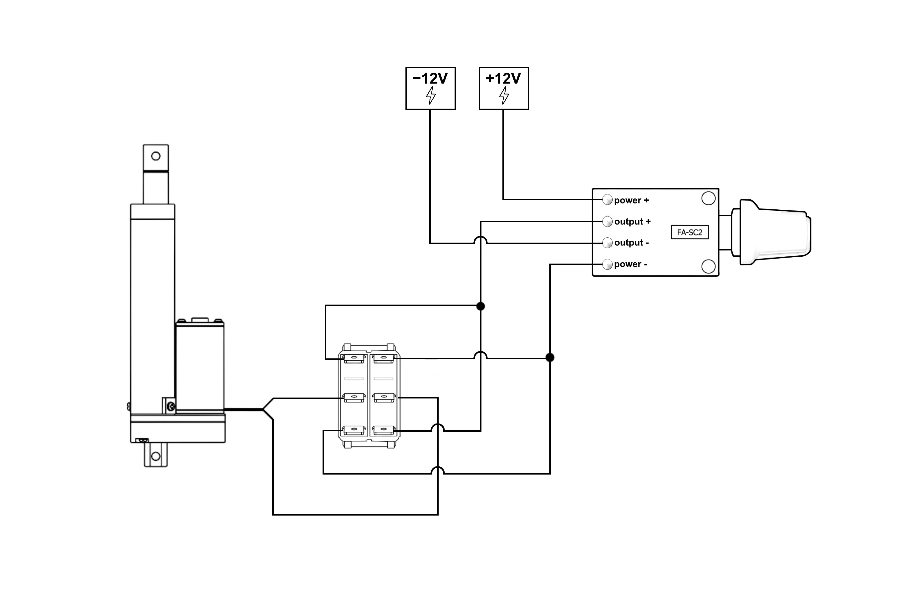
Standard Configuration with Rocker Switch
The most common setup incorporates a reversing switch (typically a DPDT rocker switch) to control direction, with the speed controller inline to regulate velocity. Here's the connection sequence:
- Power supply to switch: Connect your DC power supply's positive terminal to the center terminals of your DPDT switch. Connect the negative terminal to the common ground.
- Switch to speed controller: Wire one pole of the switch to the speed controller's input terminals. The switch reverses polarity to change actuator direction.
- Speed controller to actuator: Connect the speed controller's output terminals directly to your actuator's motor leads. Polarity matters here—if the actuator moves in the wrong direction, swap these connections.
- Ground connections: Ensure all ground/negative connections are properly tied together to prevent voltage potential differences that can cause erratic behavior.
Critical Electrical Specifications
Before connecting any speed controller, verify three key specifications:
- Voltage rating: Your speed controller must be rated for your system voltage, typically 12V or 24V for most actuator applications. Operating outside this range can damage the controller or create safety hazards.
- Current capacity: The controller must handle your actuator's maximum current draw, including the startup surge which can be 2-3x the running current. A 5-amp actuator should use a controller rated for at least 7-10 amps continuous with 15+ amp surge capacity.
- Duty cycle rating: Some inexpensive controllers are rated for intermittent use only. For applications requiring continuous operation, verify the controller supports 100% duty cycle at your required current level.
Using an undersized controller is one of the most common causes of premature failure. The controller may work initially but will overheat during extended use, eventually failing short-circuit (causing uncontrolled actuator movement) or open-circuit (leaving the actuator inoperable).
Understanding Feed-Forward Control for Predictable Performance
In control systems terminology, feed-forward control represents an open-loop approach where you predict the required controller output based on known system characteristics rather than continuously measuring actual performance. For linear actuators with simple PWM speed controllers, this is the standard operating mode—and for many applications, it's entirely sufficient.
When Open-Loop Speed Control Is Adequate
Feed-forward control assumes that once you've characterized your system (understanding the relationship between duty cycle and velocity under your specific load conditions), you can reliably predict performance. If you know that a 60% duty cycle produces approximately 25mm/second travel speed with your particular actuator and load, you can set the controller accordingly and expect consistent results—provided your load remains constant.
This approach works well for applications where:
- The load on the actuator is relatively constant and predictable
- Slight variations in speed (±10-15%) are acceptable
- Environmental factors (temperature, voltage fluctuations) are minimal
- You don't need synchronization between multiple actuators
- Cost and simplicity are priorities over absolute precision
Most hobbyist projects, furniture automation, and light-duty positioning applications fall into this category. A TV lift mechanism, for example, doesn't require millimeter-perfect positioning—users simply want smooth, quiet operation at a reasonable speed.
Limitations and When You Need Feedback
The fundamental limitation of feed-forward control is its inability to compensate for unexpected disturbances or varying loads. If your actuator encounters increased resistance mid-stroke, it will slow down but the controller won't automatically compensate. Similarly, if your power supply voltage drops under load, the actuator's actual speed will decrease even though the controller's duty cycle remains unchanged.
For applications requiring higher precision—medical equipment, synchronized multi-actuator systems, or positioning mechanisms where accuracy matters—a closed-loop feedback system becomes necessary. FIRGELLI's Actuator Control Board provides this capability by incorporating position and velocity feedback from feedback actuators equipped with Hall effect or optical sensors. The control system continuously compares desired versus actual performance and adjusts duty cycle in real-time to maintain target speeds regardless of load variations or environmental factors.
Key Advantages of Implementing Speed Control in Your Application
Adding a speed controller to your actuator system delivers benefits that extend beyond simply slowing things down. Understanding these advantages helps you make informed decisions about when speed control justifies the additional cost and complexity.
Enhanced Precision and Application Flexibility
The most obvious benefit is granular control over operating velocity. Different phases of your application may demand different speeds: rapid movement when positioning isn't critical, followed by slow, precise motion when approaching the target position. A standing desk mechanism might rise quickly to approximate height, then slow as it approaches your preset position to avoid overshooting. This two-stage approach optimizes both speed and accuracy.
Speed control also enables adaptation to varying load conditions. When your actuator is moving empty versus loaded, you might want different velocities to maintain consistent operating characteristics. This flexibility is particularly valuable in commercial applications where user preference matters—some users prefer fast operation, others prioritize quiet, smooth movement.
Reduced Mechanical Stress and Extended Service Life
Accelerating and decelerating gradually rather than abruptly reduces mechanical shock throughout your system. Every time an actuator starts or stops instantly at full speed, it generates impact forces that stress mounting points, gears, and mechanical connections. Over thousands of cycles, this accumulated stress manifests as loosened fasteners, worn mounting brackets, and premature component failure.
Implementing speed control with gradual ramp-up and ramp-down—easily achieved by slowly adjusting the controller during startup and shutdown—distributes these forces over time, dramatically reducing peak loads. This is particularly important for higher-force industrial actuators where the kinetic energy involved is substantial. A 500-pound-force actuator moving at full speed represents significant momentum; stopping it gradually rather than abruptly can extend system life by years.
Acoustic Benefits and Noise Management
Operating actuators at reduced speeds often significantly decreases audible noise. Motor noise is generally proportional to speed, and mechanical components vibrating at lower frequencies tend to be less perceptible. For applications in office environments, medical settings, or residential spaces, this noise reduction can be the difference between an acceptable and unacceptable installation.
Additionally, slower operating speeds reduce the amplitude of higher-frequency vibrations that tend to be most annoying to human ears. The whine of a micro linear actuator running at full speed might be objectionable, while the same actuator at 60% speed often operates nearly silently.
Multi-Actuator Synchronization
When your application requires multiple actuators to move in coordination—think adjustable platform legs, synchronized door openers, or multi-point lifting systems—speed control becomes essential. Even actuators from the same production batch exhibit slight performance variations due to manufacturing tolerances. Without speed control, one actuator might complete its stroke faster than its counterparts, creating binding, misalignment, or uneven loading.
By individually adjusting speed controllers on each actuator, you can ensure synchronized movement even with non-identical actuators. This is particularly valuable when mixing different actuator models or sizes within a single system. While sophisticated control box solutions offer programmable synchronization, simple speed controller adjustment often achieves adequate results for straightforward applications.
The High-Pitched Sound: Understanding PWM Acoustic Characteristics
One of the most common concerns when first using PWM speed controllers is the characteristic high-pitched whine or buzzing sound that emerges, particularly at certain speed settings. Understanding the source of this noise helps you determine whether it's normal operation or indicates a problem.
The Physics of PWM Audible Noise
The sound you're hearing originates from rapid electromagnetic field changes within your actuator's motor. As the PWM controller switches current on and off hundreds or thousands of times per second, the motor's internal coils expand and contract microscopically due to magnetostrictive forces—the tendency of ferromagnetic materials to slightly change shape in response to magnetic fields. When the PWM frequency or its harmonics fall within the human hearing range (approximately 20 Hz to 20 kHz), these vibrations become audible.
The pitch you hear corresponds to the controller's switching frequency or its harmonics. Many controllers operate between 500 Hz and 25 kHz; frequencies below about 8-10 kHz are most likely to be perceived as annoying because they fall within the range where human hearing is most sensitive. Higher frequencies (above 15-18 kHz) may be inaudible to many people, particularly as hearing sensitivity decreases with age.
Why the Sound Changes with Speed Settings
The noise is often most pronounced at intermediate speed settings (30-70% duty cycle) because this is where the switching is most "choppy"—neither predominantly on nor predominantly off. At very low or very high duty cycles, the noise may diminish because the motor coils spend most of their time in one state. Additionally, certain duty cycles may coincide with mechanical resonant frequencies of the motor assembly, amplifying vibrations at specific speed settings.
As you reduce speed (lower duty cycle), the motor receives less average power per switching cycle, which can paradoxically make the noise more apparent because there's less motor mechanical noise to mask it. The switching frequency itself typically remains constant, but the changing electromagnetic field pattern at different duty cycles alters the vibrational modes.
Is This Normal? Should You Be Concerned?
In most cases, this high-pitched sound is completely normal and doesn't indicate a problem with your controller or actuator. It's simply an acoustic byproduct of the PWM switching process. However, if the sound is excessively loud, changes dramatically over time, or is accompanied by reduced performance or excessive heat, it might indicate:
- An undersized controller operating near its current limit
- Poor electrical connections creating resistance and arcing
- A controller operating at an unfortunate frequency that creates resonance
- Worn motor brushes (in brushed DC motors) creating irregular current draw
If the noise is objectionable but the system is functioning correctly, you can try several mitigation strategies: operate at different speed settings where resonance is less pronounced, add dampening material around the actuator mounting, or switch to a higher-frequency PWM controller where the switching frequency exceeds the human hearing range. Some premium controllers offer adjustable PWM frequency specifically to address acoustic concerns.

Selecting the Right Speed Controller for Your Application
Not all PWM speed controllers are created equal. While the fundamental operating principle remains consistent, implementation details significantly affect performance, reliability, and suitability for different applications. Understanding these differences helps you choose appropriately rather than defaulting to the cheapest available option.
Matching Electrical Specifications to Your Actuator
The first and most critical specification is current-handling capacity. Your controller must be rated for both the continuous current your actuator draws during normal operation and the surge current during startup. Actuators with higher force ratings and longer strokes typically draw more current. A conservative approach is to select a controller rated for at least 150% of your actuator's maximum continuous current draw.
Voltage rating is equally important. Most actuator applications operate at 12V or 24V DC, but some industrial actuators may require 36V or 48V. Using a controller rated for a different voltage can result in either inadequate performance or component damage. If your application might see voltage fluctuations (common in automotive or solar-powered installations), ensure your controller includes overvoltage protection.
Essential Features and Optional Enhancements
Basic PWM controllers offer simple speed adjustment via a potentiometer dial—adequate for most applications. More sophisticated controllers may include:
- Soft-start capability: Automatically ramps up duty cycle gradually at startup to reduce mechanical shock
- Adjustable PWM frequency: Allows you to tune the switching frequency to minimize audible noise
- Thermal protection: Automatically reduces output or shuts down if the controller overheats
- Reverse polarity protection: Prevents damage if power connections are accidentally reversed
- Remote control input: Accepts external voltage signal for programmable speed control via microcontroller or PLC
For more demanding applications, consider closed-loop controllers that accept feedback from feedback actuators. These maintain precise speed control even under varying loads by continuously adjusting duty cycle based on actual measured performance rather than relying on the feed-forward approach of simple PWM controllers.
Build Quality and Reliability Factors
The internal components and construction quality of speed controllers vary dramatically across price points. Inexpensive controllers may use minimal heatsinking, lower-grade MOSFETs with higher on-resistance (generating more heat), and lack protective features. While these can work adequately for intermittent use in non-critical applications, they're prone to failure under sustained loads or adverse conditions.
Higher-quality controllers feature robust heatsinking (often with finned aluminum housings), oversized components for reliable operation, and comprehensive protection circuitry. For commercial applications or installations where failure creates significant problems (inaccessible locations, safety-critical systems, or expensive assemblies), the additional cost of a premium controller is almost always justified by improved reliability and longevity.
Integration with Control Systems and Automation
While manual speed control via a potentiometer dial suits many applications, integrating your actuator into a broader automation system opens new possibilities for sophisticated motion control. Understanding your integration options helps you design systems that grow with your needs.
Arduino and Microcontroller-Based Control
Many hobbyists and developers use Arduino or similar microcontrollers to create custom actuator control systems. Standard PWM speed controllers designed for manual operation typically can't interface directly with microcontrollers—they expect DC input voltage rather than logic-level signals. However, by selecting controllers with analog voltage input capability (0-5V or 0-10V control signal inputs), you can use a microcontroller's digital-to-analog converter (DAC) or PWM output filtered through a low-pass RC circuit to generate the control voltage.
Alternatively, dedicated motor driver modules designed for microcontroller applications (H-bridge motor drivers with PWM inputs) can be used directly with actuators, though these typically lack the current capacity for larger actuators and require additional circuitry for current amplification. For applications requiring multiple actuators or complex motion sequences, a microcontroller-based approach with appropriate motor drivers provides enormous flexibility at reasonable cost.
Closed-Loop Position and Velocity Control
For applications demanding precision that open-loop speed control cannot deliver, implementing feedback-based closed-loop control becomes necessary. FIRGELLI's Actuator Control Board provides this capability by accepting input from feedback actuators equipped with Hall effect sensors or optical encoders. These sensors provide real-time position and velocity data, enabling the control board to continuously adjust motor drive to maintain target speeds regardless of load variations, voltage fluctuations, or environmental factors.
The distinction between open-loop and closed-loop control is particularly important for multi-actuator synchronization, positioning applications requiring repeatability within ±1mm or better, and systems where external forces on the actuator vary unpredictably. Medical equipment, precision positioning stages, and automated testing fixtures typically require closed-loop control for reliable operation.
Wireless and Remote Control Options
For applications where manual wired control isn't practical, remote control systems allow wireless operation of your actuator system. Simple on-off remote controls can be combined with your speed controller for wireless speed-adjusted operation. More sophisticated remote systems include speed control integrated into the remote itself, allowing adjustment of both direction and velocity wirelessly.
When integrating remote controls with speed controllers, pay attention to the control system's current capacity—ensure both the remote control receiver and the speed controller are rated for your actuator's current draw. In some configurations, the remote control handles only the switching logic while a separate speed controller handles the actual motor current, providing both wireless convenience and proper speed control.
Conclusion: Making Speed Control Work for Your Application
Implementing speed control for your linear actuator application is one of the most cost-effective upgrades you can make, dramatically improving system performance, mechanical longevity, and user experience. Whether you're building a custom automation project, upgrading existing equipment, or designing commercial products, understanding the principles behind PWM speed control enables you to make informed decisions about controller selection and implementation.
The key is matching your speed control approach to your application's actual requirements. Simple open-loop PWM controllers suit the vast majority of hobbyist and light commercial applications where approximate speed control and cost-effectiveness are priorities. For applications demanding precision, repeatability, or multi-actuator synchronization, investing in closed-loop control systems with position and velocity feedback delivers the performance necessary for reliable operation.
As you implement speed control in your projects, remember that proper electrical sizing, quality wiring practices, and realistic performance expectations are just as important as selecting the right controller. Take time to characterize your system's behavior at different speed settings under actual operating conditions—the relationship between duty cycle and velocity isn't perfectly linear, and understanding your specific system's characteristics enables you to predict and optimize performance effectively.
Frequently Asked Questions
Can I use a PWM speed controller with any linear actuator?
Most standard DC linear actuators are compatible with PWM speed controllers, but there are important considerations. The controller must be rated for your actuator's voltage (typically 12V or 24V) and current draw, including startup surge current which can be 2-3 times the running current. Actuators with integrated limit switches or position feedback sensors work fine with simple PWM controllers, though closed-loop controllers specifically designed for feedback actuators offer enhanced precision. Very small micro linear actuators drawing under 1 amp may not work well with controllers designed for higher currents, as these often have minimum load requirements. Always verify that your controller's current capacity exceeds your actuator's maximum draw by at least 50% for reliable operation.
Will using a speed controller allow my actuator to move slower than its rated speed?
Yes, PWM speed controllers can reduce actuator speed to a fraction of rated velocity, typically down to approximately 20-30% of maximum speed before performance becomes unreliable. Below this threshold, the motor may stall under load or exhibit jerky movement because it's receiving insufficient power to overcome static friction and maintain smooth motion. The minimum achievable speed depends on your actuator's internal motor characteristics, the load it's moving, and the quality of your speed controller. Higher-quality actuators with better motor designs typically maintain smoother operation at lower speeds. For applications requiring very slow, precise motion, consider using a lower-speed actuator with appropriate gearing rather than running a high-speed actuator at very low duty cycles, as this provides more torque and more reliable slow-speed performance.
Does using a speed controller reduce power consumption?
Yes, operating an actuator at reduced speeds through a PWM controller does reduce average power consumption proportional to the speed reduction. An actuator running at 50% duty cycle (roughly half speed) consumes approximately 50% of the power it would draw at full speed. However, the relationship isn't perfectly linear due to motor efficiency characteristics and fixed parasitic losses. The practical energy savings depend heavily on your duty cycle—applications that spend most of their time moving slowly save considerably, while those that only occasionally need reduced speed see minimal savings. It's worth noting that the energy saved in the motor is actual reduction in power draw from your supply, not just energy dissipated as heat like with resistive speed control methods. This makes PWM speed control particularly valuable for battery-powered applications where extended runtime matters.
Can I control multiple actuators with one speed controller?
Technically yes, you can wire multiple actuators in parallel and control them with a single speed controller, but this approach has significant limitations and is generally not recommended except for very specific applications. The primary issue is that the controller must be rated for the combined current draw of all actuators, and any performance differences between actuators (due to manufacturing variations, load differences, or wear) will cause them to move at different speeds despite receiving the same power. This creates synchronization problems and uneven loading. For applications requiring multiple actuators to move in coordination, it's far better to use individual speed controllers for each actuator, allowing you to fine-tune each one for synchronized movement. Alternatively, dedicated multi-channel control box systems designed for synchronized actuator operation provide proper coordination through feedback-based control. If you do parallel multiple actuators on one controller, ensure they're from the same production batch with identical specifications and similar loading conditions for best results.
Is it normal for my speed controller to get warm during operation?
Yes, some warmth is completely normal during operation, as even efficient PWM controllers generate heat during switching transitions. However, there's a significant difference between "warm to the touch" and "too hot to hold." A properly sized controller operating within its specifications should reach a stable temperature that's noticeably warm but not uncomfortably hot after several minutes of continuous operation. If your controller becomes extremely hot (60°C/140°F or higher), it likely indicates undersizing—the controller isn't rated for adequate current capacity for your application. This is particularly common when users forget to account for startup surge current, which can be double or triple the running current. Excessive heat accelerates component degradation and will eventually lead to premature failure. If your controller is running very hot, immediately upgrade to a higher-capacity unit or reduce your duty cycle to lower the average current draw. For continuous-duty applications, ensure your controller is rated for 100% duty cycle at your required current level, and provide adequate airflow around the controller for cooling. Adding a small heatsink or cooling fan can extend controller life in demanding applications.


