Electric reclining beds represent a significant advancement in sleep technology and home comfort, transforming the simple act of rest into a customizable, therapeutic experience. Whether you're managing chronic back pain, recovering from surgery, improving circulation, or simply seeking the ultimate in sleeping comfort, understanding the engineering and technology behind these beds is essential for making informed decisions. This comprehensive guide explores the motion control systems, actuator selection, design principles, and practical considerations that make electric reclining beds both a medical necessity and a luxury worth investing in.
The technology that enables smooth, reliable bed adjustment has evolved dramatically over the past two decades. Modern electric reclining beds rely on sophisticated linear actuators rather than traditional hydraulic systems, offering quieter operation, greater precision, and significantly improved reliability. For engineers, DIY builders, and consumers alike, understanding how these systems work—from force calculations to actuator selection—provides the foundation for choosing, building, or troubleshooting an electric reclining bed that will deliver years of dependable service.

How Electric Reclining Beds Work: Understanding the Motion Control System
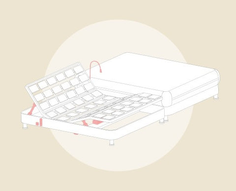
At the heart of every electric reclining bed is a motion control system that coordinates multiple actuators to adjust different sections of the bed independently or in concert. Unlike manual beds that rely on springs and latches, electric beds use precision motor-driven actuators controlled by microprocessor-based systems that ensure smooth, synchronized movement across all articulation points.
The motion control architecture typically consists of several key components working in harmony. The controller—whether a simple wired handset or a sophisticated wireless remote control—sends signals to a control box that processes user inputs and distributes appropriate voltage to each actuator. Advanced systems may include position memory, allowing users to save preferred configurations and return to them with a single button press.
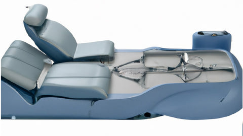
Most electric reclining beds feature three to five adjustment zones: head elevation, lumbar support, knee raise, foot elevation, and sometimes full-bed tilt (Trendelenburg/reverse Trendelenburg positioning). Each zone requires its own actuator with appropriate stroke length and force capacity. The control system must coordinate these movements to prevent binding, ensure smooth transitions, and maintain structural integrity throughout the range of motion.
Modern control systems incorporate several safety features that prevent damage and ensure user safety. Overload protection stops actuator movement when encountering obstacles or excessive resistance. Anti-collision logic prevents zones from moving into positions that would create mechanical interference. Soft-start and soft-stop ramping prevents sudden jerks that could disturb sleep or cause discomfort. These features require sophisticated programming but are essential for reliable, long-term operation.
Linear Actuators: The Muscle Behind Adjustable Beds
Linear actuators serve as the fundamental motion components in electric reclining beds, converting electrical energy into linear mechanical motion. Understanding actuator construction, specifications, and selection criteria is critical for anyone designing, building, or upgrading an adjustable bed system.
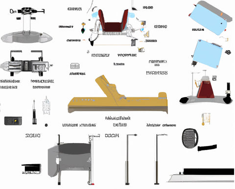
Actuator Construction and Types
Electric linear actuators for bed applications typically feature a DC motor coupled to a lead screw or ball screw mechanism through a precision gearbox. The motor provides rotational force, the gearbox reduces speed while increasing torque, and the screw mechanism converts rotation into linear motion. The entire assembly is housed in a protective tube or casing that shields internal components from dust and debris.
For bed applications, linear actuators must balance several competing requirements: sufficient force capacity (typically 200-500 lbs per actuator), moderate speed (0.5-1.0 inches per second), reasonable stroke length (8-16 inches depending on zone), low noise operation (under 50 dB), and duty cycle appropriate for residential use. Industrial actuators designed for continuous operation may be oversized and costly for bed applications, while lighter-duty actuators may fail prematurely under regular use.
Some advanced bed systems incorporate feedback actuators equipped with Hall effect sensors or potentiometers that provide position information to the control system. This feedback enables precise positioning, synchronization between multiple actuators, and memory functions that allow users to save and recall preferred positions. While more expensive than standard actuators, feedback-equipped models significantly enhance functionality and user experience.
Force and Speed Specifications
Actuator force capacity, measured in pounds or newtons, must exceed the maximum load that will be applied throughout the range of motion. For head and foot sections of a typical bed, 200-300 lbs of force per actuator generally suffices for single or queen-size beds. Heavier users or king-size beds may require 400-500 lb actuators, particularly for the center support area that bears the greatest load.
Speed specifications determine how quickly the bed transitions between positions. While faster movement (1.0-1.5 inches per second) seems desirable, moderate speeds (0.5-0.8 inches per second) actually provide better user experience by eliminating sudden motion that could disturb sleep or cause alarm. Additionally, slower speeds reduce mechanical stress on the frame, extend actuator life, and operate more quietly—critical considerations for bedroom furniture.
The relationship between force and speed follows an inverse relationship due to the gearbox ratio. Higher force capacity requires greater gear reduction, which reduces output speed. This trade-off means designers must carefully match actuator specifications to application requirements rather than simply choosing the highest specifications available.
Engineering Considerations and Force Calculations
Proper actuator selection requires understanding the forces involved in bed articulation and applying appropriate safety factors to ensure reliable operation. Unlike simple lifting applications, adjustable beds involve complex loading scenarios that vary throughout the range of motion.
Understanding Load Dynamics
The forces acting on bed actuators include the weight of the bed section being lifted, the weight of the mattress, the weight of the user (distributed across multiple sections), and friction forces from hinges and bearings. As the bed section tilts from horizontal toward vertical, the component of weight that must be lifted decreases according to the sine of the angle, but leverage disadvantages at certain mounting positions can increase required force.
The formula for calculating basic lifting force is: Force = (Total Weight × sin(Angle)) / Mechanical Advantage, where total weight includes the bed frame section, mattress portion, and user weight distribution, angle is measured from horizontal, and mechanical advantage depends on actuator mounting geometry. However, this simplified calculation doesn't account for friction, which can add 15-25% to the required force depending on hinge quality and bearing type.
A proper engineering analysis also considers dynamic loads during motion. When the actuator starts or stops, inertial forces momentarily increase the load beyond static calculations. Similarly, if a user shifts position during bed adjustment, instantaneous load spikes can occur. These considerations justify applying safety factors of 1.5 to 2.0 times the calculated static force requirement.
Practical Force Calculation Example
Consider a queen-size bed head section supporting 80 lbs of frame weight, 30 lbs of mattress, and 120 lbs of user upper body weight (total 230 lbs). To lift this section to 45 degrees with the actuator mounted 24 inches from the pivot and attached to the lifting frame 30 inches from the pivot, the required force calculation proceeds as follows:
First, determine the load component at maximum angle: 230 lbs × sin(45°) = 163 lbs. Next, account for mechanical disadvantage: 163 lbs × (30/24) = 204 lbs. Add 20% for friction: 204 lbs × 1.20 = 245 lbs. Finally, apply 1.5 safety factor: 245 lbs × 1.5 = 368 lbs. This analysis indicates a 400 lb actuator would be appropriate for this application, providing adequate capacity with reasonable safety margin.
For multiple actuator installations, the total load should be divided equally among actuators, though in practice, manufacturing tolerances and mounting variations mean actuators rarely share loads perfectly. This reality reinforces the importance of adequate safety factors in the specification process.
Selecting the Right Actuators for Your Electric Bed Project
Choosing appropriate actuators involves more than force calculations—stroke length, voltage, mounting style, environmental protection, and duty cycle all influence long-term performance and user satisfaction. Understanding these parameters helps both DIY builders and commercial manufacturers make informed decisions.
Stroke Length Requirements
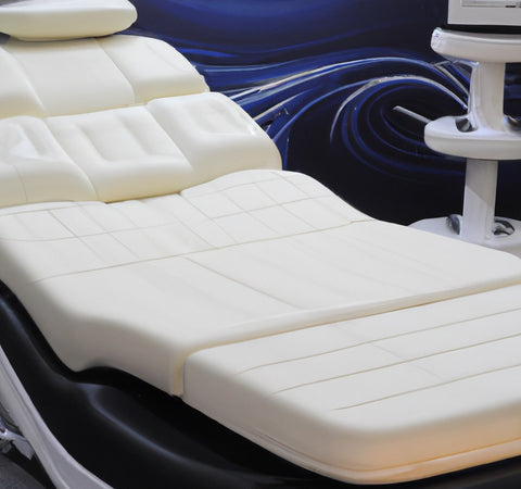
Stroke length—the total distance the actuator can extend—determines the maximum range of motion for each bed section. Head sections typically require 8-12 inches of stroke to achieve 60-70 degrees of elevation from horizontal. Foot sections need 6-10 inches for comfortable knee and leg elevation. Longer strokes provide more adjustment range but increase collapsed length, potentially complicating mounting and reducing ground clearance.
When determining required stroke length, consider the mounting geometry carefully. Actuators mounted closer to the pivot point require less stroke to achieve the same angular range, but they also require higher force capacity due to leverage disadvantage. Conversely, actuators mounted farther from the pivot need longer stroke but can operate with lower force ratings. This trade-off allows designers some flexibility in optimizing actuator selection for specific frame designs.
Voltage and Power Considerations
Most residential electric beds operate on 12V or 24V DC power supplied by plug-in transformers. The 12V standard offers advantages in terms of safety, component availability, and compatibility with automotive and marine parts suppliers. However, 24V systems can deliver the same power at half the current, reducing wire gauge requirements and minimizing voltage drop in longer cable runs—potentially important in king-size beds with multiple actuators.
Appropriate power supplies must provide sufficient current capacity for simultaneous actuator operation. A typical 12V actuator under load draws 3-5 amps, meaning a bed with four actuators could draw 20 amps if all actuators operate simultaneously. Quality power supplies with 25-30 amp capacity ensure reliable operation without overheating or voltage sag. Using undersized power supplies leads to slow actuator speed, overheating, and premature failure.
Mounting Brackets and Installation Hardware
Reliable actuator mounting requires purpose-designed mounting brackets that prevent side-loading while allowing free rotation at both actuator ends. Side loads—forces perpendicular to the actuator shaft—dramatically accelerate wear on internal bushings and can cause premature failure. Proper mounting uses clevis or spherical bearings that maintain alignment throughout the range of motion.
The mounting hardware must also resist the full actuator force without deflection or failure. For a 400 lb actuator, the mounting points, fasteners, and frame structure must all withstand this load with appropriate safety factors. In wooden frames, this typically requires through-bolting with large washers or backing plates to distribute loads. Metal frames should use grade 5 or better bolts with appropriate thread engagement and lockwashers to prevent loosening from vibration.
Building an Electric Reclining Bed: Step-by-Step Process
Constructing a custom electric reclining bed allows precise tailoring to individual needs and preferences while often reducing costs compared to commercial models. However, successful builds require careful planning, appropriate materials, and methodical execution to ensure safety and durability.
Frame Design and Construction
The bed frame provides structural support for the mattress, user, and articulation mechanism. Most DIY designs use dimensional lumber (2x4, 2x6) or steel tubing for main rails, with plywood decking to support the mattress. The frame must be divided into articulating sections—typically head, center, thigh, and foot—connected by heavy-duty hinges that align precisely to prevent binding during motion.
Critical design considerations include hinge placement (which determines articulation points), actuator mounting locations (which affect force requirements and stroke length), and overall structural rigidity. The frame must resist twisting and flexing under load while remaining light enough for the actuators to move smoothly. Cross-bracing, gusset plates, and proper joint design all contribute to frame strength without excessive weight.
For wooden frames, use moisture-resistant materials like birch plywood or marine-grade lumber to prevent warping from humidity. Apply protective finishes to exposed wood surfaces. Metal frames should use mild steel tubing with welded or bolted joints, properly primed and painted to prevent rust. All pivot points should incorporate proper bearings or bushings—never allow wood-to-wood or metal-to-metal contact that will wear rapidly and create noise.
Actuator Installation and Wiring
Begin actuator installation by mounting fixed brackets to the bed base using appropriate fasteners for your frame material. Position the actuator at its mid-stroke position and mark the mounting location on the articulating frame section, ensuring alignment prevents side-loading. Install the moving bracket using through-bolts with lock washers—never rely on wood screws alone for actuator mounting points under load.
Electrical wiring should follow best practices for low-voltage DC systems. Use wire gauges appropriate for the current and length—typically 16 AWG minimum for runs under 10 feet, 14 AWG for longer distances. Route wires away from moving parts and sharp edges, using cable management clips or conduit where appropriate. All connections should use quality crimp connectors or soldered joints with heat shrink tubing—never twist wires together or use wire nuts for permanent installations.
The control system installation varies depending on whether you're using a simple switch box, a multi-function remote control, or a sophisticated control box with memory functions. Follow the manufacturer's wiring diagram precisely, paying attention to polarity and ensuring all actuators move in the correct direction. Test each zone independently before connecting the complete system, verifying smooth operation throughout the full range of motion.
Testing and Adjustment
Once assembly is complete, conduct thorough testing before regular use. Operate each zone through its full range multiple times, listening for unusual noises, binding, or irregular motion. Check all fasteners for tightness after initial operation—some settling and adjustment is normal. Verify that safety features like overload protection function correctly by deliberately creating resistance during motion.
Fine-tuning may involve adjusting actuator mounting positions slightly to optimize motion, modifying end-of-travel limits to prevent over-extension, or adjusting control system parameters for desired speed and smoothness. Document all settings and specifications for future reference and maintenance. Take photographs of the wiring and mounting arrangements before covering them with mattress and bedding—these will prove invaluable if troubleshooting becomes necessary later.
Maintenance and Troubleshooting Common Issues
Electric reclining beds require minimal maintenance when properly designed and built, but periodic inspection and basic care extend service life and ensure continued reliable operation. Understanding common failure modes helps identify problems early before they cause major damage or safety hazards.
Routine Maintenance Procedures
Every six months, conduct a basic inspection of all mechanical and electrical components. Check mounting bolts and fasteners for tightness, retightening as necessary. Inspect actuator mounting points for signs of wear, cracking, or deflection. Verify that hinges rotate smoothly without binding or excessive play. Listen for unusual noises during operation—squeaks, grinding, or clicking often indicate developing problems.
Clean exposed actuator rods periodically with a soft cloth dampened with light machine oil to remove dust and prevent corrosion. Never use harsh solvents or abrasive cleaners that could damage protective coatings. Check electrical connections for corrosion or looseness, particularly in humid environments. Inspect power cords for damage and ensure the power supply ventilation remains unobstructed.
Common Problems and Solutions
If an actuator moves slowly or struggles under load, possible causes include insufficient power supply capacity, worn internal gears, or excessive friction in the mounting hardware. Verify the power supply provides adequate voltage under load (should remain above 11V for 12V systems). Check that mounting brackets allow free rotation without side-loading. If the actuator itself is faulty, replacement is usually more cost-effective than repair.
Uneven motion between multiple actuators often results from voltage drop in undersized wiring or corroded connections. Use a multimeter to verify equal voltage at each actuator during operation. If one actuator receives significantly less voltage, check connections and wire gauge. For systems with feedback actuators, calibration may be required if position synchronization drifts over time—consult the control system documentation for calibration procedures.
Complete actuator failure typically presents as no motion despite control inputs and adequate power. First, verify power reaches the actuator by measuring voltage at the actuator terminals during operation. If voltage is present but the actuator doesn't move, internal motor or gear failure has likely occurred. If no voltage reaches the actuator, the problem lies in the control system, wiring, or power supply. Systematic troubleshooting from power source to actuator will isolate the fault.
Comparing Electric Actuators to Alternative Technologies
While modern electric beds overwhelmingly use DC electric linear actuators, understanding alternative technologies provides context for appreciating electric actuation advantages and recognizing situations where alternatives might be appropriate.
Hydraulic Systems
Hydraulic cylinders can provide enormous force capacity in compact packages, making them suitable for heavy-duty medical beds or applications requiring lifting of extreme loads. However, hydraulics require pumps, reservoirs, hoses, and valves that add complexity, weight, and potential leak points. Noise from hydraulic pumps exceeds electric actuators significantly, and the environmental concerns about hydraulic fluid (plus the mess from inevitable leaks) make hydraulics impractical for residential furniture applications.
Pneumatic Systems
Pneumatic cylinders offer rapid motion and simple control, but they require compressed air sources—either dedicated compressors or connection to existing air systems. For residential beds, the requirement for a compressor eliminates any practical advantage. Pneumatics find application in hospital and institutional settings where compressed air is already available, but even there, electric actuation has largely replaced pneumatics due to superior position control and quieter operation.
Manual Mechanisms
Manual adjustment using cranks, levers, or gas springs costs less initially but requires physical effort that defeats the purpose of an adjustable bed for many users with mobility limitations or health conditions. Manual mechanisms also lack the precise positioning, memory functions, and convenience that make electric beds genuinely therapeutic rather than merely adjustable. For DIY builders on tight budgets, manual adjustment represents a compromise, but the modest cost of quality electric actuators makes this compromise rarely worthwhile.
Frequently Asked Questions
What size linear actuator do I need for an electric reclining bed?
For a typical queen-size bed, actuators with 200-300 lb force capacity, 8-12 inch stroke length, and 0.5-0.8 inch/second speed work well for head and foot sections. Larger beds or heavier users may require 400-500 lb actuators. Always perform force calculations based on your specific design, including bed section weight, mattress weight, and user weight distribution. Apply a safety factor of 1.5-2.0 to your calculated forces to ensure reliable long-term operation.
How many actuators does an electric bed need?
Most electric reclining beds use two to four actuators depending on the number of adjustment zones. A basic split design uses two actuators (head and foot). Three-actuator designs add independent thigh support. Four-actuator designs provide separate control for upper and lower leg sections or dual operation for king-size beds. Each adjustment zone requires its own actuator, and wider beds may need paired actuators (two per zone) for even lifting and weight distribution.
Should I use 12V or 24V actuators for my bed project?
For most DIY bed projects, 12V actuators offer the best balance of safety, component availability, and performance. The 12V standard provides adequate power for residential bed applications while remaining inherently safer due to lower voltage. However, 24V systems become advantageous for king-size beds with long cable runs or multiple actuators, as they reduce current requirements and minimize voltage drop. Either voltage works reliably when properly implemented with appropriately sized wiring and power supplies.
How quiet are electric reclining beds with linear actuators?
Quality electric linear actuators designed for furniture applications typically operate at 45-50 dB—roughly equivalent to quiet conversation or a modern refrigerator. This noise level is generally not disturbing during sleep adjustments. Poorly designed or worn actuators, inadequate mounting that allows vibration transmission, or undersized power supplies that cause laboring can all increase noise significantly. Proper installation with quality components ensures acceptably quiet operation.
What is the maximum weight capacity for an electric reclining bed?
Weight capacity depends on frame construction, actuator specifications, and the number of actuators rather than the actuation system itself. A properly engineered bed frame with appropriately sized actuators can support 500-1000 lbs or more. Standard residential designs typically accommodate 400-600 lbs comfortably. For bariatric applications requiring higher capacity, use stronger frame materials, additional support points, higher-capacity actuators (500-750 lbs each), and possibly more actuators to distribute loads evenly.
How much electricity does an electric reclining bed use?
Electric beds consume minimal power during actual operation—typically 50-150 watts while actuators are moving. However, actuators only run for seconds at a time during position changes, so actual energy consumption is negligible. The control system and transformer draw small standby power (typically 1-5 watts) continuously when plugged in. Annual electricity cost for normal use ranges from $2-5—far less than most household appliances. There is no practical reason to unplug the bed when not in use except during extended absences.
How long do electric bed actuators last?
Quality linear actuators designed for furniture applications typically provide 10,000-50,000 cycles of operation before wear becomes significant. For a bed adjusted twice daily, this represents 15-70 years of service. However, actuator lifespan depends heavily on proper installation, appropriate force rating for the application, and operating conditions. Overloaded actuators, side-loading from improper mounting, or operation in humid environments without adequate protection all reduce service life significantly. Properly specified and installed actuators commonly outlast the bed frame itself.
How difficult is it to build your own electric reclining bed?
Building a custom electric bed requires intermediate to advanced DIY skills including woodworking or metalworking, basic electrical wiring, and mechanical assembly. The project typically takes 20-40 hours spread over several days. Success depends on careful planning, accurate force calculations for actuator selection, precise frame construction to prevent binding, and methodical electrical installation. Individuals comfortable with projects like building furniture, installing home automation, or automotive modifications generally possess the necessary skills. Complete beginners should consider simpler projects first to develop relevant capabilities.


