Designing an antenna, selecting a fiber optic wavelength, or analyzing a photon's energy all start with the same problem: relating wave speed, frequency, and spatial period to something physically meaningful. Use this Wavelength Interactive Calculator to calculate wavelength, frequency, wave speed, or photon energy using inputs you already know. It covers the full electromagnetic spectrum and mechanical wave regimes — critical for RF communications, optical engineering, acoustic system design, and quantum physics. This page includes the core formulas, a worked antenna design example, theory across multiple wave regimes, and a detailed FAQ.
What is wavelength?
Wavelength is the distance a wave travels to complete one full cycle — the gap between two identical points on a repeating wave, such as crest to crest. The shorter the wavelength, the higher the frequency; the longer the wavelength, the lower the frequency.
Simple Explanation
Think of dropping a stone into still water and watching the ripples spread outward. The distance between two adjacent ripple peaks is the wavelength. For any wave — sound, light, radio — that gap depends on how fast the wave travels and how many cycles it completes per second. Fast wave, low frequency? Long wavelength. Fast wave, high frequency? Short wavelength.
📐 Browse all 1000+ Interactive Calculators
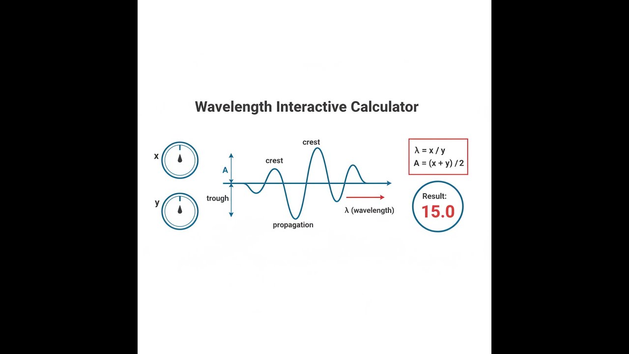
Wave Diagram

How to Use This Calculator
- Select your calculation mode from the dropdown — choose what you want to solve for (wavelength, frequency, wave speed, or photon energy).
- Enter the known values into the visible input fields, such as frequency in Hz or wavelength in meters. The wave speed defaults to the speed of light — change it for acoustic or other mechanical waves.
- If calculating photon energy or wavelength from energy, select the correct energy unit (Joules or electron volts).
- Click Calculate to see your result.
Interactive Wavelength Calculator
Wavelength Interactive Visualizer
Visualize how frequency, wavelength, and wave speed relate across the electromagnetic spectrum. Adjust parameters to see real-time wave animation and calculate photon energy for any wavelength.
WAVELENGTH
600 nm
PHOTON ENERGY
2.07 eV
SPECTRUM
Visible
FIRGELLI Automations — Interactive Engineering Calculators
Fundamental Equations
Use the formula below to calculate wavelength, frequency, or wave speed.
Wave Equation
v = f λ
λ = v / f
f = v / λ
Use the formula below to calculate photon energy from wavelength.
Photon Energy (Planck-Einstein Relation)
E = h f = h c / λ
λ = h c / E
Use the formula below to calculate derived wave parameters including period, wave number, and angular frequency.
Derived Wave Parameters
T = 1 / f (period)
k = 2π / λ (wave number)
ω = 2π f (angular frequency)
Variable Definitions:
- λ (lambda) = Wavelength (m)
- f = Frequency (Hz or s-1)
- v = Wave propagation speed (m/s)
- c = Speed of light in vacuum = 299,792,458 m/s
- E = Photon energy (J or eV)
- h = Planck's constant = 6.626 × 10⁻³⁴ J·s
- T = Period (s)
- k = Wave number (m-1 or rad/m)
- ω (omega) = Angular frequency (rad/s)
Simple Example
A green light source emits at a frequency of 5 × 10¹⁴ Hz. Wave speed = 3 × 10⁸ m/s (speed of light).
λ = v / f = 3 × 10⁸ / 5 × 1014 = 6 × 10⁻⁷ m = 600 nm
Result: 600 nm — visible green light, as expected.
Theory & Practical Applications
Physical Basis of Wavelength
Wavelength represents the spatial periodicity of a wave—the distance between successive points of identical phase. For electromagnetic radiation, wavelength and frequency maintain an inverse relationship governed by the constant speed of light in vacuum, making wavelength determination fundamental to spectroscopy, telecommunications, and quantum optics. The wave equation v = f λ applies universally to mechanical waves (sound, seismic, water) and electromagnetic radiation, though the physical mechanisms differ profoundly. In mechanical systems, wave speed depends on medium properties: tension and linear density for strings (v = √(T/μ)), bulk modulus and density for gases (v = √(B/ρ)). In electromagnetic systems operating in vacuum, c is invariant, making wavelength and frequency interchangeable specifications of the same physical phenomenon.
A critical engineering distinction often overlooked: the relationship v = f λ provides phase velocity, not group velocity. In dispersive media—where wave speed varies with frequency—individual wave crests travel at phase velocity while energy and information propagate at group velocity vg = dω/dk. Optical fiber communications exploit this difference: while 1550 nm telecom signals maintain constant λ in vacuum, chromatic dispersion in silica fiber causes different wavelength components to travel at different group velocities, limiting maximum bit rate over distance. Engineers specify fiber dispersion in ps/(nm·km), quantifying pulse broadening per nanometer of spectral width per kilometer of propagation.
Electromagnetic Spectrum Engineering
The electromagnetic spectrum spans over 20 orders of magnitude in wavelength, each regime governed by different interaction physics and requiring distinct engineering approaches. Radio frequencies (λ > 1 mm, f < 300 GHz) enable wireless communications because long wavelengths diffract around obstacles and penetrate buildings—Rayleigh scattering losses scale as λ-4, making VHF/UHF superior for mobile coverage despite lower data capacity. The 2.4 GHz Wi-Fi band (λ = 12.5 cm) represents a compromise: short enough for manageable antenna sizes, long enough to penetrate walls with acceptable attenuation.
Infrared wavelengths (700 nm to 1 mm) dominate thermal imaging and fiber optic telecommunications. The atmospheric transmission windows at 3-5 μm and 8-14 μm dictate LWIR and MWIR thermal camera design—water vapor absorption is minimal at these wavelengths, enabling long-range thermal surveillance. Telecom engineers exploit the low-loss window in silica fiber at 1550 nm (0.2 dB/km attenuation) rather than the zero-dispersion wavelength at 1310 nm, accepting dispersion compensation complexity to maximize transmission distance.
Visible light (400-700 nm) represents less than one octave of the electromagnetic spectrum yet drives photosynthesis, human vision, and display technology. The peak solar spectral irradiance at 500 nm (green) explains why silicon solar cells—with bandgap energy corresponding to 1100 nm—cannot achieve theoretical maximum efficiency: much of the solar spectrum energy exceeds the bandgap, with excess photon energy lost as heat. UV wavelengths below 400 nm enable photolithography for semiconductor manufacturing—193 nm ArF excimer lasers currently define leading-edge chip production, with EUV at 13.5 nm pushing Moore's Law continuation.
Quantum Mechanics and Photon Energy
The Planck-Einstein relation E = hf = hc/λ fundamentally links wavelength to photon energy, critical for photoelectric effect calculations, photochemistry, and semiconductor device physics. A photon's energy determines whether it can excite electronic transitions, ionize atoms, or break chemical bonds. X-ray wavelengths around 0.1 nm (12.4 keV photons) exceed most atomic binding energies, enabling medical imaging and crystallography. The relationship is nonlinear in practical units: E(eV) = 1239.8 / λ(nm), meaning doubling wavelength halves photon energy.
Semiconductor bandgap engineering exploits this relationship precisely. LED emission wavelength is determined by bandgap energy: Eg = hc/λpeak. Gallium nitride (Eg = 3.4 eV) emits at 365 nm (UV), while indium gallium nitride alloys enable tuning across the visible spectrum by varying indium fraction. The efficiency droop in blue LEDs—performance degradation at high current densities—stems from Auger recombination rates scaling with carrier concentration, a wavelength-independent mechanism that nonetheless constrains high-power visible light sources.
Acoustic Wavelength Applications
In acoustic engineering, wavelength directly determines diffraction behavior, room mode frequencies, and transducer design constraints. Sound speed in air (343 m/s at 20°C) means a 1 kHz tone has λ = 34.3 cm—comparable to human head dimensions, explaining why stereo imaging becomes effective above 1 kHz where shadowing creates interaural level differences. Subwoofer placement matters less than midrange because 40 Hz wavelengths (8.6 m) diffract completely around room obstacles, producing nearly omnidirectional radiation patterns.
Ultrasonic testing exploits the relationship between wavelength and defect detection resolution. Industrial NDT typically uses 2-10 MHz frequencies (λ = 0.3-1.5 mm in steel at v = 5900 m/s longitudinal wave speed). Defects smaller than λ/2 scatter weakly and evade detection—this fundamental limit means detecting microscopic cracks requires higher frequencies, accepting reduced penetration depth due to increased attenuation (proportional to f2 in most materials). Medical ultrasound operates at 1-15 MHz, balancing penetration (abdominal imaging) against resolution (superficial structures, ophthalmology).
Worked Example: Multi-Band Antenna Design
Design a dual-band dipole antenna for GPS L1 (1575.42 MHz) and L5 (1176.45 MHz) frequencies. Determine optimal element lengths and evaluate potential mutual coupling effects.
Given Parameters:
- GPS L1 frequency: fL1 = 1575.42 MHz
- GPS L5 frequency: fL5 = 1176.45 MHz
- Speed of light: c = 2.998 × 10⁸ m/s
- Velocity factor in air: Vf ≈ 0.95 (accounting for end effects)
Step 1: Calculate Free-Space Wavelengths
λL1 = c / fL1 = 2.998 × 10⁸ / (1575.42 × 106) = 0.1903 m = 19.03 cm
λL5 = c / fL5 = 2.998 × 10⁸ / (1176.45 × 106) = 0.2548 m = 25.48 cm
Step 2: Determine Half-Wave Dipole Physical Lengths
Theoretical half-wave dipole: L = λ/2, but practical elements require velocity factor correction:
LL1 = (λL1 / 2) × Vf = (0.1903 / 2) × 0.95 = 0.0904 m = 9.04 cm
LL5 = (λL5 / 2) × Vf = (0.2548 / 2) × 0.95 = 0.1210 m = 12.10 cm
Step 3: Evaluate Harmonic Relationship
Frequency ratio: fL1 / fL5 = 1575.42 / 1176.45 = 1.339
This is not a simple harmonic ratio (not 3:2 or 4:3), which complicates resonant coupling. The L5 element at 12.10 cm length presents inductive reactance at L1 frequency, calculated from:
Electrical length at fL1: (LL5 / λL1) × 360° = (0.121 / 0.1903) × 360° = 229°
This exceeds λ/2 (180°), placing the parasitic element in a capacitive regime at L1, with input impedance approximately 42 - j85 Ω.
Step 4: Mutual Coupling Analysis
For coaxial dipole configuration with element spacing d = 0.5 cm (typical PCB implementation):
Spacing ratio at L1: d / λL1 = 0.005 / 0.1903 = 0.026 λ
Mutual impedance (approximation for closely spaced parallel dipoles): Zm ≈ Z0 × (d/λ) = 73 × 0.026 = 1.9 Ω
This represents minimal coupling at 2.6% of radiation resistance, acceptable for most GPS receiver applications requiring -3 dB beamwidth > 120°.
Step 5: Bandwidth Estimation
Fractional bandwidth for thin dipoles: BW ≈ 2.5 × (conductor_diameter / λ)
For 1 mm diameter elements at L1: BWL1 ≈ 2.5 × (0.001 / 0.1903) = 1.31% = 20.6 MHz
GPS L1 bandwidth (20.46 MHz) precisely matches this limit—any thinner conductor reduces coverage. L5 bandwidth (20.46 MHz) represents 1.74% fractional bandwidth, well within the 2.07% available, providing margin for environmental detuning.
Engineering Implications: The non-harmonic frequency relationship necessitates separate resonant elements rather than trap-loaded single-element designs. The 229° electrical length of the L5 element at L1 frequency creates parasitic capacitance that must be compensated through matching network design. Most commercial solutions use separate feed networks with 90° hybrid combiners to maintain circular polarization at both bands while isolating port impedances. This example demonstrates how wavelength calculations drive fundamental antenna topology decisions—attempting to force single-element operation would sacrifice either bandwidth or radiation efficiency.
Dispersion and Wavelength-Dependent Propagation
Material dispersion causes wavelength-dependent refractive index variation, fundamentally limiting broadband optical system performance. In fused silica, the Sellmeier equation predicts refractive index varying from n = 1.4496 at 633 nm to n = 1.4440 at 1550 nm. This 0.39% variation seems negligible but produces 17 ps/(nm·km) chromatic dispersion at 1550 nm—a 10 nm-wide optical pulse broadens by 170 ps after 1 km propagation. Long-haul fiber systems compensate using dispersion-shifted fiber or dispersion-compensating modules, adding cost and complexity that submarine cable projects must balance against repeater spacing economics.
Atmospheric dispersion affects astronomical observations and free-space optical communications. Differential refraction between blue (450 nm) and red (650 nm) wavelengths reaches 2.5 arcseconds at 45° zenith angle, requiring atmospheric dispersion correctors in precision spectroscopy. The wavelength dependence of Rayleigh scattering (proportional to λ-4) explains why 850 nm FSO links outperform visible wavelengths in haze—1550 nm telecom wavelengths extend further but require more expensive InGaAs detectors versus silicon at 850 nm.
Frequently Asked Questions
Free Engineering Calculators
Explore our complete library of free engineering and physics calculators.
Browse All Calculators →🔗 Explore More Free Engineering Calculators
About the Author
Robbie Dickson — Chief Engineer & Founder, FIRGELLI Automations
Robbie Dickson brings over two decades of engineering expertise to FIRGELLI Automations. With a distinguished career at Rolls-Royce, BMW, and Ford, he has deep expertise in mechanical systems, actuator technology, and precision engineering.
Need to implement these calculations?
Explore the precision-engineered motion control solutions used by top engineers.


