This article focuses on the motor inside an electric actuator and how motor type, gearing, lead screws, load, speed, duty cycle, and control affect the complete assembly.
Use What Is an Actuator? for the broad definition and categories, What Is a Linear Actuator? for the electric linear mechanism, and Linear Actuators to compare available products.
Understanding Actuator Motors: The Foundation of Modern Motion Control
Every time a factory robot positions a part with millimeter precision, a hospital bed adjusts to support a patient, or a home entertainment system smoothly raises a television from a cabinet, an actuator motor is at work. These unsung heroes of motion control have revolutionized how we translate electrical energy into mechanical movement, replacing bulky hydraulic and pneumatic systems with compact, efficient electric alternatives.
🎥 Video — Actuator Motors: The Comprehensive Guide to Electric Linear and Rotary Actuators
An actuator motor isn't just a motor—it's the intelligent heart of a complete motion control system. Whether integrated into a linear actuator that pushes and pulls with precise force, or driving a rotary actuator that pivots with controlled torque, these motors transform simple electrical signals into sophisticated, programmable motion. Understanding how actuator motors work, their various configurations, and how to select and maintain them is essential knowledge for engineers, DIY enthusiasts, and anyone working with automated systems.
In this comprehensive guide, we'll explore the fundamental principles behind actuator motors, examine the critical differences between linear and rotary configurations, delve into the mechanical systems that convert motor rotation into useful work, and provide practical guidance on selection, installation, and troubleshooting. Whether you're designing an industrial automation system, building a custom TV lift, or simply trying to understand how these devices function, this guide will provide the technical depth and practical insights you need.
What is an Actuator Motor?
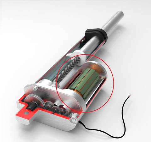
An actuator motor is the power generation component within a motion control system, responsible for converting electrical energy into mechanical rotation that drives subsequent mechanical systems. Unlike a standalone motor that simply spins a shaft, an actuator motor is specifically designed and selected to work within a complete actuation assembly where its rotational output is transformed into useful work—whether linear motion, rotary positioning, or controlled force application.
The term "actuator motor" encompasses several key concepts that are important to understand. First, the motor itself is typically a DC brushed motor, brushless DC motor, or stepper motor, chosen based on the specific performance requirements of the application. In the context of electric linear actuators, the motor provides the input rotary motion that is then converted through a gear train and lead screw mechanism into linear displacement.
What distinguishes an actuator motor from a general-purpose motor is its integration into a complete system designed for controlled, precise movement rather than continuous rotation. The motor works in concert with several other critical components: a gearbox that reduces speed and multiplies torque, a conversion mechanism (such as a lead screw for linear motion or a gear segment for rotary motion), limit switches or sensors that define travel boundaries, and often feedback devices that report position or force data back to a controller.
The motor's role is to provide sufficient rotational force and speed to overcome the load requirements of the application while operating within acceptable current, voltage, and thermal parameters. In a micro linear actuator, for instance, a small DC motor might operate at 12V and draw less than 2 amps while producing enough torque through the gear reduction to push or pull loads of 50-200 pounds. In contrast, an industrial actuator might use a larger motor operating at 24V or higher voltages, capable of moving loads exceeding 2,000 pounds.
Understanding that the actuator motor is part of an integrated system is crucial for troubleshooting, maintenance, and replacement. When an actuator fails, the motor itself may be functioning perfectly—the issue could lie in the gearbox, lead screw, limit switches, or other components. Conversely, motor failure (often due to brush wear, winding failure, or bearing deterioration) may require replacement while the rest of the actuation system remains serviceable.
Types of Actuator Motors and Their Applications
Actuator motors come in several distinct configurations, each optimized for specific performance characteristics, duty cycles, and application requirements. The primary categories—brushed DC, brushless DC, and stepper motors—represent different approaches to converting electrical energy into mechanical rotation, with significant implications for control precision, efficiency, maintenance requirements, and cost.
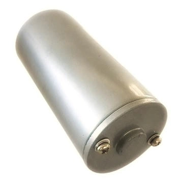
Brushed DC Motors
Brushed DC motors remain the most common choice for linear actuators due to their simplicity, cost-effectiveness, and ease of control. These motors use physical brushes and a commutator to switch current direction in the motor windings as the shaft rotates, creating continuous rotation. In typical linear actuator applications, brushed DC motors operate at 12V or 24V, with current draw varying from less than 1 amp for micro actuators to 6-8 amps or more for high-force units.
The advantages of brushed motors include straightforward speed control through voltage variation, simple reversibility by switching polarity, and relatively low initial cost. However, the physical brushes wear over time, typically representing the motor's primary failure mode. Brush life depends heavily on duty cycle, load, and operating environment—a motor in continuous industrial use may require replacement after 1,000-2,000 hours of operation, while an actuator used intermittently in a home automation application might last 10-15 years.
Brushless DC Motors
Brushless DC (BLDC) motors eliminate the physical brush-commutator interface by using electronic commutation controlled by Hall effect sensors or back-EMF sensing. This design dramatically extends motor life—often to 10,000+ hours of continuous operation—and improves efficiency by 10-30% compared to brushed motors. These advantages make BLDC motors ideal for high-duty-cycle applications, precision positioning systems, and environments where maintenance access is difficult.
The tradeoff for these benefits is increased complexity and cost. BLDC motors require dedicated controller electronics to manage the commutation sequence, which adds to both the initial system cost and the complexity of replacement. In applications where the actuator operates infrequently or where initial cost is paramount, the advantages of brushless motors may not justify their higher price point.
Stepper Motors
Stepper motors represent a fundamentally different approach to motion control, moving in discrete steps (typically 200 steps per revolution) rather than smooth continuous rotation. Each electrical pulse sent to the motor advances the shaft by one step, providing inherent position control without requiring feedback sensors. This open-loop positioning capability makes stepper motors attractive for applications requiring precise, repeatable positioning without the cost and complexity of encoder feedback systems.
In actuator applications, steppers excel where the load is predictable and consistent, allowing the controller to track position simply by counting steps. However, stepper motors can lose steps if the load exceeds their torque capacity or if acceleration rates are too aggressive, leading to position errors. For critical applications, feedback actuators that incorporate encoders or potentiometers provide verification of actual position regardless of motor type.
How Electric Linear Actuators Work: From Rotation to Linear Motion
The transformation from electrical energy to controlled linear motion involves a carefully engineered mechanical system that works in concert with the actuator motor. Understanding this conversion process is essential for proper actuator selection, troubleshooting, and optimization for specific applications.
The Gear Reduction System
The first stage after the motor is typically a multi-stage gear reduction system. Electric motors operate most efficiently at relatively high speeds—often 3,000-10,000 RPM for small DC motors. However, useful actuation work usually requires much lower speeds and much higher torque than the motor produces directly. The gearbox solves this fundamental mismatch.
A typical linear actuator might employ a 50:1 or 100:1 gear reduction, meaning the motor shaft rotates 50 or 100 times for each single rotation of the output gear. This reduction proportionally increases torque while decreasing speed. A motor producing 5 oz-in of torque at 5,000 RPM might, through a 60:1 reduction, produce 300 oz-in (nearly 19 lb-in) of torque at about 83 RPM at the output gear.
The gear reduction ratio directly impacts the actuator's performance characteristics. Higher ratios produce greater force and better holding power but slower extension and retraction speeds. Lower ratios yield faster movement but reduced force capacity. This fundamental tradeoff means that actuator selection must carefully balance speed and force requirements for the specific application.
The Lead Screw Mechanism
The heart of a linear actuator is the lead screw assembly that converts the gearbox's rotary output into linear motion. A lead screw is a threaded rod with a precisely machined helical thread. A lead nut (also called a drive nut) with matching internal threads rides on this screw. As the screw rotates, the nut is forced to move linearly along the screw's length—or conversely, if the nut is prevented from rotating, it translates along the stationary screw.
The lead screw's pitch—the axial distance traveled in one complete revolution—is a critical specification. Common pitches range from 2mm to 10mm in metric units, or 0.100" to 0.500" per revolution in imperial measurements. A 5mm pitch screw rotating at 60 RPM will extend or retract at 300mm per minute (about 12 inches per minute or 0.2 inches per second).
Lead screws come in two primary configurations: standard trapezoidal threads (also called ACME threads in the US) and ball screws. Trapezoidal threads are simpler and less expensive, with the nut sliding directly on the screw threads. This design creates significant friction, which actually provides beneficial load-holding capability—the actuator won't back-drive under load when power is removed. However, this friction limits efficiency to about 25-40%.
Ball screws use recirculating ball bearings between the screw and nut, dramatically reducing friction and increasing efficiency to 85-95%. This higher efficiency allows for faster speeds, longer life, and reduced motor current at a given load. However, ball screws require separate braking mechanisms to hold position when unpowered, as their low friction allows back-driving under load.
Housing and Extension Tube Assembly
The complete linear actuator assembly consists of a main body housing (containing the motor, gearbox, and lead screw) and a telescoping extension tube (connected to the lead nut). As the motor rotates the lead screw, the nut translates linearly, carrying the extension tube with it. This creates the familiar pushing or pulling motion of the actuator.
The stroke length—the total distance the actuator can extend and retract—is determined by the length of the lead screw and the travel limits imposed by internal limit switches or mechanical stops. Standard stroke lengths range from as little as 1-2 inches for micro actuators to 48 inches or more for long-stroke industrial units. Track actuators can achieve even longer strokes by using external guide rails to support extended lengths.
Benefits of Using Electric Linear Actuators
Electric linear actuators have increasingly replaced hydraulic and pneumatic systems across industrial, commercial, and consumer applications. This shift is driven by several compelling advantages that make electric actuation the preferred choice for most modern motion control challenges.
Precision and Repeatability
Electric actuators deliver positioning accuracy that hydraulic and pneumatic systems struggle to match. A quality electric linear actuator can achieve positional repeatability within ±0.1mm across thousands of cycles. When paired with feedback actuators that incorporate potentiometers, encoders, or Hall effect sensors, closed-loop control systems can achieve even finer resolution, tracking position to within microns for precision applications.
This precision stems from the mechanical nature of the lead screw conversion—each motor rotation corresponds to a predictable, consistent linear displacement. Unlike fluid-based systems where compressibility, temperature variations, and seal friction create positioning uncertainties, electric systems provide deterministic motion that can be accurately controlled and predicted.
Simplified Installation and Maintenance
Electric actuators require only electrical power connections—typically simple two-wire hookups to a power supply. There are no hydraulic hoses to route, no pneumatic compressors to install, no fluid reservoirs to fill, and no pressure regulators to adjust. This simplicity dramatically reduces installation time and complexity, particularly for distributed automation systems requiring multiple actuators.
Maintenance requirements are similarly minimal. A well-designed electric actuator operating within its duty cycle and load ratings may require no maintenance for years. There are no fluids to monitor or replace, no filters to change, no seals to inspect for leaks, and no air lines to check for leaks. When service is eventually required, it typically involves motor replacement or lead screw lubrication—straightforward procedures that don't require hydraulic system expertise.
Energy Efficiency
Electric linear actuators consume power only during active movement. When stationary—even under load—a properly designed actuator with sufficient mechanical advantage draws zero continuous power. The self-locking nature of trapezoidal lead screws means the actuator holds position mechanically, requiring no energy input. This stands in stark contrast to hydraulic systems that often run continuously, or pneumatic systems that constantly consume compressed air to maintain cylinder position.
For intermittent-duty applications—which represent the majority of actuator use cases—this efficiency advantage translates to dramatic energy savings. A standing desk that adjusts height twice daily uses negligible energy compared to a pneumatic desk system that would require continuous compressor operation.
Clean and Environmentally Friendly Operation
Electric actuators eliminate the environmental and cleanliness concerns inherent in fluid power systems. There are no hydraulic oil leaks to contaminate products or workspaces, no pneumatic exhaust ports releasing moisture and oil mist, and no disposal requirements for spent hydraulic fluid. This clean operation makes electric actuators ideal for food processing, pharmaceutical manufacturing, medical devices, and other applications where contamination is unacceptable.
Flexible Control Integration
Modern electric actuators integrate seamlessly with digital control systems, PLCs, microcontrollers like Arduino, and IoT platforms. Simple on-off control can be implemented with basic switches and relays, while sophisticated motion profiles requiring coordinated multi-axis movement, speed ramping, and force limiting can be achieved with dedicated control boxes or programmable controllers. This flexibility allows the same basic actuator hardware to serve applications ranging from simple manual control to fully automated, network-connected systems.
Rotary Actuators: Converting Motor Rotation to Controlled Angular Motion
While linear actuators convert motor rotation into straight-line motion, rotary actuators transform that same rotary input into controlled angular positioning or oscillation. Despite the different output motion, many of the same motor types and control principles apply, with the key differences lying in the mechanical conversion system.
Rotary Actuator Mechanisms
Electric rotary actuators use several different mechanical approaches to achieve controlled angular motion. The simplest design employs direct motor coupling with gear reduction, where the motor drives through a gearbox to a rotating output shaft. This configuration provides continuous 360-degree rotation with high torque and precise speed control, making it suitable for applications like valve operators, conveyor indexing, and rotating platforms.
For applications requiring limited angular travel—typically 90, 180, or 270 degrees—rack-and-pinion or scotch yoke mechanisms convert linear actuator motion into rotary output. These designs effectively use a linear actuator to drive a lever arm, creating rotational movement. The mechanical advantage of the lever arm length determines the torque output and angular speed relationship.
Applications and Advantages
Rotary actuators excel in applications where pivoting or rotating motion is required within a compact footprint. Common uses include automated valve operation in process control systems, where quarter-turn actuators open and close ball valves or butterfly valves with precise torque control. In robotics, small rotary actuators provide joint articulation, while in material handling, larger units index conveyor belts or rotate pallets for multi-sided access.
The primary advantage of electric rotary actuators over pneumatic or hydraulic rotary actuators is the same precision and control that benefits linear designs. Position can be held accurately, speed can be controlled precisely, and the system responds immediately to control signals without the delay inherent in fluid systems. Additionally, the compact design allows high torque output in small packages—a 3-inch diameter rotary actuator can easily produce 200-500 lb-in of torque.
Selecting the Right Actuator Motor for Your Application
Proper actuator selection requires careful analysis of several key parameters that define your application's requirements. Choosing an undersized actuator leads to premature failure and unreliable operation, while oversizing increases cost unnecessarily and may create integration challenges.
Load Capacity and Force Requirements
The first and most critical specification is the force or torque the actuator must produce. For linear actuators, this is typically specified in pounds (lb) or Newtons (N) of push or pull force. Calculate the maximum load the actuator must move, including the weight of the object, any friction forces that must be overcome, and safety factors for unexpected loads or binding conditions.
Most applications require different force in push and pull directions due to the load's orientation relative to gravity. Always specify force requirements for both directions. Manufacturers typically rate actuators with a static holding force (how much load can be supported when stationary) and a dynamic force (available force while moving). The dynamic force is always lower due to friction and efficiency losses in the moving system.
For vertical lifting applications, calculate the total weight being lifted and add at least a 25-50% safety factor. If lifting a 100-pound load vertically, specify an actuator rated for at least 125-150 pounds. For horizontal pushing applications, consider friction coefficients and any incline angles that add gravitational load components.
Speed and Stroke Requirements
Determine how far the actuator must extend (stroke length) and how quickly it must complete that movement. Standard actuators typically operate at speeds from 0.5 inches/second to 2 inches/second, though specialized high-speed units can reach 6-8 inches/second or more. Remember that speed and force are inversely related through the gear reduction ratio—faster actuators generally produce less force at a given motor power level.
Stroke length impacts several factors beyond obvious dimensional requirements. Longer strokes require longer lead screws, which can experience greater deflection under load and may need intermediate support. Additionally, actuator life is directly impacted by stroke—a unit with a 10-inch stroke rotates its motor 5 times as many revolutions as a 2-inch stroke unit to complete the same number of extension cycles, potentially reducing motor life proportionally.
Duty Cycle Considerations
Duty cycle—the percentage of time the actuator operates versus rests—critically impacts motor selection and actuator life. Motors generate heat during operation, and this heat must dissipate during rest periods. Continuous-duty applications (duty cycles approaching 100%) require motors with better thermal management, often necessitating brushless motors or industrial-grade brushed motors with enhanced cooling.
Most consumer and light commercial actuators are rated for 20% duty cycle or less, meaning they should operate no more than 2 minutes out of every 10. Exceeding this rating leads to motor overheating, potential thermal damage, and dramatically shortened life. For high-duty applications, specify industrial actuators explicitly rated for continuous or high-duty operation.
Environmental Considerations
Operating environment significantly impacts actuator selection. Standard actuators with IP42-IP54 ratings provide basic protection against dust and light moisture, suitable for indoor applications. Outdoor installations, wash-down environments, or applications exposed to moisture require actuators with IP65 or IP66 ratings, featuring sealed housings and corrosion-resistant materials.
Temperature extremes also matter. Standard actuators typically operate across -10°C to +50°C (14°F to 122°F). Applications outside this range require specialized actuators with temperature-appropriate lubricants, seals, and motor specifications. High-vibration environments may require mounting brackets with vibration isolation, while applications with shock loads need actuators with reinforced internal components.
How to Replace an Actuator Motor: A Step-by-Step Guide
Motor replacement represents one of the most common actuator service procedures. While the motor itself is designed to be replaceable, the procedure requires careful attention to mechanical alignment, electrical connections, and testing to ensure reliable operation after service.
Preparation and Safety
Before beginning any actuator service work, completely disconnect all power sources. For actuators connected to power supplies or control boxes, remove input power and disconnect actuator wiring. If the actuator is under load or in a position where it could move unexpectedly, mechanically lock or support the load before proceeding.
Gather necessary tools: appropriate screwdrivers (typically Phillips or hex/Allen keys), soldering equipment if electrical connections aren't plug-type, heat-shrink tubing or electrical tape for insulation, and general hand tools. Have the replacement motor on hand and verify it matches the original motor specifications—voltage, current rating, shaft diameter, and mounting pattern must all match.
Accessing the Motor
The actuator motor is typically housed in the fixed end of the actuator body—the end opposite the extending rod. Most designs use a removable end cap held by several screws (commonly 2-4 screws). Remove these mounting screws, taking care not to lose any washers or spacers, and carefully separate the end cap from the main body.
With the end cap removed, you'll typically see the motor secured to a mounting plate or motor bracket with two long screws that pass through the motor body into the gearbox housing. Note the motor's rotational orientation and the routing of the motor wires before proceeding with removal—you'll need to replicate this exact configuration during reassembly.
Removing the Old Motor
Disconnect the motor's electrical connections. In higher-quality actuators, these may be plug-type connectors that simply pull apart. More commonly, motor wires are soldered directly to circuit board terminals or to wires leading to the actuator's external connection point. If soldered, carefully desolder these connections, noting which wire connects to which terminal (though for DC motors, polarity can be reversed to change direction).
Remove the motor mounting screws. These typically pass from outside the actuator body, through the motor, and thread into the gearbox or main housing. As you remove the final screw, support the motor to prevent it from dropping. Carefully withdraw the motor, ensuring the motor shaft disengages cleanly from the gearbox input. If the shaft resists removal, check for retaining clips, set screws, or interference fits that must be released.
Installing the New Motor
Position the new motor, carefully aligning the motor shaft with the gearbox input coupler or gear. The shaft must engage fully without binding or misalignment. Rotate the motor shaft slightly while pressing the motor into position if needed to help the shaft teeth mesh with the gearbox gear teeth.
Once the motor is fully seated against its mounting surface, install the motor mounting screws. Tighten these screws evenly in a cross-pattern to ensure uniform clamping force and proper motor alignment. Don't overtighten—you're securing into relatively soft aluminum or plastic housings that can strip if excessive force is applied.
Reconnect the electrical connections. If using plug connectors, ensure they're fully seated and locked. If soldering, create clean, mechanically strong joints with good electrical contact. Use heat-shrink tubing or electrical tape to insulate any exposed connections and prevent shorts against the metal housing. Route wires to prevent pinching when the end cap is reinstalled.
Testing and Verification
Before fully reassembling the actuator, connect power and perform initial testing. Start with very brief power applications to verify correct motor rotation. If the motor runs but the actuator extends when it should retract (or vice verса), reverse the motor polarity by swapping the motor wire connections.
Once correct direction is verified, allow the actuator to complete full extension and retraction cycles. Listen for unusual noises that might indicate misalignment or binding. Check that limit switches properly stop motor operation at both travel extremes. Verify that the motor doesn't overheat during normal operation cycles—some warmth is normal, but excessive heat indicates problems.
After successful testing, reassemble the end cap, ensuring any gaskets or seals are properly positioned to maintain the actuator's environmental rating. Perform final operational tests under actual load conditions before returning the actuator to service.
Maximizing Actuator Motor Life Through Proper Maintenance
While electric linear actuators are relatively low-maintenance devices, proper care extends motor life and ensures reliable operation. Understanding the factors that affect longevity allows you to maximize return on investment and minimize unexpected downtime.
Factors Affecting Motor Life
Several interconnected factors determine how long an actuator motor will operate reliably. For brushed DC motors—the most common type in linear actuators—brush wear represents the primary failure mode. Brushes are consumable components designed to wear over time, with typical lifespans ranging from 500 to 3,000 hours of actual operation depending on motor quality, current levels, and duty cycle.
Operating conditions dramatically impact motor life. Running at or near the actuator's maximum force rating generates higher motor current, accelerating brush wear and increasing thermal stress on motor windings. An actuator operated at 50% of its rated force will typically last 3-4 times longer than one consistently operated at maximum capacity.
Stroke length has a direct mathematical relationship with motor life. Consider two identical motors, one in a 2-inch stroke actuator and another in a 12-inch stroke actuator. If both complete 10,000 extension cycles, the longer-stroke motor has rotated six times as many revolutions, experiencing six times the brush wear and bearing stress. This explains why manufacturers often specify actuator life in terms of full extension cycles rather than motor hours—the stroke length is factored into the rating.
Preventive Maintenance Practices
Regular lubrication of the lead screw maintains efficiency and reduces motor load. Most manufacturers recommend applying a light machine oil or lithium-based grease to the exposed portion of the lead screw every 6-12 months or after 5,000 cycles, whichever comes first. Avoid over-lubrication, which attracts dust and debris that can accelerate wear.
Inspect mounting brackets and attachment points periodically for looseness or wear. A loose mounting forces the actuator to work harder to move the load, increasing motor current and reducing life. Proper mounting also ensures even load distribution along the actuator shaft, preventing side loading that stresses internal components.
For applications where actuators are idle for extended periods, operate them through several full cycles every few months. This prevents lubricant from settling, redistributes protective coatings, and identifies any developing issues before the actuator is needed for critical service.
Operating Within Specifications
Perhaps the most important factor in actuator longevity is operating within the manufacturer's specified parameters. Exceeding the rated force, even occasionally, dramatically accelerates wear on all components. Similarly, exceeding duty cycle ratings by not allowing adequate cooling time between operations causes cumulative thermal damage that shortens motor life.
Voltage matters too. Operating a 12V actuator on 24V doubles the motor's speed and force output but can reduce lifespan by 75% or more due to excessive current, heat generation, and mechanical stress. Conversely, under-voltage operation (running a 24V actuator on 12V) reduces force and speed but doesn't typically damage the motor—it simply may not provide adequate performance for the application.
Conclusion
Actuator motors represent the critical energy conversion component in modern electric motion control systems, transforming electrical power into precisely controlled mechanical movement. Whether integrated into linear actuators for push-pull applications or rotary actuators for angular positioning, these motors work within carefully engineered mechanical systems to deliver force, speed, and positioning accuracy that have largely replaced hydraulic and pneumatic alternatives across most applications.
Success with actuator motors depends on understanding the complete system—not just the motor itself, but the gearbox, lead screw or rotary mechanism, control system, and mounting arrangement. Proper selection requires careful analysis of force, speed, stroke, duty cycle, and environmental requirements. Installation must account for proper mounting, adequate power supply sizing, and appropriate control integration. And maintenance


