Creating a Force Shutoff Safety System for Linear Actuators
Safety is paramount in any automated system involving mechanical movement. When designing applications with linear actuators—whether it's a motorized trap door, automated window, adjustable furniture, or industrial equipment—the risk of injury or equipment damage from excessive force must be addressed. A critical safety feature in these systems is force-based overload protection that automatically cuts power when resistance exceeds safe thresholds.
Unlike simple limit switches that only detect position, a force shutoff safety system monitors the current draw of the actuator motor in real-time. Since motor current correlates directly with mechanical load, this approach provides dynamic protection against pinch points, obstructions, and mechanical binding. This is especially important in applications where people or objects might inadvertently enter the actuator's path of travel—scenarios where position-based protection alone would be insufficient.
In this comprehensive guide, we'll walk through implementing a professional-grade overcurrent protection system for linear actuators, including wiring configurations, programming procedures, and practical application examples. Whether you're a DIY enthusiast building a custom automation project or an engineer designing safety-critical equipment, understanding force-based protection is essential for responsible actuator implementation.
Understanding Overcurrent Protection in Linear Actuators
The principle behind force shutoff systems is elegantly simple: as mechanical resistance increases, the electric motor inside the actuator draws more current to maintain motion. By monitoring this current and establishing a threshold, we can detect when the actuator encounters unexpected resistance—whether from an obstruction, binding, or reaching the end of travel.
In a typical DC motor system, current draw varies significantly between no-load and full-load conditions. A linear actuator moving freely might draw 1-2 amperes, while the same actuator under maximum rated load could draw 4-6 amperes or more. When an actuator encounters an immovable object or mechanical failure, current can spike dramatically as the motor stalls.
Overcurrent protection controllers work by continuously measuring the current flowing to the actuator and comparing it against a user-defined setpoint. When the measured current exceeds this threshold for a predetermined duration (typically milliseconds to prevent false triggers from startup inrush), the controller interrupts power to the actuator. After a brief reset period, the system can resume normal operation once the obstruction is cleared.
Advantages Over Mechanical Limit Switches
While traditional limit switches serve an important role in position detection, force-based protection offers several distinct advantages:
- Dynamic protection anywhere in the stroke: Force monitoring works throughout the entire range of motion, not just at predetermined positions
- Obstacle detection: The system responds to unexpected objects or resistance, regardless of actuator position
- Adjustable sensitivity: Current thresholds can be tuned to match specific applications and safety requirements
- Bi-directional protection: Overcurrent monitoring works in both extension and retraction directions
- No mechanical wear: Electronic sensing eliminates the mechanical contact and wear associated with limit switches
The FIRGELLI FA-POCT Overcurrent Protection Controller
The FA-POCT (Programmable Over Current cut-off module) is a dedicated protection device engineered specifically for DC motor applications including linear actuators. This compact control box integrates seamlessly into existing wiring configurations and provides programmable current limiting from 1 to 5 amperes in 0.5-ampere increments.
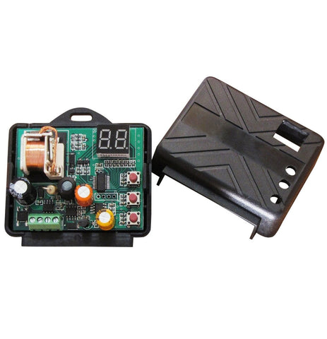
The controller features a three-button interface with an LED display for straightforward programming and status monitoring. Unlike basic circuit breakers that require manual reset, the FA-POCT automatically resets after a brief cooling period once the overcurrent condition is resolved. This makes it ideal for automated systems that need to recover from temporary obstructions without human intervention.
Key Technical Specifications
- Operating voltage: 12V DC or 24V DC compatible
- Adjustable current threshold: 1A to 5A in 0.5A steps
- Automatic reset function with timeout period
- LED display for programming and status indication
- Compact form factor for easy integration
- Compatible with single or dual actuator configurations
Wiring Configuration and Installation
Proper wiring is critical for both safety system functionality and reliable operation. The FA-POCT controller must be positioned in series between your power source and the linear actuator, allowing it to monitor current flow in real-time.
Basic Single Actuator Setup
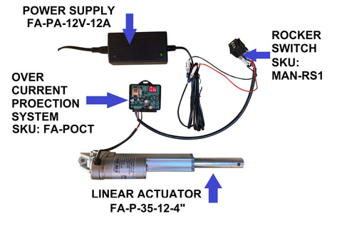
For a standard configuration with one actuator, the wiring sequence follows this path:
- Power supply (12V DC): Connect to a wall outlet and ensure adequate amperage rating for your actuator (typically 5-10 amps for most applications)
- Reversing switch: Install a DPDT (double-pole, double-throw) rocker switch or relay to control direction. The MAN-RS2 rocker switch provides a simple manual control interface
- FA-POCT controller: Wire the output from your switch to the controller input terminals
- Linear actuator: Connect the controller output to the actuator power leads
This configuration allows the reversing switch to control actuator direction while the FA-POCT monitors current in both directions. When an overcurrent event occurs, the controller interrupts the circuit regardless of which direction the actuator is traveling.
Dual Actuator Considerations
The FA-POCT can protect multiple linear actuators wired in parallel, but important considerations apply. When running actuators in parallel, the current draw combines—two identical actuators under identical loads will draw twice the current of a single unit. Therefore, if each actuator normally draws 2 amperes, the controller must be set to at least 4 amperes to accommodate both units.
For synchronized dual-actuator systems, ensure both actuators have matching specifications (stroke length, speed, and force ratings) to prevent uneven loading. Mismatched actuators can cause one unit to work harder than the other, leading to premature overcurrent trips or uneven motion.
Programming the Current Threshold
Setting the appropriate current threshold is crucial—too low and the system will nuisance-trip during normal operation; too high and protection may not activate when needed. The FA-POCT's programmable interface makes threshold adjustment straightforward.
Step-by-Step Programming Procedure
- Remove the controller cover: Unscrew or unclip the protective cover to access the control panel and buttons
- Observe the current display: The LED display shows the currently programmed threshold value in amperes
- Adjust the setpoint: Use the top button to increase the current value and the middle button to decrease. Values adjust in 0.5-ampere increments from 1.0A to 5.0A
- Save the setting: Press and hold the bottom button for approximately 2 seconds until the display confirms the setting has been saved
- Test the configuration: Apply external force to the actuator to verify the threshold triggers appropriately
Determining Optimal Threshold Values
The ideal current threshold depends on your specific application and actuator specifications. Here's a systematic approach to determining the right setting:
Measure baseline current: Using a multimeter in series with your actuator, measure the current draw under several conditions—no load (free movement), typical working load, and maximum rated load. This establishes your operational current range.
Calculate safety margin: Set your threshold above the maximum normal operating current but below the stall current. A typical approach is to set the threshold at 120-150% of maximum normal load current. For example, if your actuator draws 2.5A at maximum rated load, setting the threshold at 3.0-3.5A provides adequate protection while preventing false triggers.
Consider startup inrush: DC motors briefly draw higher current during startup. The FA-POCT includes internal timing to ignore these transient spikes, but extremely low threshold settings may cause issues if startup current approaches your setpoint.
Practical Application Examples
Force shutoff safety systems prove invaluable across numerous applications where human safety or equipment protection is paramount. Here are several real-world scenarios where overcurrent protection is essential:
Motorized Trap Doors and Hatches
Automated access doors in floors, ceilings, or walls present obvious pinch point hazards. A linear actuator with force monitoring can detect if someone's hand, foot, or an object is caught in the door's path and immediately stop movement. This is particularly important in theatrical applications, residential installations, or commercial buildings where untrained users might interact with the system.
Adjustable Furniture and Ergonomic Equipment
Height-adjustable desks, medical beds, and wheelchair lifts all benefit from force-based protection. If a standing desk encounters an object during height adjustment, the system should stop rather than continue applying force. Similarly, TV lifts hidden in cabinets or footboards can detect obstructions that might damage the television or surrounding cabinetry.
Automated Windows and Ventilation Systems
Motorized windows and skylights are subject to building codes requiring obstruction detection. Force-based protection ensures the window stops if something blocks its path—particularly critical for roof windows and skylights where manual intervention might be difficult. The same principle applies to automated greenhouse vents and industrial ventilation systems.
Industrial Machinery and Robotics
Manufacturing equipment using industrial actuators requires multiple layers of safety. Overcurrent protection serves as a backup to primary safety systems, detecting mechanical binding, part misalignment, or unexpected obstacles. This prevents damage to expensive tooling and workpieces while protecting operators from moving machinery.
System Operation and Reset Behavior
Understanding how the FA-POCT responds to overcurrent events is essential for proper system design and troubleshooting. When the controller detects current exceeding the programmed threshold, it immediately interrupts power to the actuator. This happens in both extension and retraction directions, providing comprehensive bi-directional protection.
After triggering, the controller enters a reset timeout period lasting several seconds. During this time, the system will not respond to control inputs, even if the obstruction is removed. This built-in delay serves two purposes: it allows the motor to cool slightly, and it prevents rapid cycling if the control system repeatedly attempts to drive the actuator into the obstruction.
Once the timeout period expires, the controller automatically resets to normal operation. No manual intervention is required—simply ensure the obstruction has been cleared and the actuator can move freely. If the overcurrent condition persists (for example, if the actuator has reached end-of-stroke without a limit switch), the controller will trip again immediately upon attempting movement.
Troubleshooting Nuisance Trips
If your system trips too frequently during normal operation, consider these factors:
Threshold too low: The most common cause of nuisance trips is an overcurrent setpoint below normal operating current. Measure actual current draw under load and increase the threshold appropriately.
Mechanical binding: Excessive friction in the actuator mechanism or mounting can cause abnormally high current draw. Check mounting brackets for misalignment and ensure the actuator rod moves freely through its entire stroke.
Voltage drop: Insufficient wire gauge or poor connections can cause voltage drop under load, forcing the motor to draw more current to maintain performance. Use appropriately sized wire (typically 18 AWG minimum for most 12V actuator applications).
Multiple actuators: Remember that parallel actuators combine their current draw. If running dual actuators, ensure your threshold accounts for both units.
Advanced Integration and Automation
While the basic setup uses manual switches, the FA-POCT integrates readily with more sophisticated control systems for automated operation.
Relay Control and Remote Operation
Replace manual switches with relays controlled by wireless receivers, timers, or sensors. A remote control system allows convenient operation from a distance while maintaining full overcurrent protection. The FA-POCT works transparently with any switching method since it monitors current rather than control signals.
Microcontroller Integration
For Arduino or other microcontroller projects, the FA-POCT provides hardware-level protection that complements software control. While your code manages normal actuator operation, the overcurrent controller serves as a fail-safe that operates independently of software reliability. This defense-in-depth approach is particularly important in safety-critical applications.
Feedback System Coordination
When using feedback actuators with position sensing, combine position-based control with force-based protection. The feedback signal allows precise positioning, while the FA-POCT provides force monitoring that position sensors cannot detect. This combination offers comprehensive control and protection—the feedback system handles normal operation and positioning, while force monitoring catches unexpected obstacles or binding.
Selecting Compatible Actuators and Components
The FA-POCT works with most DC linear actuators operating at 12V or 24V, but selecting appropriately rated components ensures optimal system performance.
Actuator Current Ratings
Different actuator types have varying current draws based on their force capacity and internal gearing. Micro linear actuators designed for light-duty applications might draw only 1-2 amperes at full load, while heavy-duty industrial actuators can draw 5-8 amperes or more. Ensure your FA-POCT threshold range (1-5A) accommodates your actuator's specifications, or consider multiple controllers for very high-force applications.
Power Supply Sizing
Your power supply must provide adequate amperage for your actuator plus a safety margin. A good rule of thumb is to size the supply for 150% of maximum expected current draw. For a single actuator drawing 3 amperes at peak load, a 5-ampere supply provides appropriate capacity. For dual actuators, double this accordingly.
Wire Gauge Considerations
Proper wire sizing prevents voltage drop and excessive resistance that can affect overcurrent threshold accuracy. For 12V systems drawing up to 5 amperes over distances up to 10 feet, use minimum 18 AWG wire. For longer runs or higher currents, consult wire ampacity tables and factor in voltage drop calculations to ensure less than 3% voltage drop at maximum current.
Maintenance and Long-Term Reliability
Once properly installed and programmed, the FA-POCT requires minimal maintenance. However, periodic checks ensure continued reliable operation:
Test protection function quarterly: Deliberately trigger the overcurrent protection by manually resisting actuator movement. Verify the controller cuts power appropriately and resets after the timeout period.
Inspect electrical connections: Check all wire terminations for corrosion, looseness, or damage. Poor connections can cause voltage drop or intermittent operation.
Monitor actuator performance: Changes in normal operating current may indicate developing mechanical problems. If you notice the actuator drawing more current than usual even without triggering protection, investigate for increased friction, wear, or binding.
Document threshold settings: Record your programmed current thresholds and the reasoning behind those values. This information proves invaluable if system troubleshooting or modification becomes necessary.
Conclusion
Implementing force-based safety protection in linear actuator systems represents responsible engineering practice that prioritizes safety without compromising functionality. The FIRGELLI FA-POCT overcurrent protection controller provides an accessible, reliable solution for applications ranging from DIY home automation to professional equipment manufacturing.
By monitoring current draw as a proxy for mechanical force, these systems detect obstacles and excessive loads that position-based sensing alone cannot catch. The straightforward installation, programmable thresholds, and automatic reset functionality make force shutoff protection practical for virtually any linear actuator application where safety matters.
Whether you're building a motorized trap door, automating industrial equipment, or creating adjustable furniture, force-based overcurrent protection should be a fundamental component of your safety strategy. Combined with proper mechanical design, appropriate actuator selection, and thoughtful system integration, this technology helps ensure your automated systems operate safely and reliably for years to come.
Frequently Asked Questions
What current threshold should I set for my linear actuator?
The optimal current threshold depends on your specific actuator and application. Start by measuring your actuator's current draw under maximum normal load using a multimeter. Set the FA-POCT threshold approximately 20-50% above this value to provide a safety margin while preventing nuisance trips. For example, if your actuator draws 2 amperes at maximum rated load, setting the threshold at 2.5-3.0 amperes typically works well. Remember to account for the combined current of multiple actuators if running them in parallel.
Can I use the FA-POCT with multiple actuators simultaneously?
Yes, the FA-POCT can protect multiple actuators wired in parallel, but you must account for their combined current draw. If you're running two identical actuators that each draw 2 amperes, you'll need to set the threshold at or above 4 amperes to accommodate both units. Keep in mind the FA-POCT's maximum setting is 5 amperes, so applications requiring higher total current may need multiple protection modules or higher-capacity alternatives. Always ensure actuators used in parallel have matching specifications to prevent uneven loading.
How long does the FA-POCT take to reset after an overcurrent trip?
After detecting an overcurrent condition and cutting power, the FA-POCT enters a reset timeout period lasting several seconds (typically 3-5 seconds). During this time, the controller will not respond to control inputs even if the obstruction is removed. This delay serves as a safety feature, preventing rapid cycling and allowing the motor to cool. Once the timeout expires, the system automatically returns to normal operation—no manual reset is required. Simply ensure the obstruction has been cleared before attempting to operate the actuator again.
Does overcurrent protection work in both extension and retraction directions?
Yes, the FA-POCT monitors current and provides protection in both directions of actuator travel. Whether your actuator is extending or retracting, if it encounters resistance exceeding the programmed threshold, the controller will immediately cut power. This bi-directional protection is essential for comprehensive safety, as hazards can occur during any phase of actuator movement. The single current threshold applies to both directions, so there's no need to program separate setpoints.
What causes frequent nuisance trips and how can I prevent them?
Nuisance trips typically result from a threshold set too low for normal operating conditions. First, verify your current setpoint is above the actuator's peak operating current by at least 20%. Other common causes include mechanical binding from misaligned mounting brackets, excessive friction in the actuator mechanism, undersized wiring causing voltage drop, or forgetting to account for multiple actuators' combined current draw. Use a multimeter to measure actual current during normal operation, then adjust the threshold appropriately. If mechanical issues are suspected, inspect all mounting points and connections for proper alignment and ensure the actuator rod moves freely throughout its stroke.
Can I integrate the FA-POCT with Arduino or other microcontroller systems?
Absolutely. The FA-POCT works as a hardware-level protection device that operates independently of your control system, making it ideal for microcontroller projects. Your Arduino or other controller can manage normal actuator operation through relays or motor drivers, while the FA-POCT provides fail-safe overcurrent protection that functions regardless of software state. This defense-in-depth approach is particularly valuable in safety-critical applications, as the hardware protection continues working even if software crashes or malfunctions. Simply wire the FA-POCT in series between your motor driver output and the actuator—no special programming or communication is required.
What wire gauge should I use for my actuator and protection system?
For typical 12V systems with actuators drawing up to 5 amperes, use minimum 18 AWG wire for runs up to 10 feet. For longer distances or higher currents, upsize accordingly—16 AWG for 15-20 foot runs or currents up to 8 amperes. Undersized wire causes voltage drop that can affect actuator performance and make overcurrent threshold setting more difficult. Calculate voltage drop for your specific installation to ensure less than 3% drop at maximum current. Good quality stranded copper wire with proper insulation rating ensures reliable long-term operation and accurate current monitoring by the FA-POCT controller.


