Starting an automation project can feel overwhelming, especially when faced with technical specifications, electrical requirements, and control systems. Whether you're automating a camper van bed lift, building a hidden TV cabinet, or creating a custom pop-up window mechanism, success comes down to methodical planning and understanding your specific requirements. The good news? Most automation projects follow predictable patterns, and with the right approach, you can confidently select components and design a system that works reliably for years.
🎥 Video — Planning a New Automation Project
At FIRGELLI Automations, we've supported thousands of projects—from simple single-actuator installations to complex multi-axis systems. Through this experience, we've identified the key questions and considerations that separate successful projects from frustrating ones. This guide will walk you through the complete planning process, from initial concept to component selection, with practical examples for the most common application types. By the end, you'll have a clear roadmap for turning your automation idea into reality.
Defining Your Project Requirements
Before selecting any components, you need a clear understanding of what your system must accomplish. This requirements phase is where most problems are prevented—or inadvertently created. Taking the time to answer these fundamental questions will save you from costly mistakes and multiple component revisions.
Application Type and Scope
Start by defining whether you're retrofitting linear actuators into an existing mechanism or designing something entirely new. Retrofits often have fixed mounting points and spatial constraints that limit your options, while new designs offer more flexibility but require more upfront planning. Consider the environment as well—will this operate indoors in controlled conditions or outdoors where moisture, temperature extremes, and dust become factors?
Load and Force Calculations
Understanding the load requirements is perhaps the most critical specification. Actuator force ratings assume axial loads—meaning the force is applied directly along the actuator's centerline. For vertical lifting applications, this calculation is straightforward: if you're lifting 50 pounds, you need actuators with a combined rating exceeding 50 pounds, plus a safety margin of 20-30% to account for friction and binding.
Non-linear applications like hinges require more sophisticated calculations because the effective load changes throughout the motion arc. A 100-pound lid might only require 40 pounds of force when the actuator is positioned optimally, or it might require 150 pounds if poorly positioned. We'll explore these calculations in detail in the hinged applications section.
Stroke Length Requirements
Stroke length—the total distance the actuator rod extends and retracts—must match or exceed your required motion. However, selecting the exact stroke you need isn't always optimal. It's often better to choose a slightly longer stroke and use external limit switches to control the exact stopping points. This approach provides adjustment flexibility during installation and prevents the actuator from dead-driving (continuing to push after reaching its mechanical limit), which can damage both the actuator and your application.
Speed and Duty Cycle Considerations
Actuator speed and force exist in an inverse relationship—higher force typically means slower speed, and vice versa. Most linear actuators move between 0.5 to 2 inches per second depending on load and voltage. For most home and light commercial applications, speed is less critical than reliability and smooth operation.
Duty cycle refers to how long an actuator can operate continuously before requiring a rest period to cool down. At FIRGELLI, we rate duty cycles based on 5 minutes of continuous motion. For typical applications—opening a cabinet door, lifting a bed, extending a platform—duty cycle is rarely a concern because the motion time is measured in seconds, not minutes. Industrial applications requiring repeated cycles throughout the day need more careful duty cycle consideration.
Special Features and Control Requirements
Consider whether your application requires advanced features like collision detection, soft start/stop, position feedback, or variable speed control. Feedback actuators provide real-time position data, enabling precise control and synchronization. Some requirements can be met through clever control schemes and relay logic rather than specialized actuators, potentially reducing system cost and complexity.
Essential System Components
Every actuator system requires three fundamental component categories: the actuator assembly, the control system, and the power source. Understanding how these work together helps you design a reliable, maintainable system.
Actuator and Mounting Hardware
The actuator itself is just one part of the mechanical assembly. Mounting brackets are actuator-specific and critical for transferring force safely. Using improper brackets or mounting methods can result in side-loading (lateral forces perpendicular to the actuator rod), which causes premature wear, binding, and failure. Always verify bracket compatibility with your specific actuator model, and ensure mounting surfaces are solid and properly aligned.
Control Systems
The control system is responsible for reversing the polarity to the motor, which changes the direction of actuator motion. Options range from simple rocker switches to sophisticated control boxes with built-in relay logic, to programmable Arduino-based systems for complex multi-actuator synchronization.
For beginners, a basic control system consists of a DPDT (double-pole, double-throw) switch that reverses polarity. More advanced users might implement remote control systems, integrate with home automation platforms, or use PLCs for industrial applications. The control scheme is where most customization happens—it's how you implement safety features, synchronization, and integration with other systems.
Power Source Selection
Your power supply must exceed the cumulative amperage draw of all actuators running simultaneously. Most FIRGELLI actuators operate on 12V DC, though 24V options are available for higher-force applications. A common mistake is undersizing the power supply, which leads to voltage sag under load, causing erratic operation, slow speeds, and potential motor damage.
For the simplest possible system, consider a complete package like the CSPS Wired Power & Control System, which includes power supply, control switch, and wiring for a single actuator with up to 5A draw. This eliminates guesswork for first-time builders and ensures component compatibility.
Vertical Lifting Applications
Vertical lifting represents the most straightforward type of actuator application because everything moves in a straight line parallel to gravity. There are no angular calculations, no changing load vectors—just addition and subtraction. This makes vertical lifts ideal for first-time automation projects.

Common Vertical Lift Projects
Kitchen appliance lifts are among the most popular vertical applications. These systems raise heavy mixers, blenders, or other appliances from base cabinets to counter height, eliminating the need to lift heavy equipment manually. FIRGELLI offers dedicated TV lift kits that include the actuator, telescopic frame, and mounting hardware—essentially an all-in-one solution that simplifies installation.
Camper van bed lifts represent another widespread use case. These systems typically use 2-4 synchronized actuators to raise a sleeping platform toward the ceiling during the day, creating living space below. The key challenge here is synchronization—all actuators must move at exactly the same speed to prevent the bed from binding or tilting. This usually requires either matched feedback actuators with electronic synchronization or a mechanical linkage that forces parallel motion.
Design Principles for Vertical Motion
The actuator orientation doesn't affect function in vertical applications—you can mount with the rod pointing up or down. What matters is solid mounting and proper alignment. The actuator should move perfectly parallel to the intended motion path. Any misalignment creates side-loading, which increases friction and reduces actuator lifespan.
For applications where precise tracking is critical, incorporate slide rails or drawer slides to guide the motion. The actuator provides the force, while the rails handle any lateral loads and ensure smooth, binding-free travel. This is particularly important for heavier loads or applications where the moving object might not be perfectly balanced.
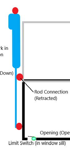
Practical Example: Pass-Through Window Lift
Let's design a vertical lift for a 20-inch tall pass-through window weighing 25 pounds including the frame. The window rides on vertical tracks for guidance. First, we determine force requirements: 25 pounds moving weight plus a 25% safety margin equals roughly 32 pounds minimum. Most standard actuators rated for 50+ pounds would be appropriate, but selecting a higher-rated unit (100-200 pounds) provides a safety margin and typically means smoother, quieter operation.
For stroke length, the window is 20 inches tall. Available strokes might be 18 inches and 24 inches. The 18-inch option would leave 2 inches of window visible when "closed," which likely isn't acceptable. The 24-inch stroke is the correct choice, even though it exceeds requirements. The extra stroke can be limited using external limit switches.
This application could use either a single actuator pulling from the center top of the window or two synchronized actuators mounted vertically on either side. The single-actuator approach is simpler but requires the window to be well-balanced and properly guided by the tracks. The dual-actuator approach distributes force more evenly and is more forgiving of slight imbalances.
Implementing External Limit Switches
For the window example, we don't want the actuator to dead-drive when the window reaches the fully closed position. An external limit switch positioned to trigger when the window contacts the sill will cut power to the actuator, preventing over-force situations. The fully open position can use the actuator's internal limit switch, or you can add a second external switch for precise positioning control.
Horizontal Sliding Applications
Horizontal sliding operations are nearly as straightforward as vertical lifts, with one crucial difference: the actuator isn't supporting the full weight of the moving object. Instead, it's overcoming friction in the sliding mechanism. This typically means much lower force requirements than you might initially expect.

Common Horizontal Applications
Slide-out drawers and stairs in RVs and campers represent the most common horizontal applications. Deployable solar panel arrays, extending platforms, and side-moving hidden TVs all follow similar principles. The key is creating a smooth, low-friction sliding mechanism before adding the actuator—trying to use actuator force to overcome a poorly designed slide mechanism is a recipe for failure.
Selecting Appropriate Slides
The sliding mechanism—whether drawer slides, slide rails, or linear bearings—bears the actual weight load in horizontal applications. Choose slides rated for at least 150% of your moving object's weight to ensure smooth operation and long service life. Heavy-duty ball bearing slides offer the smoothest action and lowest friction, while roller slides handle heavier loads but with slightly more resistance.

Calculating Horizontal Force Requirements
The actuator force needed for horizontal motion depends entirely on the friction in your sliding mechanism. High-quality ball bearing slides might have friction coefficients as low as 0.05, meaning a 100-pound object requires only 5 pounds of force to move. Basic roller slides might have coefficients of 0.15 or higher, requiring 15+ pounds of force for that same 100-pound load.
If you can't find friction specifications for your slides, a practical approach is to manually push the loaded assembly. If you can move it smoothly with one hand, a micro linear actuator rated for 25-50 pounds will easily automate it. If it requires noticeable effort to move, select a standard actuator rated for 100+ pounds. The most conservative approach is to select an actuator capable of vertically lifting your object's weight—this guarantees adequate force for horizontal motion regardless of friction.
Installation Best Practices
Install and test the sliding mechanism first, before adding the actuator. The object should glide smoothly through its full range of motion with minimal hand pressure. If there's binding, racking, or hard spots, fix these issues before proceeding. The actuator will not "power through" a poorly functioning slide mechanism—it will stall, draw excessive current, overheat, and eventually fail.
Position the actuator to push or pull as close to parallel with the direction of motion as possible. Angled mounting creates unnecessary side loads on both the actuator and the sliding mechanism. If space constraints force an angled installation, ensure your slides can handle the resulting lateral forces.
Hinged Applications
Hinged applications represent the most complex common use case for linear actuators because the geometry constantly changes throughout the motion cycle. As a lid, hatch, or door rotates around its hinge point, the actuator's angle of attack changes, which means the effective force varies from fully closed to fully open. This requires more careful planning than vertical or horizontal applications.

Understanding Hinge Geometry
When you mount an actuator to automate a hinged object, you're creating a triangle with constantly changing angles. The three points of this triangle are: the hinge pivot point, the mounting point on the moving object (lid/door), and the mounting point on the stationary object (base/frame). As the lid opens, this triangle changes shape—the hinge point stays fixed, but the distance between the two mounting points must equal the actuator's length at any given position.
This geometric relationship means you have three interdependent variables: actuator stroke length, mounting position on the lid (distance from hinge), and required actuator force. Change any one of these, and the others must adjust accordingly. There's rarely a single "correct" solution—instead, there's a range of workable configurations, each with different trade-offs.
Determining Stroke Length for Hinges
Start by establishing your mounting points based on physical constraints—where can you actually attach the actuator given your structure, clearances, and aesthetics? Measure the distance between mounting points when the lid is closed (this equals your retracted actuator length) and when the lid is fully open (this equals your extended actuator length). The difference between these measurements is your required stroke.

FIRGELLI's Linear Actuator Calculator simplifies this process by letting you input your hinge geometry and testing different actuator options virtually. This tool helps you visualize how different mounting positions affect both stroke requirements and force requirements, enabling informed decisions before you start drilling holes.
Force Requirements for Hinged Lids
The force needed to lift a hinged lid varies dramatically based on mounting geometry. A lid that's horizontal requires maximum force because gravity acts perpendicular to the surface—you're supporting the full weight. As the lid angles upward, the force requirement decreases. However, the actuator's angle relative to the lid also matters tremendously.
When the actuator pushes perpendicular to the lid surface, it has maximum mechanical advantage. When it pushes at a shallow angle nearly parallel to the lid, much of the force is "wasted" compressing the hinge rather than rotating the lid. This is why two different mounting positions can require vastly different actuator forces for the same lid weight.

Mounting Position Trade-offs
Mounting closer to the hinge joint requires higher force but shorter stroke. This configuration might be necessary when space is limited or when you want the actuator hidden near the hinge line. Mounting farther from the hinge requires lower force but longer stroke, and the actuator will be more visible but often more efficient.

Consider these factors when choosing mounting positions:
- Clearance: Will the actuator interfere with anything during operation? Remember it sweeps through an arc as it extends and retracts.
- Aesthetics: Can you hide the actuator, or is visibility acceptable for your application?
- Structural strength: Are the mounting surfaces strong enough to handle the forces without flexing or pulling out?
- Maintenance access: Can you reach the actuator for future maintenance or replacement?

Example: Mounting Position Comparisons
Let's examine two mounting options for the same application to understand the force implications. In both cases, we're automating a 100-pound horizontal lid that opens 90 degrees.
Mounting Position 1 (Near Hinge): Actuator mounts 8 inches from the hinge on the lid and 6 inches from the hinge on the base. This geometry creates a poor angle when the lid is horizontal, requiring perhaps 200+ pounds of force at the worst point in the motion. However, the required stroke might only be 10 inches, and the actuator stays relatively hidden.
Mounting Position 2 (Far from Hinge): Actuator mounts 20 inches from the hinge on the lid and 8 inches from the hinge on the base. This geometry provides better mechanical advantage, potentially requiring only 80-100 pounds of force. However, the stroke requirement increases to perhaps 20 inches, and the actuator is more visible.

Neither option is inherently better—the choice depends on your specific constraints, available actuator options, and priorities. This is why hinge applications benefit so much from using the calculator to model different scenarios before committing to a design.
Precision and Advanced Applications
Some applications require position accuracy measured in millimeters, synchronized multi-actuator motion, or integration with external control systems. These precision applications include Stewart platforms for motion simulation, scientific testing equipment, and coordinated multi-axis systems.

When Feedback is Essential
Feedback actuators incorporate position sensors that provide real-time data about rod extension. This enables closed-loop control where the system continuously adjusts to maintain precise positioning, compensate for varying loads, or synchronize multiple actuators with millimeter accuracy. For applications like adjustable height desks, feedback allows position memory—returning to saved heights with repeatable accuracy.
Arduino and Programmable Control
For complex control schemes, Arduino microcontrollers provide unlimited flexibility. You can implement sophisticated logic: coordinated motion patterns, sensor integration, user interfaces, and remote connectivity. FIRGELLI provides Arduino tutorials and example code specifically for actuator control, making the learning curve less steep for those new to programming.
Common precision applications that benefit from Arduino control include camera sliders requiring smooth, programmable motion, test stands that cycle through programmed positions repeatedly, and art installations with choreographed movement sequences.
Component Selection and System Assembly
Once you've defined requirements and selected your application type, it's time to choose specific components and assemble your system. This phase is where careful attention to compatibility prevents frustration during installation.
Matching Actuators to Voltage
Most FIRGELLI actuators operate on 12V DC, which is convenient for battery-powered applications like RVs, boats, and off-grid installations. For higher-force requirements, 24V actuators deliver more power without excessive current draw. Mixing voltages in a system is possible but complicates power supply selection and wiring—when practical, standardize on a single voltage throughout your project.
Control System Selection
Match your control system complexity to your needs. Simple up/down motion? A basic rocker switch suffices. Want remote operation? Choose a wireless remote control system. Need computer integration? Consider an electronic control box with serial communication capabilities.
For synchronized multi-actuator systems, specialized control boxes manage the complexity of keeping multiple units moving in perfect coordination. These typically use feedback actuators and closed-loop control to automatically compensate for load variations and ensure parallel motion.
Bracket and Hardware Considerations
Never underestimate the importance of proper mounting brackets. Actuator-specific brackets are designed to allow the necessary pivoting motion while preventing side-loading. Universal mounting solutions might seem convenient but often compromise reliability. Verify bracket compatibility with your specific actuator model before ordering.
For mounting surfaces, use backing plates or reinforcements if attaching to thin materials. The forces involved in actuator operation can easily pull mounting screws through sheet metal or thin wood. Distribute forces over larger areas to prevent deformation and ensure long-term reliability.
Wiring and Power Distribution
Size wiring appropriately for current draw and run length. Undersized wire creates voltage drop, reducing actuator performance and potentially causing overheating. For multi-actuator systems, consider home-run wiring (separate wire runs from power supply to each actuator) rather than daisy-chaining, which can cause uneven voltage distribution.
Include fusing or circuit protection appropriate for your actuator's current draw. This protects against short circuits and provides a convenient disconnect point for maintenance. Place fuses as close to the power source as practical to protect the maximum amount of wiring.
Testing and Troubleshooting
Before final installation, bench test your complete system. Verify actuator direction, speed, and full stroke operation. Confirm control system function—all switches, relays, and logic should work correctly before mounting everything in place. Testing while components are accessible saves enormous frustration compared to troubleshooting an installed system.
Common Issues and Solutions
If an actuator runs slower than expected, check voltage at the actuator terminals under load. Significant voltage drop indicates undersized wiring, inadequate power supply, or poor connections. If the actuator stalls under load, either the load exceeds the actuator's rating, or binding in the mechanical system is consuming force. Resolve mechanical issues before upgrading to a higher-force actuator.
For synchronization problems in multi-actuator systems, verify that actuators are actually matched units with identical specifications. Minor speed variations between actuators compound over time, causing the system to drift out of alignment. Feedback actuators with electronic synchronization eliminate this issue by continuously adjusting each actuator's position relative to the others.
Installation Tips
Install actuators in their mid-stroke position when possible. This balances the load between mounting points and makes alignment easier. Use temporary fasteners or clamps during initial fitting to verify geometry and operation before drilling final mounting holes. Once satisfied with the configuration, install permanent fasteners with appropriate thread-locking compound to prevent loosening from vibration.
For applications with external limit switches, position switches to trigger slightly before the mechanical end of travel. This provides a cushion preventing hard stops and extends component life. Test limit switch function multiple times to ensure reliable triggering before considering the installation complete.
Conclusion
Successful automation projects start with thorough planning and a clear understanding of requirements. By methodically working through load calculations, stroke requirements, mounting geometry, and control needs, you can confidently select components that work reliably together. Whether you're building a simple vertical lift or a complex multi-axis system, the fundamental principles remain the same: define requirements clearly, choose components with appropriate specifications, and validate function before final installation.
Remember that most projects fall into predictable categories—vertical lifts, horizontal slides, or hinged applications—each with established design principles. Leverage the tools available, including FIRGELLI's Linear Actuator Calculator for hinge applications, and don't hesitate to reach out for technical support when facing unique challenges. With proper planning and component selection, your automation project will deliver years of reliable operation.
Frequently Asked Questions
How do I calculate the force rating I need for my application?
For vertical lifting applications, add the weight of all moving components plus a 25-30% safety margin. For horizontal sliding applications, the force requirement depends on friction in your sliding mechanism—typically 5-15% of the moving weight for quality ball bearing slides. For hinged applications, use the FIRGELLI Linear Actuator Calculator to determine force based on your specific mounting geometry, as this varies significantly with actuator positioning. When in doubt, selecting a higher-force actuator provides a safety margin and typically results in smoother, quieter operation.
Can I synchronize multiple actuators without feedback?
Synchronizing multiple actuators without position feedback is challenging and generally not recommended for applications requiring precise parallel motion. Standard actuators without feedback can have speed variations of 10-20% even among units with identical specifications, causing systems to drift out of alignment over time. For critical applications like bed lifts or platform leveling, use feedback actuators with electronic synchronization, or implement a mechanical linkage that physically forces parallel motion. Simple applications with minimal precision requirements might use matched actuators and manual adjustment.
Should I choose an actuator with exactly the stroke I need or go longer?
It's generally better to select an actuator with stroke length slightly longer than your minimum requirement and use external limit switches to control exact stopping points. This provides installation flexibility and adjustment capability. You can always limit stroke to less than maximum, but you cannot extend an actuator beyond its rated stroke. The exception is when space constraints absolutely prohibit a longer actuator—in this case, ensure the shorter stroke precisely meets your needs with minimal tolerance.
What special considerations apply for outdoor or marine installations?
Outdoor and marine environments require actuators with appropriate IP (Ingress Protection) ratings to resist moisture and dust intrusion. Look for IP65 or higher ratings for outdoor use and IP66 or IP67 for marine applications. Stainless steel actuators provide maximum corrosion resistance in saltwater environments. Additionally, ensure all wiring connections are sealed with marine-grade heat shrink or waterproof connectors, and apply dielectric grease to electrical connections. Regular maintenance becomes more critical in harsh environments—inspect mounting points and wiring connections periodically for corrosion or water intrusion.
How do I size a power supply for multiple actuators?
Sum the amperage draw of all actuators that will operate simultaneously, then add 20% overhead for safety


