Hidden TV cabinets have become increasingly popular in modern kitchen design, offering a clever solution for homeowners who want entertainment functionality without compromising aesthetics. When you're preparing meals, watching cooking shows or catching up on news can be enjoyable, but a permanently visible screen can disrupt the clean lines and visual flow of a carefully designed kitchen space. This detailed guide walks through a real-world installation from a custom home in Menlo Park, California, where the homeowner successfully integrated a concealed television system using electric linear actuators and smart cabinetry design.
🎥 Video — Kitchen TV - How to build a hidden TV cabinet
What makes this project particularly valuable is its combination of custom millwork, precise mechanical control, and forward-thinking integration with home automation systems. By mounting actuators within a range hood cabinet and implementing both wireless and hardwired control options, this installation demonstrates professional-grade execution that's still achievable for experienced DIYers. The system is also Internet of Things (IoT) ready, meaning it can be integrated into broader home automation platforms whenever desired.
Design Concept and Planning
The foundation of any successful hidden TV installation begins with thoughtful planning during the cabinet design phase. In this Menlo Park kitchen, the homeowner identified the range hood area as the ideal location—a space that naturally draws the eye and provides sufficient depth for both the television and the mechanical components required for concealment.
The cabinet maker fabricated the hood box with a deliberate void space above the actual range hood, creating a cavity large enough to accommodate a flat-screen television. The front panel was hinged at the top, allowing it to swing upward and out of the viewing plane when the TV is in use. This approach differs from drop-down or slide-out designs and was chosen to maximize viewing angle while maintaining a completely flush appearance when closed.

Critical measurements must be taken before construction begins. The television dimensions dictate minimum cabinet depth, while the stroke length of your chosen linear actuators determines how far the panel will travel. In this installation, 12-inch stroke actuators provided sufficient travel to lift the panel completely out of the viewing area while maintaining reasonable mounting geometry.
Selecting the Right Linear Actuator System
The heart of any motorized hidden TV system is the actuation mechanism, and electric linear actuators offer significant advantages over hydraulic or pneumatic alternatives. For this application, feedback actuators were specifically chosen to enable synchronized movement—essential when using two actuators to lift a single panel.
Force and Stroke Requirements
This installation used two 200-pound force actuators with 12-inch stroke lengths. The 200-pound rating provides substantial safety margin; the actual force required to lift a cabinet door panel is typically much lower, but oversizing ensures smooth operation even if the hinges develop resistance over time or if finish materials add unexpected weight. When calculating your force requirements, consider the panel weight, hinge friction, and mounting geometry—actuators mounted at an angle require more force than those mounted perpendicular to the direction of travel.

The 12-inch stroke was selected based on the panel height and desired opening angle. Longer strokes are available up to 60 inches for applications requiring greater travel distance, though kitchen cabinet installations rarely need more than 12-18 inches. Actuators with optical feedback sensors provide position reporting throughout the stroke, enabling the synchronous control box to keep both units moving in perfect unison.
Synchronization and Control
Running two actuators in parallel without synchronization can lead to binding, uneven motion, and premature failure. The feedback system continuously monitors actuator position and adjusts speed to ensure both units extend and retract together. This synchronous control board is essential for any application where multiple actuators drive a single rigid component.

Electrical System and Wiring Configuration
One of the most sophisticated aspects of this installation is the dual-control electrical system that provides both wireless convenience and hardwired backup functionality. After consulting with FIRGELLI technical support, the installer created a custom switching panel that allows seamless transition between remote and local control modes.
Dual-Mode Control Panel
The control strategy uses a DPDT (Double Pole Double Throw) switch to select between two input sources: a wireless remote control system and a hardwired rocker switch. This configuration ensures that even if the remote fails, loses its programming, or suffers battery depletion, the system remains operable through the manual rocker switch. The DPDT switch routes the selected input to the synchronous controller, which then drives both actuators.
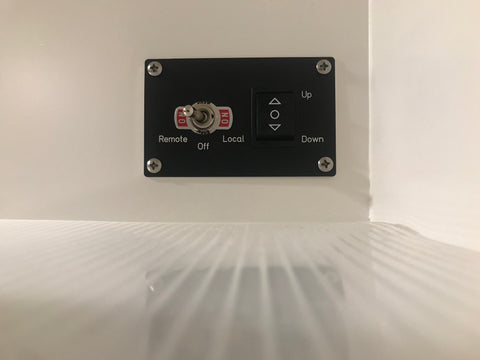
This switching panel was mounted inside an adjacent cabinet, providing easy access for mode selection while keeping all components hidden from view. The installer chose to leave the FIRGELLI control components exposed within the cabinet, appreciating their industrial aesthetic, though they could just as easily be concealed behind the false panel.


Power Supply Specifications
Linear actuators typically operate on 12V DC power, requiring conversion from standard 120V AC household current. This installation uses a 12V 30A power supply, which provides ample current capacity for two actuators operating simultaneously. When sizing power supplies, calculate the peak current draw of all actuators combined and add 20-30% margin. Undersized power supplies can cause voltage sag, resulting in sluggish actuator performance or premature component failure.
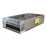
The power supply was mounted inside the cabinet where it remains concealed but accessible for service. Proper ventilation is essential—power supplies generate heat during operation, and adequate airflow prevents thermal shutdown or reduced lifespan.
Mechanical Installation and Mounting
Precise mechanical mounting is critical for smooth, quiet operation and long service life. The actuators in this installation were mounted using premium mounting brackets that were powder-coated matte black to match the kitchen hardware—a detail that elevates the overall finish quality.
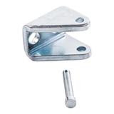
Bracket Placement and Geometry
Four MB1-P premium mounting brackets were used—one at each end of both actuators. These brackets allow the actuator to pivot as the panel moves through its arc, preventing binding that would occur if the actuators were rigidly mounted. The installer carefully calculated bracket positions to ensure the actuators remained within their recommended angular limits throughout the full range of motion.
When planning bracket locations, use cardboard templates to verify clearances and confirm that the actuators won't interfere with other cabinet components at any point in their travel. Test-fit everything before drilling permanent mounting holes.
TV Mounting Strategy
Rather than mounting the television to the panel or the cabinet back, this installation uses a concealed bracket that mounts the TV toward the front of the cabinet void, creating a floating appearance. This approach provides several benefits: it positions the screen closer to the viewer, improves the viewing angle, and simplifies access to the back of the television for cable management or future upgrades.

Cable Management and Connectivity
Modern smart TVs require multiple connections: power, HDMI inputs, ethernet or Wi-Fi, and possibly USB connections for streaming devices. This installation includes a false panel in front of the actuators that houses both 120V AC outlets and Cat6 ethernet jacks, providing all necessary connectivity while maintaining a clean appearance.
The false panel serves dual purposes: it conceals the actuator mechanisms from the front view and provides a convenient mounting surface for electrical outlets and data connections. All cables were dressed neatly and secured with cable ties to prevent interference with the moving panel and actuators.

Planning for future connectivity needs is worthwhile. Consider installing extra Cat6 runs or conduit that will accommodate additional cables if you later add streaming devices, gaming consoles, or upgrade to 8K-capable equipment requiring higher-bandwidth connections.
IoT Integration and Smart Home Compatibility
A significant advantage of this installation is its readiness for integration with home automation systems. The 12V DC control signals can interface with most smart home platforms through appropriate relay modules or controllers, enabling voice control, scheduled operation, or integration with other automated systems in the home.
For example, the hidden TV could be programmed to automatically reveal itself when motion is detected in the kitchen during morning hours, or to close when the home security system is armed. The wireless remote receiver could be replaced or supplemented with a Wi-Fi or Zigbee-enabled controller, bringing the system into the connected home ecosystem without requiring any changes to the mechanical installation.
Complete Parts List and Specifications
The following components were used in this installation. While specific product selections may vary based on your cabinet dimensions and preferences, this list provides a comprehensive starting point:
- Rocker Switch: Provides manual up/down control in local mode

- DPDT Sustaining Toggle Switch: Selects between remote and local control modes

- Optical Feedback Linear Actuators (2): 200 lb force rating, 12-inch stroke length
- AC to DC Power Supply: 12V 30A capacity
- 2-Channel Remote Control System: Wireless operation with transmitter and receiver

- Synchronous Control Board: Ensures parallel operation of both actuators
- MB1-P Premium Mounting Brackets (4): Powder-coated to match hardware finish
Installation Tips and Best Practices
Based on this successful installation, several practices emerge that can help ensure your project achieves similar results:
Work with your cabinet maker early: Integrating motorized components is far easier during initial construction than as a retrofit. Provide your cabinet maker with actuator dimensions and stroke requirements before finalizing designs.
Test before finishing: Fully wire and test the system before installing final trim, paint, or hardware. Making adjustments after finish work is completed risks damaging surfaces and requires additional touch-up work.
Consider weight distribution: Cabinet doors and panels can be heavier than expected, especially when constructed from hardwoods or fitted with thick decorative fronts. Weigh your panel and calculate the actual force required at your mounting geometry before selecting actuator force ratings.
Plan for service access: While the local control switch provides backup operation, ensure you can access the control components, power supply, and actuator connections without removing permanently attached trim or finish materials.
Use quality mounting hardware: The actuators will cycle thousands of times over the system's lifetime. Use grade-8 bolts, lock washers, and properly sized fasteners that won't loosen with repeated operation.
Alternative Applications and Variations
While this guide focuses on a kitchen hood installation, the same principles and components can be adapted for numerous other hidden TV applications throughout the home. TV lifts can be integrated into bedroom furniture, living room cabinets, outdoor entertainment centers, or even marine applications.
The actuator-based approach offers advantages over pre-manufactured TV lift mechanisms: greater customization, ability to accommodate non-standard TV sizes, and the flexibility to integrate with existing furniture or millwork. Track-style slide rails can enable side-to-side movement, while rotary actuators allow televisions to pivot for optimal viewing angles.
Conclusion
Building a hidden TV cabinet represents an intersection of traditional craftsmanship and modern automation technology. This Menlo Park installation demonstrates that with careful planning, appropriate component selection, and attention to mechanical and electrical details, DIYers and professional installers can create sophisticated concealment systems that rival factory-built solutions.
The key success factors include: working with your cabinet maker during the design phase, selecting feedback-equipped actuators with appropriate force and stroke specifications, implementing proper synchronization control, providing both wireless and hardwired control options, and maintaining the flexibility to integrate with future smart home systems. The result is a functional, aesthetically pleasing installation that enhances rather than compromises your kitchen design.
Frequently Asked Questions
What size linear actuator do I need for a hidden TV cabinet?
Actuator sizing depends on three factors: the weight of your cabinet door or panel, the mounting geometry, and desired speed. For typical cabinet doors weighing 10-30 pounds, actuators with 100-200 pound force ratings provide ample capacity with safety margin. The stroke length should equal or exceed the distance your panel needs to travel to fully clear the television viewing area—typically 8-16 inches for most installations. Feedback actuators are strongly recommended when using two actuators together, as they enable synchronized motion that prevents binding and uneven wear.
Can I retrofit linear actuators into an existing cabinet?
Retrofitting is possible but more challenging than integrating actuators during initial cabinet construction. You'll need sufficient depth behind the panel to accommodate the actuators in their fully retracted position, clearance for mounting brackets that allow pivoting motion, and access to route power and control wiring. Existing hinges may need reinforcement or replacement to handle the forces applied by actuators. If your cabinet wasn't designed with a void space for the TV, creating adequate depth may require modifying the cabinet box or reducing the TV size. Measure carefully and test-fit components with temporary mounting before drilling permanent holes.
How do I prevent two actuators from getting out of sync?
Standard actuators without feedback can drift out of synchronization due to minor differences in manufacturing tolerances, friction, or load distribution. The solution is using feedback actuators paired with a synchronous control board. The feedback sensors—typically optical encoders or Hall effect sensors—report actuator position throughout the stroke. The control board continuously monitors both actuators and adjusts their speed to maintain alignment within a few millimeters. This closed-loop control prevents the binding, twisting, and premature wear that occurs when one actuator extends faster than the other while driving a rigid panel.
What power supply capacity do I need for multiple actuators?
Calculate power requirements by adding the peak current draw of all actuators that may run simultaneously, then add 25-30% margin. Two standard actuators typically draw 3-6 amps each at peak load, suggesting a 12V 15A supply would be adequate. However, using a 12V 30A power supply ensures the system never operates near the supply's limit, reducing heat generation and extending component life. Undersized supplies cause voltage sag during actuation, resulting in slow movement and potential overheating. If your installation includes other 12V components like LED lighting, factor those loads into your calculations as well.
Can hidden TV systems integrate with smart home automation?
Yes, linear actuator systems are excellent candidates for smart home integration. The control signals are typically 12V DC, which can interface with most home automation platforms through appropriate relay modules, contact closure interfaces, or purpose-built controllers. Many installers use products like Shelly relay modules, Arduino-based controllers, or dedicated home automation interfaces to bridge between platforms like Control4, Crestron, or open-source systems like Home Assistant. Once integrated, you can create automation rules like revealing the TV when motion is detected, closing it at certain times, or voice-controlling it through Alexa or Google Assistant. The dual-mode control approach used in this installation—with both wireless remote and hardwired backup—provides flexibility for future upgrades without requiring rewiring.


