Designing a linear actuator system for rotating hatches, lids, or panels presents a unique engineering challenge. Unlike simple push-pull applications, rotational motion introduces complex geometric relationships between mounting positions, stroke lengths, and force requirements. The physics involves trigonometry, torque calculations, and spatial constraints that change throughout the actuator's range of motion.
For engineers and DIY builders alike, calculating these parameters manually is time-consuming and error-prone. A miscalculation can mean ordering an actuator with insufficient force, inadequate stroke length, or mounting positions that create mechanical interference. The iterative nature of design—testing different actuator specifications, adjusting mounting locations, and recalculating forces—can quickly become overwhelming when done by hand.
FIRGELLI's Linear Actuator Calculator eliminates this complexity by automating the trigonometric calculations and providing instant visual feedback. Whether you're designing a tonneau cover lift for a pickup truck, automating a wine cellar trapdoor, or creating a custom RV hatch system, this tool helps you identify compatible actuators and precise mounting coordinates in minutes rather than hours. This guide will walk you through every feature of the calculator and show you how to leverage it for successful project planning.
What is the Linear Actuator Calculator? It is a free FIRGELLI design tool that sizes a linear actuator and finds valid mounting coordinates for rotating hatches, lids, gates, and panels — automating the trigonometric calculations and providing instant visual feedback so you do not have to solve the geometry by hand.
Motion design starts with geometry, not force alone. On a rotating lid, the actuator's mechanical advantage changes through every degree of travel, and the worst-case force lives in the middle of the stroke — not at full open.
"On a rotating hatch, peak force almost never lands where people expect it. It lands somewhere in the middle of the travel, where the actuator angle is at its worst. Size the actuator for that point, not for the easy part of the stroke." — Robbie Dickson, Founder and Chief Engineer of FIRGELLI Automations
What does the Linear Actuator Calculator do for your project?
The Linear Actuator Calculator is purpose-built for rotational applications where a linear actuator causes angular motion about a fixed pivot point or hinge. It solves the fundamental question every builder faces: "Will this actuator work in my specific geometry, and where exactly should I mount it?"
The calculator performs several critical functions simultaneously. First, it calculates the required stroke length based on your dimensional inputs and desired opening angle. Second, it determines the minimum force needed at various points in the rotation cycle, accounting for the changing mechanical advantage as the lid opens. Third, and perhaps most valuable, it identifies all feasible mounting positions that satisfy both geometric constraints and force requirements.
Beyond simple hatch applications, this tool applies to any scenario involving rotational motion: electric gate openers, adjustable solar panel mounts, automated window systems, pop-up camper roofs, hood lifts, and custom furniture with moving components. The key requirement is that your application involves rotating an object around a fixed hinge point using linear actuation.
For applications that don't involve rotation—such as straight-line pushing, sliding mechanisms, or vertical lifting—different calculation methods apply. In those cases, force requirements are more straightforward but still critical to determine correctly before selecting an actuator.
What input dimensions does the calculator need?
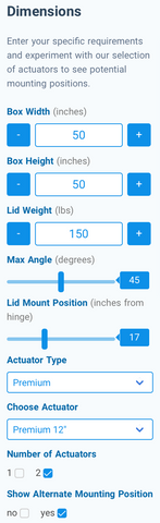
The left-hand panel of the calculator contains all the dimensional inputs that define your specific application. Each parameter plays a distinct role in determining which actuators will work and where they can be mounted. Understanding these inputs is crucial for accurate results.
Box Width Specification
Box width represents the horizontal distance available for actuator mounting, measured in inches. In most applications, this corresponds to the width of the hatch or lid itself, but it may differ if you have additional mounting space beyond the lid's edges. This dimension directly limits the maximum stroke length your actuator can have, since the actuator must fit within this space when fully retracted.
For pickup truck tonneau covers, box width typically matches the truck bed width. For trapdoors, it's the opening dimension parallel to the hinge. Consider any obstructions or mounting points that might further constrain this dimension in practice.
Box Height Specification
Box height defines the vertical clearance beneath your hatch, measured in inches from the hinge level to the lowest point of the closed enclosure. This parameter becomes critically important in space-constrained applications like tonneau covers, where only a few inches of clearance exist. The actuator's retracted length must fit within this height when the lid is closed.
In applications with generous clearance—wine cellar trapdoors, outdoor storage boxes, or cellar hatches—box height is less restrictive. However, accurately measuring this dimension prevents interference issues and ensures the actuator has adequate mounting space in both extended and retracted positions.
Lid Weight Parameter
Lid weight is the total mass of the rotating component, expressed in pounds. This is perhaps the most critical input for force calculations, as it directly determines the torque your actuator system must overcome. Be thorough when measuring—include the weight of the lid itself, any attached hardware, weather stripping, locks, or decorative elements.
For precise applications, weigh the lid on a scale before installation. For estimation purposes, calculate volume and multiply by material density: plywood averages 35 pounds per cubic foot, aluminum about 170 pounds per cubic foot, and steel roughly 490 pounds per cubic foot. Always round up slightly to account for hardware and provide a safety margin.
Table 1 — Common Lid Material Densities (for weight estimation)
| Material | Density (lb/ft³) |
|---|---|
| Plywood | 35 |
| Aluminum | 170 |
| Steel | 490 |
Note: Round up to account for hardware, fasteners, weatherstripping, and locks.
Maximum Angle Setting
The maximum angle parameter defines how far your lid will open, ranging from 0 degrees (fully closed) to 90 degrees (perpendicular to the base). This seemingly simple input has profound effects on force requirements and mounting feasibility. Peak force typically occurs at specific angles depending on geometry—often between 30 and 60 degrees—not necessarily at the fully open position.
Common angles include 45 degrees for space-efficient access, 60 degrees for comfortable clearance, 75 degrees for maximum access, and 90 degrees for full vertical opening. Higher angles generally require longer stroke lengths and may increase force requirements during the middle of the rotation cycle.
Lid Mount Position
Lid mount position specifies where along the lid the actuator attaches, measured in inches from the hinge line. This distance creates a moment arm that affects both the force required and the stroke length needed. Mounting farther from the hinge reduces the force requirement due to improved mechanical advantage but increases the required stroke length.
In some applications, lid construction or reinforcement limits where you can mount the actuator. Solid mounting points are essential—attaching to unsupported thin material will cause failure. If your design is flexible, the calculator allows you to experiment with different positions to find the optimal balance between force requirements and stroke length.
Actuator Type Selection
FIRGELLI manufactures several distinct actuator types, each optimized for different applications. The calculator includes our major product lines: Premium, Classic, Bullet, Industrial, Track, and Feedback series. Each type has unique characteristics regarding speed, force capacity, mounting options, and features.
Feedback actuators provide position sensing for synchronized multi-actuator systems or precise positioning requirements. Track actuators offer compact installation with protected components. Industrial actuators deliver higher force ratings and IP66 environmental protection. Bullet actuators provide fast speed for lightweight applications.
Table 2 — FIRGELLI Actuator Type Selection Guide
| Type | Best For | Notable Feature |
|---|---|---|
| Premium | General-purpose hatch and lid automation | Balanced speed and force |
| Classic | Cost-sensitive light/medium-duty builds | Standard performance |
| Bullet | Lightweight applications needing speed | Fast extension/retraction |
| Industrial | Outdoor, marine, dusty, or high-load installations | IP66 rating (per IEC 60529), higher force capacity |
| Track | Space-constrained installations | Compact profile, protected components |
| Feedback | Synchronized multi-actuator systems, precise positioning | Built-in position sensor |
If you're uncertain which type suits your needs, use the calculator to test multiple types. The results will reveal which actuator families can meet your specifications and which cannot generate sufficient force or stroke length.
Stroke Length Selection
After selecting an actuator type, you choose a specific model with a particular stroke length. Available strokes vary by actuator type but commonly range from 2 inches to 20 inches, with some industrial models offering up to 60 inches. The calculator instantly shows whether the selected stroke length works for your geometry.
Don't assume you need to know the correct stroke length before using the calculator—that's what the tool calculates for you. Start with a mid-range stroke length, then try shorter or longer options to see how mounting positions and force requirements change. This iterative approach often reveals optimal solutions you might not have considered.
Number of Actuators
The calculator supports either single or dual-actuator configurations. For any application wider than about 12 inches, two actuators mounted symmetrically on either side of the hatch are strongly recommended. Dual actuators provide balanced force distribution, prevent twisting loads, reduce stress on hinges, and create more stable motion.
Single-actuator configurations should only be used when the actuator is mounted along the centerline of the hatch. Pushing from one side creates lateral loads on hinges and can cause binding, warping, or premature failure. When you select two actuators in the calculator, force requirements are automatically divided between them, giving you the per-actuator force specification.
How do you interpret the calculator's visual diagram?
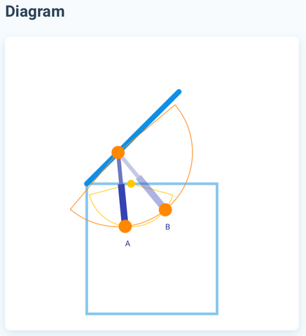
The central diagram provides an intuitive visual representation of your application, showing the box profile, lid position, and actuator mounting geometry. This graphical feedback is invaluable for understanding how your inputs translate into physical reality and for spotting potential issues before installation.
The diagram displays your box as a scaled rectangle with dimensions matching your inputs. The lid appears as a line segment attached at the hinge point, rotated to your specified maximum angle. Scale is proportional, so you can visually assess whether your design looks geometrically reasonable.
Understanding Mounting Position Indicators
Two colored dots appear on the diagram representing actuator mounting points. The orange dot shows where the actuator attaches to the lid at maximum opening. The yellow dot indicates the base mounting point on the box or frame. These positions represent one feasible mounting configuration that satisfies your specifications.
Arcs extending from each dot visualize the actuator's reach in extended and retracted states. The arc from the orange dot represents the actuator's minimum length (retracted), while the arc from the yellow dot represents the maximum length (extended). These arcs must intersect for a viable mounting solution to exist—if they don't overlap, no mounting position will work with the selected actuator.
Viewing Multiple Mounting Solutions
Most applications have multiple valid mounting positions that satisfy force and geometry requirements. By default, the calculator shows the primary solution, but enabling "Show Alternate Mounting Positions" reveals all feasible options. Each alternative appears as a different actuator position on the diagram, labeled alphabetically.
Having multiple options is valuable because practical considerations may make certain positions preferable. One mounting location might align better with existing structure, avoid obstructions, provide better access for installation, or create more favorable force angles. Review all options before finalizing your design.
How do you read the calculator's results?
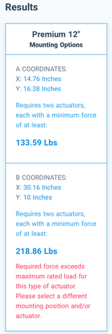
The results panel on the right side of the calculator presents the critical specifications you need for implementation: exact mounting coordinates and minimum force requirements for each feasible configuration. Understanding how to interpret these results ensures successful actuator selection and installation.
Mounting Coordinates Explained
Mounting coordinates are provided as XY pairs measured in inches from the hinge point as the origin. The X coordinate represents horizontal distance from the hinge along the base. The Y coordinate represents vertical distance below the hinge line. These coordinates tell you precisely where to position your mounting brackets on the frame or box.
For the lid attachment point, the calculator already incorporates your specified lid mount position. You only need to measure that distance along the lid from the hinge and install the bracket perpendicular to the lid surface at that point.
When multiple mounting options are available, coordinates are listed for positions A, B, C, etc. Each set represents a complete solution with its own force requirement. Transfer these measurements carefully during installation—precision in mounting position directly affects actuator performance and longevity.
Force Requirements Analysis
Below each mounting coordinate set, the calculator displays the minimum force required from each actuator to open the lid. This is not the actuator's rated force—it's the calculated force demand your application places on the actuator at that mounting position. The selected actuator's maximum force must exceed this minimum requirement.
Force requirements vary significantly between different mounting positions. Positions closer to the hinge require more force due to reduced mechanical advantage. Positions farther from the hinge reduce force demands but require longer stroke lengths. The calculator accounts for the worst-case force requirement throughout the entire rotation cycle, not just at one angle.
Understanding Error Indicators
When a mounting position's force requirement exceeds the selected actuator's capacity, red error text appears in the results window. This immediately identifies configurations that won't work. If all mounting positions show errors, the selected actuator is underpowered for your application.
Several strategies can resolve force errors. First, select an actuator with higher force capacity within the same product family. Second, adjust the lid mount position to improve mechanical advantage. Third, increase the number of actuators from one to two, halving the per-actuator force requirement. Fourth, if design flexibility permits, reduce lid weight or maximum opening angle.
Optimization Strategies
The calculator enables rapid iteration to optimize your design. If a 12-inch stroke actuator works but barely meets force requirements, try a 14-inch or 16-inch stroke—longer actuators often provide better mounting positions with more favorable force angles. If you're limited to a specific actuator type by budget or features, adjust dimensional parameters to find a workable configuration.
Balance between force capacity and stroke length is key. An actuator with 500 lbs force and 8-inch stroke might work better than a 200 lb force actuator with 12-inch stroke, depending on geometry. The calculator lets you test these trade-offs in seconds rather than working through manual calculations.
How does the calculator recommend a product?
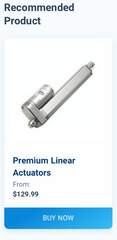
Once you've identified a compatible actuator and mounting configuration, the recommended product window displays the specific model that meets your requirements. This panel provides quick access to detailed specifications, pricing, and ordering information through a direct link to the product page.
Before finalizing your selection, review the actuator's full specifications on the product page. Confirm voltage compatibility with your power system—most FIRGELLI actuators operate on 12V DC, but some applications may require 24V models. Verify speed specifications to ensure the opening/closing cycle matches your expectations. Check IP rating if the installation will be exposed to weather or moisture.
Consider accessories you'll need for a complete system. Most installations require a control box for direction control and position limits. Power supplies must deliver adequate amperage for your actuator's specifications, typically 2-5 amps depending on model and load. Remote controls add convenience for frequently accessed hatches.
What advanced techniques get the most from the calculator?
Beyond basic calculator usage, several advanced techniques can help you extract maximum value from this tool and ensure project success.
Multi-Actuator Synchronization
When using two actuators in parallel, synchronization prevents uneven loading and binding. Feedback actuators with built-in position sensors enable electronic synchronization through compatible controllers. For applications without feedback, mechanical synchronization through rigid connecting rods or careful load balancing maintains alignment.
The calculator assumes both actuators share the load equally, which requires identical mounting positions on each side. Asymmetric mounting or uneven weight distribution can cause one actuator to work harder than the other, potentially leading to premature failure.
Safety Factor Considerations
The calculator provides minimum force requirements, but engineering best practice calls for safety factors. For static loads with well-defined weights, a 1.5x safety factor is reasonable. For dynamic loads, vibration, or uncertain weights, consider 2x or higher. This extra capacity accounts for friction in hinges, binding during motion, manufacturing tolerances, and long-term performance degradation.
If the calculator shows you need 150 lbs of force, selecting a 200-250 lb actuator provides appropriate margin. This prevents operating the actuator at maximum capacity, which reduces noise, heat generation, and mechanical stress, significantly extending service life.
Environmental Considerations
Outdoor installations face temperature extremes, moisture, dust, and UV exposure. Standard actuators typically operate from -20°C to +65°C, but performance degrades at temperature extremes. Industrial actuators with IP66 ratings resist water ingress and are suitable for exposed installations. For extreme environments, consider enclosures or weather boots to protect actuator components.
Salt exposure in marine environments or road spray requires corrosion-resistant materials. Stainless steel actuator rods and protective coatings extend life in these conditions. Regular maintenance—cleaning and lubricating pivot points—prevents premature failure in harsh environments.
Shock Load Management
The calculator assumes smooth, controlled motion. Sudden starts, stops, or external impacts create shock loads that can damage actuators. Soft-start controllers reduce current gradually to minimize mechanical shock. Limit switches prevent over-extension that could damage internal components. For applications where external forces might slam the lid (wind gusts, accidental impact), consider gas springs or mechanical stops to absorb energy.
How do you troubleshoot common calculator issues?
If the calculator shows no viable mounting positions or all positions exceed force capacity, several systematic approaches can resolve the issue.
No Feasible Mounting Solutions
When mounting arcs don't intersect on the diagram, the selected actuator's stroke length is incompatible with your geometry. Try the following adjustments: increase stroke length to the next available size, move the lid mount position farther from the hinge, reduce maximum opening angle, or consider a different actuator type with more stroke options.
Extremely constrained spaces may require creative mounting solutions. Some applications benefit from offset mounting using mounting brackets with extended arms. Others may need design modifications to create adequate space for actuator travel.
Force Requirements Too High
If all mounting positions show force errors, the load exceeds the actuator's capacity. Solutions include: selecting a higher force actuator model, moving the lid mount position farther from the hinge to improve mechanical advantage, reducing lid weight through material substitution or design changes, decreasing maximum opening angle if full 90-degree opening isn't necessary, or adding a second actuator to share the load.
Remember that force requirements peak at specific angles during rotation. Even if the calculator shows marginal results, that force demand occurs throughout the range of motion. Don't select an actuator that barely meets requirements—it will struggle and fail prematurely.
Physical Interference Concerns
The calculator validates geometry mathematically but cannot account for physical obstructions like frame members, adjacent equipment, or irregular lid shapes. After identifying mounting coordinates, visualize the actuator's path throughout its travel range. Ensure no collision occurs between the actuator body and surrounding structures at any angle.
Actuator body diameter varies by model, typically ranging from 1.5 to 3 inches. Factor in this clearance when planning installations in tight spaces. Some actuator types, like track actuators, offer more compact profiles for space-constrained applications.
What do real-world calculator examples look like?
Understanding how the calculator applies to specific scenarios helps clarify its practical value across diverse projects.
Truck Tonneau Cover Automation
A pickup truck bed measures 60 inches wide with only 4 inches of clearance beneath a hard tonneau cover. The aluminum cover weighs 45 pounds and should open to 75 degrees for bed access. With box width set to 60 inches, box height at 4 inches, lid weight 45 lbs, max angle 75 degrees, and lid mount position at 45 inches from the hinge, the calculator might recommend two 8-inch stroke actuators with 150 lb force capacity mounted at specific coordinates on each side.
The shallow box height constrains actuator selection to compact models that retract to under 4 inches. The calculator eliminates incompatible options automatically, saving hours of manual verification. Using two actuators prevents the heavy cover from twisting during operation.
Wine Cellar Trapdoor
A wine cellar access hatch measures 36 inches square, constructed from heavy oak and hardware totaling 60 pounds. The space beneath allows 24 inches of clearance. Opening to 90 degrees provides comfortable stairway access. With generous space, multiple actuator configurations work—a 12-inch stroke with mounting 24 inches from the hinge requires approximately 180 lbs force, while a 16-inch stroke mounted 30 inches from the hinge requires only 120 lbs force.
The calculator reveals this trade-off, allowing the builder to select based on available actuators and preferred mounting positions. The structural lid permits flexible mounting locations, and the calculator identifies the most mechanically efficient options.
Outdoor Storage Box
A weatherproof deck storage box has a 48-inch wide lid weighing 35 pounds with 18 inches of internal clearance. Opening to 60 degrees provides adequate access while preventing the lid from catching wind. Two 10-inch industrial actuators with IP66 rating resist weather exposure. The calculator identifies mounting positions that keep actuators clear of stored items while maintaining adequate force throughout the opening cycle.
For this outdoor application, environmental protection is critical. The calculator helps select actuators with appropriate force capacity, but the builder must also verify IP rating and corrosion resistance specifications on the product page.
What are common mistakes when using the Linear Actuator Calculator?
Most calculator missteps are not math errors — they are input or interpretation errors. Watch for these five:
- Underestimating lid weight. Skipping hardware, weatherstripping, locks, or decorative trim leads to under-sized actuators. Weigh the complete lid assembly, or calculate volume × density and round up.
- Sizing right at the calculated minimum force. The calculator reports the minimum required force, not a recommendation. Apply a 1.5x safety factor for static loads and 2x or higher for dynamic loads, wind, or uncertain weights.
- Specifying a single actuator on a wide hatch. Anything wider than roughly 12 inches needs two actuators mounted symmetrically; otherwise the hinges absorb a twisting load and bind.
- Ignoring physical interference. The calculator validates geometry but does not see frame members, latches, gas struts, or stored items. After picking a mounting position, sweep the actuator body through its full travel mentally (or in CAD) and check for collisions.
- Forgetting the environment. Box dimensions and lid weight do not change with weather, but actuator selection does. Confirm IP rating (per IEC 60529), temperature range, and corrosion resistance on the product page before ordering.
How can you verify the calculator output is reasonable?
Trust the math, but cross-check it. Five sanity checks catch the majority of input errors before you order parts:
- Sanity-check the moment arm. Roughly, required force ≈ (lid weight × distance from hinge to center of gravity) ÷ (lid mount distance from hinge), at the worst angle. If the calculator output is wildly off this ballpark, recheck your inputs.
- Confirm the retracted length physically fits. Stroke length plus the actuator's collapsed body must be shorter than your box height. If the diagram shows the actuator extending below the closed lid, the geometry is wrong.
- Compare against the worked examples. A 60-inch tonneau cover at 45 lbs and 75° lands around 150 lb per actuator with an 8-inch stroke. If your similar-sized application returns wildly different numbers, an input dimension is likely wrong.
- Verify mounting position improves mechanical advantage as expected. Moving the lid mount farther from the hinge should reduce force and increase required stroke. If results move the opposite direction, an input was entered in the wrong field.
- Build a paper or CAD mockup before ordering. Print the diagram to scale and trace the actuator path through 0° to max angle. This catches interference and angle issues the calculator cannot see.
How does the actuator integrate with control systems?
After selecting the right actuator through the calculator, integration with control electronics completes your automation system. FIRGELLI offers several control options depending on application complexity and desired features.
Basic control requires only a DPDT switch to reverse actuator polarity for extension and retraction. For safety and limit control, dedicated control boxes provide built-in limit switches, preventing over-extension. Wireless remote controls add convenience for frequently accessed hatches.
Advanced applications benefit from programmable controllers. Arduino-based systems enable custom logic, sensor integration, and automated operation based on environmental conditions. Feedback actuators report position data for precise control and multi-actuator synchronization.
For home automation integration, relay-based control allows actuators to interface with smart home systems like Home Assistant, SmartThings, or custom automation platforms. Proper power supply sizing ensures reliable operation—most 12V actuators draw 2-5 amps under load, requiring power supplies rated for peak current draw.
Conclusion
The Linear Actuator Calculator transforms complex rotational motion design from hours of manual trigonometry into minutes of interactive exploration. By automating force calculations, stroke length requirements, and mounting position geometry, it eliminates guesswork and reduces the risk of costly mistakes in actuator selection.
Whether you're an engineer designing commercial equipment or a DIY builder automating a personal project, this tool provides the technical precision needed for successful implementation. The visual feedback helps you understand how dimensional changes affect feasibility, while multiple mounting options give you flexibility to work around practical constraints.
With the calculator's guidance, proper actuator selection, and attention to installation details, you can create reliable, efficient motion control systems for hatches, lids, gates, and countless other rotating applications. The combination of precise calculations and FIRGELLI's extensive linear actuator product line ensures you'll find a solution that meets both your technical requirements and practical needs.
Frequently Asked Questions
How accurate is the Linear Actuator Calculator?
The calculator uses precise trigonometric formulas to model rotational mechanics, providing mathematically accurate results for the geometry you input. Accuracy depends entirely on the precision of your measurements—box dimensions, lid weight, and hinge position. For best results, measure carefully using reliable tools. The calculator accounts for changing mechanical advantage throughout the rotation cycle and calculates peak force requirements, not just force at one position. While it cannot account for real-world factors like friction in hinges or binding in guides, applying appropriate safety factors (1.5-2x the calculated force) addresses these variables effectively.
Can I use one actuator instead of two for cost savings?
Single-actuator configurations are only appropriate when the actuator mounts along the exact centerline of the hatch, creating balanced forces on both sides. For hatches wider than 12-18 inches, mounting a single actuator off-center creates twisting forces that stress hinges, cause binding, and lead to premature failure. The calculator defaults to recommending two actuators for good reason—uneven loading damages both the actuator and the hatch structure. If cost is a concern, consider selecting two lower-force actuators rather than one high-force unit mounted off-center. The symmetric dual-actuator approach ensures smooth operation, longer component life, and reliable performance.
What if the calculated stroke length doesn't match available actuators?
When the ideal stroke length falls between available sizes, selecting the next longer stroke usually works with adjusted mounting positions. The calculator allows you to test different stroke lengths and see how mounting coordinates and force requirements change. Sometimes a longer actuator mounted slightly differently provides better mechanical advantage and lower force requirements. If no standard stroke length works within your constraints, you have several options: modify the lid mount position to accommodate available strokes, adjust the maximum opening angle, increase box dimensions if design flexibility permits, or consider custom actuator fabrication for specialized applications requiring non-standard specifications.
Why does force requirement change with mounting position?
Force requirements vary based on mechanical advantage, which depends on the angle between the actuator and the lid throughout rotation. Mounting closer to the hinge creates a shorter moment arm, requiring more force to generate equivalent torque. Mounting farther from the hinge improves mechanical advantage, reducing force requirements but increasing necessary stroke length. Additionally, the angle at which the actuator pushes changes throughout the rotation cycle—perpendicular angles provide maximum efficiency while shallow angles reduce effectiveness. The calculator evaluates force requirements at every point in the rotation and reports the maximum demand, ensuring the selected actuator can handle worst-case loading throughout the entire range of motion.
Can I use the calculator for outdoor installations with weather exposure?
The calculator determines force and geometry requirements regardless of environment, but environmental factors critically affect actuator selection. For outdoor applications, verify IP rating on the product page after using the calculator to identify compatible models. Standard actuators (typically IP54) resist light moisture but aren't suitable for direct weather exposure. Industrial actuators with IP66 ratings withstand heavy rain and dust, making them appropriate for exposed installations. (IP ratings are defined by IEC 60529.) Temperature extremes affect performance—standard actuators operate from -20°C to +65°C, but extreme cold can slow operation while extreme heat may trigger thermal protection. For marine or salt-spray environments, stainless steel actuator rods prevent corrosion. Factor in these environmental considerations when finalizing actuator selection after calculator analysis.
Do I need feedback actuators for my application?
Feedback actuators incorporate position sensors that report extension distance, enabling several advanced capabilities. You need feedback if your application requires: synchronizing multiple actuators electronically to prevent uneven motion, stopping at precise intermediate positions rather than just fully open or closed, integrating with automation systems that need position data, or creating user interfaces that display actuator position. For simple open/close applications controlled by limit switches without position monitoring requirements, standard actuators without feedback are sufficient and more cost-effective. The calculator works with both feedback and non-feedback actuators—select based on control system requirements rather than geometric compatibility, which the calculator addresses regardless of actuator features.
About the author. Robbie Dickson is the Founder and Chief Engineer of FIRGELLI Automations. He spent his early career as a mechanical engineer at Rolls-Royce, BMW, Isuzu, and Ford before founding FIRGELLI in 2002 to design and manufacture linear actuators and motion-control hardware. See Wikipedia for background.


