Wireless remote control systems offer unmatched convenience for operating linear actuators in applications ranging from home automation projects to industrial machinery. Whether you're building a motorized hatch, automated window system, or adjustable workstation, a 2-channel remote control system provides reliable wireless operation with extended range and simple setup. However, proper configuration and wiring are essential to ensure safe, reliable operation and prevent damage to both the control system and your actuators.
🎥 Video — How to control a linear actuator using a 2 channel remote control
This comprehensive guide covers everything you need to know about setting up and controlling linear actuators with a 2-channel remote control system. We'll walk through switching between momentary and latching control modes, programming multiple remotes, handling high-current applications, and safely wiring multiple actuators. Understanding these fundamentals will help you avoid common pitfalls like exceeding current ratings or improper relay implementation that can lead to system failure.
The FIRGELLI 2-channel remote control system is designed to work seamlessly with our Premium and Classic series actuators, providing up to 5 amps of switching capacity per channel. For higher force applications or multiple actuator setups, we'll show you how to implement relay-based circuits that protect your control electronics while delivering the power your project demands.
Understanding Momentary vs. Latching Control Modes
The 2-channel remote control system supports two distinct operating modes that determine how your actuator responds to button presses. Understanding the difference between these modes is crucial for selecting the right configuration for your application.
Momentary Mode Operation
By default, the remote system ships programmed in momentary mode. In this configuration, the linear actuator operates only while you actively hold down the remote button. As soon as you release the button, the actuator immediately stops moving. This mode provides precise control over actuator position, making it ideal for applications where you need to stop the actuator at specific points along its stroke rather than always traveling to full extension or retraction.
Momentary mode is particularly useful for adjustable furniture, camera positioning systems, or any application requiring frequent position changes. The operator maintains continuous control throughout the movement, allowing for real-time adjustments based on visual feedback or changing requirements.
Latching Mode Operation
In latching mode, a single button press initiates continuous movement until the actuator reaches its internal limit switch and automatically stops. This "set and forget" operation eliminates the need to hold the button during the entire stroke, which can be convenient for longer travel distances or applications where the actuator consistently moves between two fixed positions.
Latching mode works well for applications like automated hatches, pop-up TV lifts, or hidden compartment doors where you typically want full extension or retraction rather than intermediate positions. The actuator will continue moving until it hits its mechanical limit, ensuring consistent endpoint positioning every time.
Switching Between Momentary and Latching Modes
Changing the control mode requires a simple hardware adjustment on the receiver unit. The process takes only a few minutes and requires no special tools or technical expertise.
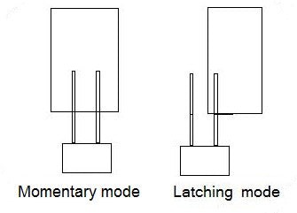
To switch modes, first locate the small black jumper block on the front of the receiver circuit board. This jumper consists of a plastic connector that bridges two pins. For momentary mode (the factory default), the jumper connects two adjacent pins. To change to latching mode, carefully remove the jumper and place it on just one pin instead of bridging both pins together. This stores the jumper safely while disabling the momentary function.
After adjusting the jumper position, you must power cycle the receiver for the change to take effect. Disconnect the power supply from the receiver unit completely, wait a few seconds, then reconnect it. This resets the microcontroller and loads the new configuration. Test the new mode by pressing a button on the remote and verifying the actuator behavior matches your expectations.
Programming Additional Remote Controls
The receiver can learn and respond to multiple remote transmitters, allowing you to control your actuators from different locations or provide remotes to multiple users. This flexibility is valuable in shared workspaces, multi-user equipment, or applications requiring control access from different areas.
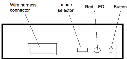
To program additional remotes, you'll need to open the receiver case to access the programming button on the circuit board. Press and hold this button until the red LED begins flashing—this typically takes 3-5 seconds. The flashing LED indicates the receiver has entered learning mode and is ready to accept new remote codes.
With the receiver in learning mode, press any button on the first remote you want to program. The LED will typically flash or change pattern to confirm it received the signal. Repeat this process for each additional remote, pressing one button on each unit. It's important to note that you must reprogram all remotes during this process, even if some were already paired with the receiver. The learning process overwrites the previous memory and creates a fresh list of authorized transmitters.
After programming all remotes, power cycle the receiver by disconnecting and reconnecting the power supply. This saves the new remote configurations to memory. Test each remote to verify all buttons function correctly. If any remote fails to operate, repeat the programming sequence—incomplete programming is usually the result of insufficient button press duration or interference during the learning process.
Handling High-Current Applications Above 5 Amps
The 2-channel remote control board has a maximum current rating of 5 amps per channel, making it directly compatible with most standard linear actuators including our Premium and Classic series. However, many high-force applications require actuators that draw significantly more current, potentially damaging the control electronics if connected directly.
Current Limitations and Actuator Compatibility
Our industrial actuators and heavy-duty models can draw up to 20 amps under load—four times the rated capacity of the remote control board. Connecting such an actuator directly to the control board will cause immediate and irreversible damage to the switching transistors, rendering the board inoperable. Even brief operation at excessive current can destroy semiconductor components, so it's critical to implement proper current isolation before applying power.
The damage occurs because the small switching transistors on the control board cannot dissipate the heat generated by high current flow. These components are sized for 5-amp maximum operation, and exceeding this limit causes rapid thermal failure. This isn't a flaw in the design—it's a trade-off that allows for compact, economical control boards suitable for the vast majority of applications.
Implementing Relay-Based Current Isolation
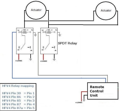
For high-current actuators, the solution is to use the remote control board as a low-power control signal that switches external relays, which in turn handle the high current to the actuator. This approach isolates the delicate control electronics from the heavy power circuits, protecting the remote receiver while enabling control of virtually any actuator regardless of current draw.
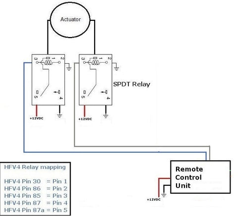
You'll need a pair of SPDT (Single Pole Double Throw) relays rated for at least 20 amps. Each relay controls one direction of actuator movement—one relay for extension, one for retraction. The remote control board energizes the relay coils with its low-current outputs, and the relay contacts switch the high-current power to the actuator. This configuration provides complete electrical isolation while maintaining full control functionality.
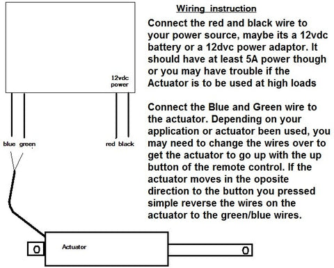
The wiring diagram above shows the proper connections. The remote receiver connects to the relay coils, while the actuator and main power supply connect only to the relay contacts. Never allow high-current actuator wiring to connect directly to the remote control board terminals. Optional wiring harnesses are available that simplify these connections and reduce the risk of wiring errors.
Controlling Multiple Linear Actuators Simultaneously
Many projects require two or more linear actuators to move in synchronized fashion—examples include dual-actuator lift systems, opposing hatch mechanisms, or symmetrical positioning systems. While it's tempting to simply wire multiple actuators in parallel to a single control board, this approach almost always exceeds the current rating and will damage the electronics.
Current Considerations for Multiple Actuators
Current draws are additive in parallel circuits. Two actuators that each draw 3 amps will pull a combined 6 amps from the control board—exceeding its 5-amp rating and causing potential failure. Even if individual actuators are within the current limit, connecting two or more together will likely exceed it. Never connect multiple actuators directly to the control board without implementing proper current isolation through relays.
The same relay-based approach used for high-current single actuators applies to multiple actuator systems. The relays handle the combined current of all actuators while the control board only drives the low-power relay coils. This configuration allows you to control multiple standard actuators or even multiple high-force units from a single 2-channel remote.
Power Supply Sizing for Multiple Actuators
Your power supply must provide sufficient current for all actuators operating simultaneously. Add up the current ratings of all actuators and select a power supply with at least 20% additional capacity to handle startup current spikes and provide a safety margin. For example, two 5-amp actuators require a power supply rated for at least 12 amps (2 × 5 × 1.2 = 12 amps).
Undersized power supplies will cause voltage drops under load, leading to sluggish actuator performance, overheating, and potential damage to both the power supply and actuators. In extreme cases, the power supply may enter thermal shutdown or fail completely. Always err on the side of oversizing—a larger power supply operating at partial capacity will run cooler, more efficiently, and more reliably than one operating at its maximum rating.
Synchronization Limitations
When multiple actuators share the same power supply and control signals, they will move together but not necessarily at exactly the same speed. Manufacturing tolerances, mechanical loading differences, and minor variations in friction all contribute to slight speed differences between units. For most applications, these variations are minimal and imperceptible, but precision applications requiring exact synchronization may need more sophisticated control systems with feedback actuators and position sensing.
The speed variations typically amount to only a few percent difference, meaning actuators will reach their endpoints within seconds of each other even on long strokes. This level of synchronization is perfectly adequate for furniture, hatches, adjustable platforms, and similar applications. For applications requiring tighter synchronization, consider using actuators with built-in position feedback and a control system that actively compensates for position differences.
Ultra-High-Current Applications with Multiple Heavy-Duty Actuators
Some demanding applications require multiple high-force industrial actuators operating simultaneously. For example, a dual-actuator heavy-duty lift system using two 20-amp actuators would draw a combined 40 amps per direction—twice the rating of standard 20-amp relays. This scenario requires additional current distribution to prevent relay failure.
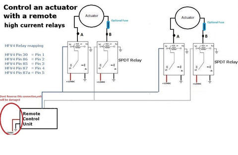
The solution is to use dedicated relay pairs for each actuator rather than routing all current through a single set of relays. Each actuator gets its own pair of 20-amp relays, but all relay coils connect in parallel to the remote control board outputs. This way, the control board still only drives the low-current relay coils, but each relay only carries the current for its associated actuator—staying within the relay's rating.
Power supply considerations become critical in these high-power configurations. Two 20-amp actuators require a 12V supply capable of delivering at least 40 amps continuously, with headroom for startup surges. This might be a single large 12V 50-amp supply, or you could use two separate 12V 25-amp supplies with one dedicated to each relay/actuator pair. Separate supplies can simplify wiring and improve reliability by isolating each actuator's power circuit.
Always use appropriately sized wire for high-current applications. Wire gauge must be sufficient to carry the current without excessive voltage drop or heating. For 20-amp circuits, use minimum 12 AWG wire; for 40-amp circuits, use 8 AWG or larger. Keep wire runs as short as practical to minimize resistance losses, and ensure all connections are tight and secure—loose connections create resistance, heat, and potential fire hazards.
Troubleshooting Common Remote Control Issues
While the 2-channel remote system is generally reliable, occasional issues can occur. Understanding common problems and their solutions will help you quickly diagnose and resolve operational difficulties.
Remote Not Responding
If the remote fails to activate the actuator, first check the obvious: verify the remote has a fresh battery and the receiver has power. The receiver's LED indicator should illuminate when powered. If the LED is off, check your power supply connections and verify the supply is outputting correct voltage.
If power is present but the remote doesn't work, the remote may need reprogramming. Follow the programming procedure described earlier to re-pair the remote with the receiver. Environmental interference can occasionally corrupt the stored codes, requiring a fresh programming cycle.
Actuator Runs Continuously or Wrong Direction
Continuous operation when you expect momentary control indicates the jumper is set for latching mode. Check the jumper position and mode setting. If the actuator moves in the opposite direction from expected, the actuator lead wires are reversed. Simply swap the two actuator wire connections at the remote receiver or relay contacts to correct the direction.
Intermittent Operation or Short Range
If the remote only works at very short distances or operates erratically, the battery may be weak even if not completely dead. Replace the battery and retest. Metal enclosures around the receiver can also shield the antenna and reduce range—ensure the receiver antenna (if external) is positioned for good signal reception and not buried inside a metal housing.
Large motors, fluorescent lights, and other electrical equipment can generate RF interference. If possible, relocate the receiver away from potential interference sources. In severe cases, you may need to add ferrite beads to power cables or implement shielded enclosures.
Safety and Best Practices
Proper installation practices ensure reliable operation and prevent safety hazards. Always disconnect power before making wiring changes. Double-check all connections before applying power—reversed polarity or short circuits can immediately damage components.
Use appropriate wire sizing and strain relief. Moving actuators can flex and stress wiring over time, potentially causing fatigue failures. Provide adequate slack in wiring to accommodate actuator movement, and use cable management to prevent snagging or pinching.
Consider implementing emergency stop functionality in applications where unexpected actuator movement could cause injury or equipment damage. While the 2-channel remote provides basic control, more complex systems may benefit from additional safety interlocks, limit switches, or obstruction detection.
Mount relays in accessible locations with adequate ventilation. Relays generate heat during operation, and proper airflow prevents thermal stress and extends relay life. Use mounting brackets or DIN rail mounting systems to secure components properly.
Conclusion
The 2-channel remote control system provides a versatile, reliable solution for wireless linear actuator control. By understanding mode settings, proper current management through relays, and correct wiring practices for single or multiple actuator configurations, you can implement professional-quality remote control in virtually any application. The key to success lies in respecting current limitations, implementing appropriate relay isolation when needed, and following proven wiring practices.
Whether you're building a simple single-actuator project or a complex multi-actuator system, the principles outlined in this guide will help you achieve safe, reliable operation. Take time to plan your wiring, select appropriately rated components, and test thoroughly before putting your system into service. With proper implementation, remote-controlled actuators provide years of convenient, trouble-free operation.
Frequently Asked Questions
How many remotes can be programmed to work with a single receiver?
The FIRGELLI 2-channel receiver can typically store codes for 4-6 remote transmitters simultaneously. However, all remotes must be reprogrammed together during the same programming session—you cannot add individual remotes to the existing list without reprogramming all units. When you enter programming mode, the receiver clears its memory and creates a fresh list of authorized remotes. For applications requiring more than 6 remotes, consider using multiple receiver units controlling the same relay circuit.
What is the maximum range of the 2-channel remote control system?
Under optimal conditions with clear line-of-sight, the remote typically achieves ranges of 50-100 feet or more. However, actual range varies significantly based on environmental factors. Metal buildings, concrete walls, and RF interference from other equipment can substantially reduce effective range. For best results, position the receiver with its antenna in a location that minimizes obstacles between the remote and receiver. If you require longer range, external antenna options or alternative control systems may be necessary.
Can I control two separate actuators independently with different remotes?
The 2-channel system allows control of two functions (typically extend and retract) for actuators that move together. If you need to control two actuators completely independently—moving one without affecting the other—you'll need a 4-channel remote control system. The 4-channel system provides two independent channels, each with extend/retract control, allowing separate operation of two actuators or actuator groups.
What happens if I accidentally exceed the 5-amp current rating?
Exceeding the current rating typically causes immediate and permanent damage to the switching transistors on the control board. These components will fail in a short-circuit condition, causing the actuator to either run continuously or not operate at all. The board cannot be repaired and must be replaced. Always verify actuator current draw specifications and implement relay isolation for any actuator rated above 4 amps to provide a safety margin below the 5-amp maximum.
Do I need separate power supplies for the receiver and actuators when using relays?
No, a single appropriately sized power supply can power both the receiver and actuators when using relay isolation. The relays electrically isolate the control circuits from the high-current actuator circuits, but they can share a common power source. Ensure your power supply is rated for the combined current draw of all actuators plus a safety margin. However, in ultra-high-current applications (40+ amps), using separate supplies for different actuator circuits can simplify wiring and improve reliability.
Why don't my multiple actuators move at exactly the same speed?
Slight speed variations between actuators are normal and result from manufacturing tolerances in motor windings, gearbox efficiency, mechanical loading differences, and friction variations. These factors cause each actuator to draw slightly different current and achieve slightly different speeds even when powered identically. For most applications, these variations are negligible—typically only a few percent difference. If your application requires precise synchronization, consider using feedback actuators with position sensing and a control system that actively adjusts for position differences.


