Designing a filter, power stage, or RF circuit often comes down to hitting a precise inductance value — and series inductors are one of the most direct ways to get there. Use this Series Inductors Calculator to calculate total equivalent inductance using individual inductor values, mutual inductance, coupling coefficient, energy storage, and inductive reactance. Getting this right matters in filter design, switch-mode power supplies, and RF impedance matching where even a small inductance error shifts your resonant frequency or ruins rolloff. This page includes the governing formulas, a worked multi-stage LC filter example, theory on mutual coupling and saturation, and a full FAQ.
What is series inductance?
Series inductance is the total inductance you get when two or more inductors are connected end-to-end in the same current path. Without magnetic coupling between them, the total is simply the sum of all individual values.
Simple Explanation
Think of inductors in series like water pipes connected end-to-end — the same flow (current) passes through each one, and the total resistance to change in that flow adds up. If 2 inductors are close enough that their magnetic fields overlap, they can either push each other (aiding) or fight each other (opposing), which changes the total beyond a simple sum.
📐 Browse all 1000+ Interactive Calculators
Series Inductors Circuit Diagram

Series Inductors Calculator
How to Use This Calculator
- Select your calculation mode from the dropdown — total inductance, mutual inductance, required inductance, parallel equivalent, energy storage, or series reactance.
- Enter the number of inductors (for total mode) or the specific inductance, mutual inductance, current, or frequency values required by the selected mode.
- For the two-inductor mutual mode, also select whether the flux is aiding or opposing.
- Click Calculate to see your result.
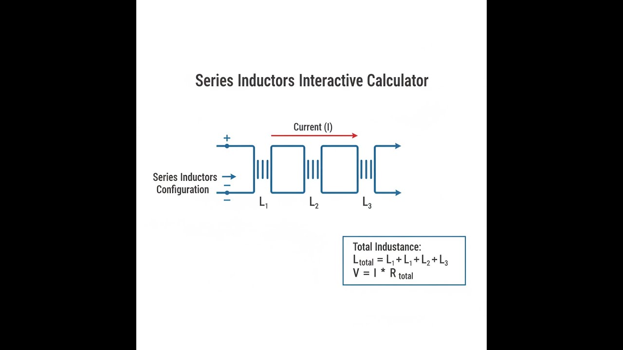
Series Inductors Interactive Calculator
Visualize how multiple inductors combine in series to achieve target inductance values. Watch magnetic field interactions and see how mutual coupling affects total inductance in real-time.
TOTAL INDUCTANCE
100 mH
STORED ENERGY
0.20 J
REACTANCE @ 1kHz
628 Ω
FIRGELLI Automations — Interactive Engineering Calculators
Governing Equations
Use the formula below to calculate total series inductance.
Series Inductance (Without Mutual Coupling)
Ltotal = L1 + L2 + L3 + ... + Ln
Two Inductors with Mutual Inductance
Ltotal = L1 + L2 ± 2M
+ when flux is aiding, − when flux is opposing
Coupling Coefficient
k = M / √(L1L2)
where 0 ≤ k ≤ 1
Energy Storage
E = ½ L I²
Inductive Reactance
XL = ωL = 2πfL
Variable Definitions:
- Ltotal: Total series inductance (H, henries)
- L1, L2, Ln: Individual inductances (H)
- M: Mutual inductance between coils (H)
- k: Coupling coefficient (dimensionless, 0 to 1)
- E: Stored magnetic energy (J, joules)
- I: Current through inductors (A, amperes)
- XL: Inductive reactance (Ω, ohms)
- f: Frequency (Hz, hertz)
- ω: Angular frequency (rad/s)
Simple Example
3 inductors in series, no mutual coupling: L1 = 10 mH, L2 = 20 mH, L3 = 30 mH.
Ltotal = 10 + 20 + 30 = 60 mH.
At 1 kHz, inductive reactance XL = 2π × 1000 × 0.060 = 376.99 Ω.
Theory & Practical Applications
Fundamental Principles of Series Inductance
When inductors are connected in series, the total inductance is the sum of individual inductances, provided there is no magnetic coupling between them. This additive behavior arises because the same current flows through each inductor, and the voltage drops across each inductor add according to Kirchhoff's voltage law. The instantaneous voltage across an inductor is given by V = L(dI/dt), so for n series inductors with no mutual coupling, the total voltage becomes Vtotal = (L1 + L2 + ... + Ln)(dI/dt), yielding an equivalent inductance equal to the sum.
However, real-world inductor assemblies rarely achieve zero mutual coupling. When two inductors are placed in proximity, their magnetic fields interact through mutual inductance M, which can either increase or decrease the total inductance depending on the relative orientation of the windings. If the magnetic fluxes aid each other (series-aiding connection), the total inductance becomes Ltotal = L1 + L2 + 2M. Conversely, if the fluxes oppose (series-opposing), the total inductance reduces to Ltotal = L1 + L2 − 2M. This is critical in transformer design, where deliberate series-aiding or opposing configurations are used to control leakage inductance and voltage ratios.
Mutual Inductance and Coupling Coefficient
The coupling coefficient k quantifies how effectively two inductors are magnetically coupled, ranging from 0 (no coupling) to 1 (perfect coupling). For two inductors with self-inductances L1 and L2, the mutual inductance cannot exceed Mmax = √(L1L2). Air-core inductors typically exhibit k values between 0.1 and 0.5, while ferrite-core transformers can achieve k above 0.95. In precision filter design, even small mutual inductances (k = 0.05 to 0.1) can shift resonant frequencies by several percent, causing filter rolloff characteristics to deviate significantly from theoretical predictions. Multi-layer PCB inductors are particularly susceptible to unintended coupling when stacked vertically — a 1 nH mutual inductance at 2.4 GHz represents a reactance of 15 Ω, enough to detune an impedance-matched RF circuit.
The polarity marking (dot convention) on inductors indicates which terminal has the same instantaneous voltage polarity when flux is changing in the same direction. Connecting dot-to-dot produces series-aiding, while dot-to-non-dot produces series-opposing. In power electronics, series-aiding configurations are used in coupled inductors for interleaved buck converters, where the mutual inductance reduces ripple current by allowing flux cancellation between phases. Conversely, series-opposing connections are employed in common-mode chokes for EMI suppression, where differential-mode signals see minimal inductance while common-mode noise encounters high impedance.
Energy Storage and Current Distribution
The energy stored in a series inductor configuration is E = ½LtotalI², where I is the common current flowing through all inductors. Unlike parallel configurations where current divides, series inductors share the same current, meaning a single high-current surge affects all inductors simultaneously. This has significant implications for fault tolerance — if one inductor in a series chain saturates or fails open, the entire circuit path is interrupted. In high-power DC-DC converters operating at 50 A or more, the series connection of multiple smaller inductors (e.g., three 15 μH inductors instead of one 45 μH) improves thermal distribution and allows modular replacement, but requires careful attention to saturation currents.
If the individual inductors have saturation currents of 60 A but the application requires 50 A continuous, the design has minimal headroom — a 20% overload would push all inductors into saturation simultaneously. The energy release rate during switching events scales with L(dI/dt), so series inductors increase the inductive kick voltage proportionally. In flyback converter design, the primary-side inductance directly determines the peak voltage stress on the switching transistor during turn-off. A doubling of inductance from 100 μH to 200 μH increases the flyback voltage spike proportionally, potentially requiring MOSFETs with higher voltage ratings (e.g., 650V instead of 400V). This trade-off between inductance (which improves efficiency by reducing ripple) and voltage stress is fundamental to power supply topology selection.
Frequency-Dependent Behavior and Parasitic Effects
At high frequencies, the simple series inductance model breaks down due to parasitic capacitance between inductor turns. Each inductor has a self-resonant frequency (SRF) where the inductive reactance equals the capacitive reactance of the parasitic capacitance, causing the component to behave as a parallel LC resonator rather than a pure inductor. For a typical power inductor with 47 μH inductance and 15 pF parasitic capacitance, the SRF occurs at approximately 19 MHz. Above the SRF, the impedance magnitude decreases with frequency rather than increasing, rendering the inductor ineffective for filtering or energy storage.
When multiple inductors are connected in series, the overall SRF is generally lower than the individual SRFs because the total inductance increases while capacitance adds in series (reducing effective capacitance but not enough to compensate). Three series 10 μH inductors (30 μH total) typically have an SRF 10-15% lower than a single 30 μH inductor due to additional inter-component parasitic capacitances. In RF applications above 100 MHz, multilayer ceramic chip inductors are preferred over wirewound types specifically because their distributed capacitance is lower, pushing the SRF well into the GHz range.
Industrial Applications Across Sectors
In audio electronics, series inductors form the high-pass sections of passive crossover networks, protecting tweeters from low-frequency signals that could cause mechanical damage. A typical 2-way speaker crossover might use a 0.6 mH series inductor in the tweeter path to create a 12 dB/octave slope starting at 3.2 kHz. The inductor must maintain low DC resistance (typically under 0.5 Ω for 8 Ω speakers) to avoid power loss and maintain damping factor, while the core material must handle the peak AC flux without saturation — a consideration that becomes critical at sound levels above 100 dB SPL where instantaneous current swings can reach 3-4 A.
Power distribution systems employ series inductors (reactors) for current limiting during fault conditions. A 500 kVA substation transformer might include a 50 μH series reactor on the secondary side to limit the initial fault current to 10 kA RMS rather than the 30 kA prospective short-circuit current. The reactor's inductance must be precisely calculated — too high and voltage regulation suffers (excessive voltage drop under load), too low and circuit breakers cannot interrupt the fault within their rated time windows.
Automotive DC-DC converters use series-connected inductors in multiphase buck topologies to reduce input and output ripple. A 12V-to-1.2V converter supplying 150 A for ECU operation might use three 330 nH inductors operating 120° out of phase, effectively creating an equivalent ripple inductance of 990 nH at the third harmonic frequency (the dominant ripple component). The series connection ensures current sharing while the phase offset provides ripple cancellation — a technique that reduces output capacitor size and cost by 60-70% compared to single-phase designs. For more calculator tools like this, visit our engineering calculator hub.
Worked Example: Multi-Stage LC Filter Design
Consider designing a three-stage LC low-pass filter for a 24V, 10 A switch-mode power supply operating at 150 kHz switching frequency. The filter must attenuate conducted EMI by at least 60 dB at the fundamental switching frequency while maintaining less than 2% voltage ripple at full load. The output capacitance is fixed at 220 μF (three 68 μF low-ESR electrolytics in parallel), and we need to determine the required series inductance and verify saturation margins.
Step 1: Calculate Required Cutoff Frequency
For 60 dB attenuation at 150 kHz with a second-order filter (40 dB/decade), the cutoff frequency must be placed one decade below the switching frequency: fc = 150 kHz / 10 = 15 kHz. Using the LC filter cutoff formula fc = 1/(2π√(LC)), we solve for L:
L = 1 / [(2πfc)²C] = 1 / [(2π × 15000)² × 220 × 10⁻—] = 1 / [8.88 × 10⁹ × 2.2 × 10⁻⁴] = 1 / 1.954 × 10⁶ = 0.512 × 10⁻⁶ H = 512 nH
Step 2: Distribute Inductance Across Three Stages
For a three-stage Butterworth-aligned filter with optimal damping, the inductances are distributed in a 1:2:1 ratio. Total inductance needed: 512 nH, distributed as L1 = 128 nH, L2 = 256 nH, L3 = 128 nH. This provides the steepest rolloff without excessive peaking at the cutoff frequency.
Step 3: Verify Saturation Current Requirements
Each inductor must handle 10 A continuous plus the peak AC ripple current. The ripple current amplitude at the first stage is approximately ΔI = (Vin × D × (1−D)) / (L × fsw), where D is the duty cycle. For a 24V supply, assuming a buck converter with 50% duty cycle: ΔI = (24 × 0.5 × 0.5) / (128 × 10⁻⁹ × 150000) = 6 / 0.0192 = 312.5 A. This is clearly unrealistic, indicating that additional filtering is required upstream or that the inductance calculation must be revised for the actual converter topology.
Recalculating with the actual post-rectification context: The ripple current at the output stage is determined by the capacitor impedance. At 150 kHz, a 220 μF capacitor has XC = 1/(2π × 150000 × 220 × 10⁻⁶) = 4.82 mΩ. For 2% voltage ripple at 24V, the allowable ripple voltage is 0.48V, yielding maximum ripple current of Iripple = 0.48 / 0.00482 = 99.6 A peak-to-peak, or approximately 35 A RMS.
Step 4: Select Physical Components and Calculate Series Inductance
Selecting off-the-shelf power inductors: two 150 nH inductors (Würth 744 031 15) rated for 18 A saturation current and one 300 nH inductor (Bourns SRP1038A-R33M) rated for 12 A. The series combination yields Ltotal = 150 + 300 + 150 = 600 nH, slightly higher than the 512 nH target, which provides additional attenuation margin (actual cutoff frequency 13.7 kHz). The saturation current of the 300 nH inductor (12 A) becomes the limiting factor, requiring operation below 12 A or selection of a higher-current part.
Step 5: Evaluate Voltage Drop and Efficiency Impact
Each inductor's DC resistance (DCR) contributes to power loss. The 150 nH inductors have DCR = 1.8 mΩ each, and the 300 nH has DCR = 2.5 mΩ. Total series resistance: Rtotal = 1.8 + 2.5 + 1.8 = 6.1 mΩ. At 10 A, the voltage drop is Vdrop = 10 × 0.0061 = 0.061V, or 0.25% of the 24V supply. Power dissipation: P = I²R = 10² × 0.0061 = 0.61 W. This is acceptable, contributing less than 0.3% to overall system losses.
Frequently Asked Questions
▼ Why doesn't the series inductance formula work for all real-world circuits?
▼ How do I determine if series inductors are aiding or opposing?
▼ What happens if one inductor in a series chain saturates?
▼ Can I mix different inductor types and values in series?
▼ How does series inductance affect power supply start-up time?
▼ What measurement errors occur when testing series inductors with an LCR meter?
Free Engineering Calculators
Explore our complete library of free engineering and physics calculators.
Browse All Calculators →🔗 Explore More Free Engineering Calculators
- I2C Pull-Up Resistor Calculator
- LED Resistor Calculator — Current Limiting
- Capacitor Charge Discharge Calculator — RC Circuit
- I2C/SPI Bus Speed & Pull-up Resistor Sizing
- Skin Depth Calculator
- Capacitors In Series Calculator
- Rc Circuit Calculator
- Wire Gauge Calculator — Voltage Drop AWG
- Ohm's Law Calculator — V I R P
- Transformer Turns Ratio Calculator
About the Author
Robbie Dickson — Chief Engineer & Founder, FIRGELLI Automations
Robbie Dickson brings over two decades of engineering expertise to FIRGELLI Automations. With a distinguished career at Rolls-Royce, BMW, and Ford, he has deep expertise in mechanical systems, actuator technology, and precision engineering.
Need to implement these calculations?
Explore the precision-engineered motion control solutions used by top engineers.


