If you size a nuclear steam generator incorrectly, it’s more than just a design error—you can end up with a plant that either can’t pull enough heat from the core (risking safety and output) or one that’s massively overbuilt and wastes tens of millions on unneeded material and effort. This Steam Generator Sizing Nuclear Calculator lets you work out the key parameters—area, tube count, fluid velocities, heat exchanger effectiveness, and pressure drop—based on your actual power, temperatures, tube specs, and fluid properties. The math you use here is directly relevant for PWR design, choosing replacement steam generators, uprating plant power, and licensing work. You’ll find all the critical equations, a step-by-step real-life PWR example, engineering background, and typical questions below.
What is nuclear steam generator sizing?
Sizing a nuclear steam generator means figuring out how big your heat exchanger has to be to get a specific amount of heat from the radioactive primary coolant into the secondary side without letting any radioactive water cross over. Too small, and you don’t extract all the core’s heat; too big, and you’re wasting money. Get the sizing right and your plant will run efficiently at the output you need—and when it’s wrong, either thermal performance, lifecycle cost, or both suffer.
Simple Explanation
A steam generator is basically a big heat exchanger—hot water comes in from the reactor, flows through thousands of metal tubes, and gives up its heat through the tube walls to create steam on the other side. Your job is to figure out how much tube surface area you need so the specified amount of heat actually gets out of the primary water and turns the secondary side into steam. More area means more heat transfer; less area, and you bottleneck power output.
📐 Browse all 1000+ Interactive Calculators
System Diagram

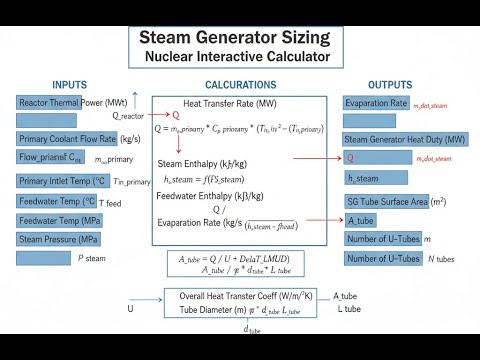
Steam Generator Sizing Calculator
How to Use This Calculator
This calculator is intended for education, concept evaluation, and preliminary design. Results are based on the equations and assumptions described on this page, but cannot account for every real-world load case, tolerance, material property, environmental condition, installation detail, safety factor, code, or regulatory requirement. Verify all inputs, assumptions, units, and results independently before selecting components or using the result in a real application. Safety-critical, structural, medical, lifting, transportation, or regulated applications must be reviewed by a qualified engineer.
- Set the calculator to whichever mode fits your problem—area, power, tube count, velocities, effectiveness, or pressure drop.
- Enter the numbers you actually have (temperatures, power, tube size, flow rates, etc.) in the fields provided.
- Check your units match (MW, °C, mm, m, etc.). The calculators don’t autoscale units.
- Hit Calculate to get the answer you’re after.
Nuclear Steam Generator Sizing Interactive Visualizer
Watch how thermal power, temperatures, and tube geometry drive the required heat transfer area in nuclear PWR steam generators. Adjust inputs to see real-time calculations of LMTD, effectiveness, and tube count for proper sizing.
HEAT TRANSFER AREA
3,817 m²
LMTD
27.3°C
TUBE COUNT
3,180
EFFECTIVENESS
0.67
FIRGELLI Automations — Interactive Engineering Calculators
Core Equations
Here are the main equations for heat transfer area calculations and related sizing.
Heat Transfer Area Calculation
A = Q / (U × LMTD)
A = required heat transfer area (m²)
Q = thermal power transfer (W)
U = overall heat transfer coefficient (W/m²·K)
LMTD = log mean temperature difference (K)
Use the formula below to calculate the log mean temperature difference.
Log Mean Temperature Difference
LMTD = (ΔT1 - ΔT2) / ln(ΔT1 / ΔT2)
ΔT1 = temperature difference at hot end = Tprimary,in - Tsecondary (K)
ΔT2 = temperature difference at cold end = Tprimary,out - Tsecondary (K)
Use the formula below to calculate the number of tubes required.
Number of Tubes Required
N = A / (π × Do × L)
N = number of tubes (dimensionless)
Do = tube outer diameter (m)
L = active tube length (m)
Use the formula below to calculate flow velocity.
Flow Velocity
v = ṁ / (ρ × Aflow)
v = flow velocity (m/s)
ṁ = mass flow rate (kg/s)
ρ = fluid density (kg/m³)
Aflow = flow cross-sectional area (m²)
Use the formula below to calculate heat exchanger effectiveness.
Heat Exchanger Effectiveness
ε = Qactual / Qmax = Cmin(Th,in - Th,out) / [Cmin(Th,in - Tc,in)]
ε = effectiveness (dimensionless, 0 to 1)
Qactual = actual heat transfer rate (W)
Qmax = maximum possible heat transfer rate (W)
Cmin = minimum heat capacity rate (W/K)
Use the formula below to calculate pressure drop through the tubes.
Pressure Drop (Darcy-Weisbach)
ΔP = f × (L / D) × (ρv² / 2)
ΔP = pressure drop (Pa)
f = Darcy friction factor (dimensionless)
L = tube length (m)
D = tube inner diameter (m)
ρ = fluid density (kg/m³)
v = flow velocity (m/s)
Simple Example
Suppose a steam generator must transfer 500 MW of thermal power. Primary coolant enters at 320°C and exits at 290°C; secondary steam sits at 275°C. The overall heat transfer coefficient U is 4,800 W/m²·K.
- Hot end ΔT: 320 − 275 = 45°C
- Cold end ΔT: 290 − 275 = 15°C
- LMTD: (45 − 15) / ln(45/15) = 30 / 1.099 = 27.3°C
- Required area: 500 × 10⁶ / (4,800 × 27.3) = 3,817 m²
Theory & Engineering Applications
Nuclear Steam Generator Fundamentals
PWR steam generators sit at the core of the nuclear heat removal chain. Unlike a fossil-fired boiler, you’ve got an indirect, closed cycle: all the heat leaves the core via pressurized primary water, and the only place it’s supposed to go is into the secondary feedwater through the tube bundle. The core aim is simple—keep the radioactive and non-radioactive sides separate while moving as much energy as possible. Everything stems from that.
Most PWR plants use a vertical U-tube steam generator (SG), roughly 20 meters tall and up to 5 meters wide, running 300–800 tonnes loaded. Tube count in a full-size unit is anywhere from about 3,000 to 16,000, with common tube ODs around 19 mm. Primary water comes in around 325°C, up to 15.5 MPa, goes through the tubes, and leaves about 30°C cooler. The secondary side is at much lower pressure so it boils—typically you want 270–285°C steam out, with saturation pressure about 6–8 MPa.
Heat Transfer Coefficient Considerations
The overall U value in a steam generator generally falls between 3,500 and 6,000 W/m²·K. This isn’t a theoretical range—most plant specs need to land between 4,500 and 5,200. Four things matter for U: primary-side convection, tube wall conduction, fouling (both sides), and the boiling transfer coefficient on the secondary. U will degrade over service life—fouling and tube plugging eat into your actual performance, so you have to size for worst case, not the day you install it. Plan on a 15–25% fouling penalty as a basic assumption; ignore that and you’re gambling with capacity you can’t get back later.
Feedwater chemistry matters more than most expect. Secondary-side fouling, especially in tube support plate crevices, is a big reason many plants had to replace their SGs ahead of schedule (often costing $400 million or more). Tube material drives both heat transfer and longevity. Original Inconel 600 had decent corrosion resistance but cracked under PWR conditions. Inconel 690 (thermally treated) or Alloy 800 Modified are much tougher and handle stress corrosion cracking better. Wall thickness typically lands between 1.07 and 1.27 mm; make it thinner and you lose strength, thicker and your transfer drops.
Thermal-Hydraulic Design Methodology
Start your calculations with Q = UA × LMTD—the standard energy balance—but don’t expect a single iteration to get you there. The actual system is messier: U changes with two-phase flow, local boiling, fouling, and real tube geometry. Classic log mean temperature difference assumes counterflow, but U-tube generators mix things up. You need a correction factor F (typically 0.92–0.97 for U-tubes); F < 1 means you have to build in extra tube area to get the power transferred.
The secondary side isn’t just boiling water. As you move up the tube bundle, you go from subcooled boiling at the bottom, to full nucleate boiling in the middle, to steam/water separation up top. Circulation ratio—the ratio of total secondary flow to steam actually produced—is usually 3–5. Only about a quarter or less of the water turns into steam per pass. The rest recirculates, which keeps tubes wetted and heat transfer up, but makes the separator design much more critical so steam quality stays high and you don’t erode turbine blades.
Structural and Mechanical Design Constraints
Tube bundles can use square or triangular pitches. Triangular pitch gets you more tubes per shell but worse access for NDE and plugging. Pitch-to-diameter ratios are usually between 1.25 and 1.4—closer tubes mean more transfer but raise vibration risk and are harder to manufacture. Tube support plate spacing is usually every 0.5–0.7 meters to keep tubes stable against flow-induced vibration, but these create spaces where corrosion can hide and build up during off-normal operation.
If you don’t get the vibration right, you’ll have problems. Primary water speeds are typically 3.5–5.5 m/s, secondary side often over 2 m/s, both enough for vortex shedding and potential fluidelastic instability. U-bends need anti-vibration bars because there are no support plates in that region. Miss the vibration analysis and you risk tube failures and forced shutdowns—historically not rare.
Worked Engineering Example: Steam Generator Area Calculation
Let’s walk through a practical case for a Westinghouse 4-loop PWR at 3,411 MW thermal. Each SG has to move 852.75 MWt. Design details:
- Primary inlet: 326.7°C, Primary outlet: 293.3°C
- Secondary (steam): 279.4°C at 6.89 MPa
- U = 4,650 W/m²·K (already includes 20% fouling allowance)
- Tubes: Inconel 690 TT, OD 19.05 mm, wall 1.09 mm
- Length: 12.8 m
Step 1: LMTD
Hot end ΔT: 326.7 – 279.4 = 47.3°C
Cold end ΔT: 293.3 – 279.4 = 13.9°C
LMTD: (47.3 – 13.9) / ln(47.3/13.9) = 33.4 / 1.224 = 27.3°C
Step 2: Required Area
Q = 852.75 MW × 10⁶ = 8.5275e8 W
Correction factor F = 0.95 (typical for U-tubes)
Effective ΔT = 0.95 × 27.3 = 25.9°C
Area = 8.5275e8 / (4,650 × 25.9) = 8.5275e8 / 120,435 = 7,082 m²
Step 3: Tube Count
Area per tube = π × 0.01905 × 12.8 = 0.766 m²
Tubes = 7,082 / 0.766 = 9,246
Round up to nearest buildable: 9,260 tubes
Step 4: Primary Side Flow
Mass flow = Q / (c_p × ΔT_primary)
c_p ≈ 5,640 J/kg·K
ṁ = 8.5275e8 / (5,640 × 33.4) = 4,527 kg/s
Tube ID = 19.05 – 2×1.09 = 16.87 mm = 0.01687 m
Area per tube = π × (0.01687²) / 4 = 2.235e-4 m²
Total area = 9,260 × 2.235e-4 = 2.070 m²
ρ ≈ 714 kg/m³
Velocity = 4,527 / (714 × 2.070) = 3.06 m/s (within typical operating range)
Step 5: Check Margin
Actual area: 9,260 × 0.766 = 7,093 m²
Margin: (7,093 – 7,082)/7,082 = 0.16%
That’s a lean but workable design; fouling is already covered in the chosen U value. Plugging tubes up to about 10% is standard, but reduces margin proportionally.
Industry Applications Across Nuclear Fleet
This sizing method is used on PWR SGs worldwide—whether you’re dealing with a Westinghouse, Framatome, Russian VVER (horizontal design but governed by similar equations), or even Canadian CANDU (much smaller and horizontal but basically the same logic). If you’re uprating power, replacing SGs, or need numbers for a licensing review, you’ll use these calculations. Regulators tie core departure from nucleate boiling (DNB) safety margins directly to your ability to remove heat—so your plant’s design basis always circles back to heat exchanger sizing and margins. Real-world risk cases—like tube ruptures—are modeled with these equations too. For more calculators, check the engineering calculator hub.
Practical Applications
Scenario: Replacement Steam Generator Design Evaluation
Jennifer is reviewing proposals for replacement steam generators at her plant. The old ones are heavily degraded—23% of the tubes are already plugged, and plant output is down 4%. The bids have different tube counts and materials. Jennifer plugs each vendor’s specs into the calculator: Vendor A, 7,240 m² with a 12% area margin for $40 million less; Vendor B, 7,890 m² with a 23% margin but $47 million higher. Based on calculated margins and required technical spec, she shows that Vendor A’s option is sufficient for 40 years with room for expected degradation and recommends it up the chain. The utility saves significantly, and there’s no practical performance gap.
Scenario: Power Uprate Thermal Analysis
Marcus is tasked to assess if the steam generators can still do their job after a 2% power uprate. He checks summer and winter cooling conditions, evaluates degraded performance with 8% tube plugging, and uses the calculator to verify area and velocity are still within limits. Result: the plant keeps at least 6.7% heat transfer margin, justifying the uprate for both plant owners and the regulator. That added power turns into a nice bump in annual revenue—without the risk of surprise heat transfer bottlenecks.
Scenario: Steam Generator Performance Monitoring and Diagnostics
Dr. Yuki Tanaka watches plant parameters and sees primary outlet temperature slowly drift up, even as reactor power holds steady. That means the steam generator isn’t pulling heat as efficiently. Inputting observed temps and geometry into the calculator in reverse, Dr. Tanaka gets a heat transfer coefficient lower than both the original design and expected fouled value—by about 10%. That’s a strong indicator of abnormal fouling or particular tube issues, prompting targeted inspection and chemical cleaning that brings performance back, avoiding premature tube plugging and millions in lost output.
Frequently Asked Questions
Why do PWR steam generators use U-tubes instead of straight-tube designs? +
How does fouling affect steam generator performance over its operating life? +
What is the significance of the log mean temperature difference in steam generator sizing? +
Why is tube pitch optimization important in steam generator design? +
How do operating conditions affect steam generator thermal performance? +
What role does steam generator sizing play in plant safety analysis? +
Free Engineering Calculators
Explore our complete library of free engineering and physics calculators.
Browse All Calculators →🔗 Explore More Free Engineering Calculators
About the Author
Robbie Dickson — Chief Engineer & Founder, FIRGELLI Automations
Robbie Dickson brings over two decades of engineering expertise to FIRGELLI Automations. With a distinguished career at Rolls-Royce, BMW, and Ford, he has deep expertise in mechanical systems, actuator technology, and precision engineering.
Video Walkthrough - How to Use This Calculator
Need to implement these calculations?
Explore the precision-engineered motion control solutions used by top engineers.


