Working out safe distances and required shielding for radioactive sources is an essential part of radiation work—it’s not optional. If you get it wrong, you risk serious health effects or regulatory trouble. This Radiation Exposure Distance Shielding Calculator lets you estimate dose rates at varying distances or through shielding using the inverse square law and exponential attenuation, based on your source activity inputs. You’ll find this approach used in nuclear medicine, industrial radiography, and planning for work in nuclear power facilities. On this page, you’ll also find the key equations, a worked example, some practical engineering theory, and an FAQ tackling the kinds of issues people actually face in the field.
What is radiation exposure distance shielding?
Radiation exposure distance shielding is simply about using a combination of distance and physical barriers to reduce the dose someone receives from a radioactive source. The basic rule: the farther you are, or the more material between you and the source, the less radiation you’ll get.
Simple Explanation
Think about how a bonfire feels: close up, you get hot fast. Step back to twice the distance—the heat isn’t just halved, it drops to a quarter. Radiation drops off in the same way as you move away. Throw a lead sheet between you and the source? Most of the radiation gets absorbed before it gets to you, similar to how a fireproof screen blocks out much of the heat.
📐 Browse all 1000+ Interactive Calculators
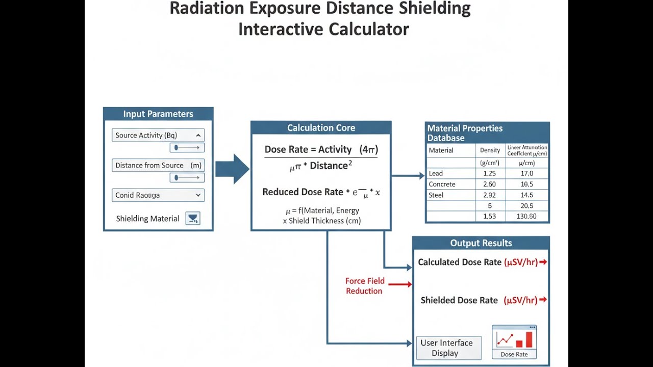
Radiation Shielding Diagram

Radiation Exposure Distance Shielding Calculator
How to Use This Calculator
This calculator is intended for education, concept evaluation, and preliminary design. Results are based on the equations and assumptions described on this page, but cannot account for every real-world load case, tolerance, material property, environmental condition, installation detail, safety factor, code, or regulatory requirement. Verify all inputs, assumptions, units, and results independently before selecting components or using the result in a real application. Safety-critical, structural, medical, lifting, transportation, or regulated applications must be reviewed by a qualified engineer.
- Pick your Calculation Mode—options include calculating dose at distance, a safe distance for a set dose, shielded dose, minimum shield thickness, maximum allowed exposure time, or the source activity for a given dose.
- Enter the relevant values for your chosen mode. You may need the original dose rate (mSv/h), distance (m), attenuation coefficient (cm⁻¹), or shield thickness (cm).
- If you want to see an example, use the Try Example button to auto-fill typical inputs.
- Click Calculate to get your result.
Radiation Exposure Distance Shielding Interactive Calculator
You can see for yourself how changing distance or shielding materials cuts dose rates, using the regular inverse square and exponential attenuation laws. Adjust source activity, move your position, or change shield thickness to see effects straight away—useful if you’re planning shielding or standoff for a job in the nuclear or radiography field.
DOSE RATE
4.8 mSv/h
REDUCTION
96.2%
SAFETY STATUS
MODERATE
FIRGELLI Automations — Interactive Engineering Calculators
Governing Equations
Use the formula below to calculate dose rate at a new distance using the inverse square law.
Inverse Square Law
D2 = D1 × (r1 / r2)2
Where:
- D1 = Initial dose rate at distance r1 (mSv/h)
- D2 = Dose rate at new distance r2 (mSv/h)
- r1 = Initial distance from source (m)
- r2 = New distance from source (m)
Use the formula below to calculate the transmitted dose rate through a shielding material.
Exponential Attenuation Law
D = D0 × e-μx
Where:
- D = Transmitted dose rate through shield (mSv/h)
- D0 = Incident dose rate before shielding (mSv/h)
- μ = Linear attenuation coefficient (cm-1)
- x = Shield thickness (cm)
Use the formula below to calculate half-value layer and tenth-value layer from the attenuation coefficient.
Half-Value Layer and Tenth-Value Layer
HVL = 0.693 / μ
TVL = 2.303 / μ
Where:
- HVL = Half-value layer thickness that reduces intensity by 50% (cm)
- TVL = Tenth-value layer thickness that reduces intensity by 90% (cm)
- μ = Linear attenuation coefficient (cm-1)
Use the formula below to calculate the required shield thickness to achieve a target dose rate.
Required Shield Thickness
x = ln(D0 / Dtarget) / μ
Where:
- x = Required shield thickness (cm)
- D0 = Unshielded dose rate (mSv/h)
- Dtarget = Desired dose rate after shielding (mSv/h)
- μ = Linear attenuation coefficient of shield material (cm-1)
Use the formula below to calculate maximum allowable exposure time from a dose rate and dose limit.
Maximum Exposure Time
t = Dlimit / Ḋ
Where:
- t = Maximum allowable exposure time (h)
- Dlimit = Regulatory dose limit (mSv)
- Ḋ = Dose rate at work location (mSv/h)
Simple Example
Scenario: A source produces 50 mSv/h at 1 m. What is the dose rate at 5 m?
- Initial dose rate (D1): 50 mSv/h
- Initial distance (r1): 1 m
- New distance (r2): 5 m
- D2 = 50 × (1/5)² = 50 × 0.04 = 2.0 mSv/h
Move away to five times the distance, and your dose drops to 1/25th—so from 50 mSv/h, you’re down to 2.0 mSv/h.
Theory & Engineering Applications
Fundamental Radiation Interaction Physics
If you’re dealing with a point source in open air or vacuum, radiation intensity drops off as the inverse square of distance—pure geometry. For point sources, the only major factor is how the radiation spreads out: at a distance r, the intensity is spread over the surface area of a sphere (4πr²). This only holds if you’re much further away than the source’s own dimensions; real sources aren’t perfect points, so for big sources or close-up work this breaks down.
As for what happens in shielding: the linear attenuation coefficient μ tells you how quickly the radiation gets eaten up inside a material, and it depends both on the shield’s atomic number and on the photon energy involved. At low energies, photoelectric absorption dominates. In the middle, Compton scattering is in control, and at high energies pair production starts to show up. If you need serious attenuation at moderate X-ray energies, lead’s a top pick—but it’s not as efficient at several MeV, where concrete or steel might suddenly be more practical if you don’t care about size or mass.
Build-Up Factor Corrections for Real-World Shielding
The straight exponential attenuation formula assumes only the direct beam gets through. In practice, scattered radiation—photons bouncing around in the shield—means you end up with more dose than this “ideal” calculation suggests. The “build-up factor” covers this extra contribution. If you’re working with broad beams or thick shielding, especially at higher energies, actual dose on the far side of your shield can be noticeably higher, sometimes double. For design, the typical method is to multiply the simple exponential result by a build-up factor (depends on shield, thickness, and photon energy). If you’re designing major hospital or industrial shielding, you’ll usually need to add this correction or add thickness for a conservative result. For complex source shapes or layouts, point kernel and Monte Carlo methods are the reliable ways to account for scatter and build-up, but these need real input data and computation time.
Distance Optimization in Radiation Work Planning
In most cases, simply increasing distance is the cheapest, quickest way to bring a dose down. If you double your distance from a point source, dose drops by a factor of four. Triple it, and you're at a ninth of the original value. This is why a lot of radiation work, especially in field radiography or nuclear power outage work, pushes operators to use remote tools, poles, or robotic gear where possible. Of course, in tight spaces—vaults, vessels, around piping—distance control isn’t always realistic, so you have to combine it with practical shielding and survey work. And don’t trust the theory alone: reflective or confined spaces, or poor collimation, may cause the actual dose rate to come out higher than the textbook says. Always check with a calibrated meter if possible.
Material-Specific Attenuation Properties
Lead gives good “bang for your buck” at low-to-mid photon energies, but if you’re shielding higher-energy sources, that advantage erodes. For thick walls or where cost and space matter, concrete is often the go-to, despite needing bigger thickness. For portable setups or high-Z needs in tight spaces, tungsten and even depleted uranium show up, but those come with cost and handling issues. Water and plastics handle neutrons reasonably well, sometimes better than heavy metals if that’s your main hazard. Don’t pick a shield based only on density—look at attenuation coefficients at your energy of interest, cost, mechanical properties, and if you’re in a work environment, consider handling and reuse.
Regulatory Dose Limits and Compliance Calculations
Most jurisdictions follow pretty similar occupational dose guidelines—20 mSv per year, averaged, and 1 mSv per year for the public, with some stricter limits for specific tissues. Any time you predict a dose rate over the allowed level, you’ll need barriers, warning signs, and possibly dose monitoring at those sites. For work planning, multiply your measured or calculated dose rate by the estimated time in the area (don’t forget breaks and inefficiencies). Add a margin—work usually runs longer or can be interrupted, and actual doses can come out higher than you expect from paper calculations.
Worked Example: Shielded Distance Calculation for Industrial Radiography
Problem Statement: An industrial radiography team uses a 3.7 TBq (100 Ci) iridium-192 source for weld inspection. The gamma constant for Ir-192 is 0.485 mSv·m²·GBq⁻¹·h⁻¹. They need to establish a controlled area boundary where the dose rate does not exceed 0.02 mSv/h (20 μSv/h). The source is positioned behind a 3 cm steel plate (μ = 0.462 cm⁻¹ for Ir-192's average 0.38 MeV gamma energy). Calculate: (a) the unshielded dose rate at 5 meters, (b) the shielded dose rate at 5 meters, and (c) the minimum distance required to achieve 0.02 mSv/h with the steel shielding in place.
Solution Part (a) - Unshielded Dose Rate:
The dose rate at distance r from a point source is given by:
Ḋ = Γ × A / r²
Where Γ = 0.485 mSv·m²·GBq⁻¹·h⁻¹, A = 3700 GBq (converting from 3.7 TBq), and r = 5 m.
Ḋ = (0.485 × 3700) / 5²
Ḋ = 1794.5 / 25
Ḋ = 71.78 mSv/h
This unshielded dose rate is extremely high—one year’s dose limit in less than 20 minutes. Proper shielding and sufficient distance are required.
Solution Part (b) - Shielded Dose Rate at 5 Meters:
Calculate the transmission factor through 3 cm steel:
T = e⁻ᵘˣ = e⁻⁽⁰·⁴⁶²⁾⁽³⁾
T = e⁻¹·³⁸⁶
T = 0.250
The steel blocks about 75% of the dose—leaving you with 25%, or:
Ḋshielded = 71.78 × 0.250 = 17.95 mSv/h
Still not low enough for unmonitored entry. The lead blanket reduces the dose, but you’re still well over area limits. The steel afforded 1.85 HVLs (HVL = 0.693/0.462 = 1.50 cm), meaning dose was dropped by a factor of 3.6 or so.
Solution Part (c) - Minimum Distance for 0.02 mSv/h Target:
You want to know how far out you need to go from the source plus steel to reach a safe dose:
Ḋtarget = (Γ × A × T) / r²
Rearrange for distance:
r = √[(Γ × A × T) / Ḋtarget]
r = √[(0.485 × 3700 × 0.250) / 0.02]
r = √[448.625 / 0.02]
r = √22,431.25
r = 149.8 meters
Your exclusion boundary moves out to nearly 150 meters with 3 cm of steel in place. Without the shield, you'd need just under 300 meters, so the steel lets you halve the controlled area radius. In a typical field job, add local shielding, collimators, and clear signage—real sites rarely permit such wide-open zones, so you need every tool for dose control. Real scatter and build-up effects could nudge this baseline calculation higher by 10–20% depending on situation, so always check with actual field measurements if you can. Similar calculations work for planning barricades and monitoring for radiography, hot cell shielding, or power plant jobs. For more tools, see the calculator library.
Practical Applications
Scenario: Hospital Radiation Safety Officer Designing PET-CT Suite Shielding
Dr. Jennifer Martinez, radiation safety officer at a regional cancer center, must design shielding for a new PET-CT facility housing a fluorine-18 FDG synthesis module and imaging suite. The cyclotron-produced F-18 arrives weekly at 370 GBq activity, decaying with a 110-minute half-life while stored in a hot cell before patient dose preparation. Using the calculator's shielded dose mode with lead's attenuation coefficient of 0.77 cm⁻¹ for 511 keV annihilation photons, she determines that 4.5 cm of lead brick (3 HVLs at 0.90 cm each) reduces the 92 mSv/h surface dose from the storage vial to 11.5 mSv/h—still requiring restricted access. Adding distance calculations, she establishes a 2.5-meter minimum approach boundary where technicians preparing doses would receive 1.84 mSv/h, allowing 10-minute maximum occupancy periods per regulatory limits. The combined shielding and distance strategy reduces technician doses by 98.7% compared to unshielded contact scenarios, enabling safe radiopharmacy operations while maintaining efficient patient scheduling for the 12-15 daily PET scans. Her calculations justify the $47,000 shielding installation cost by demonstrating ALARA compliance and eliminating the need for robotic dose dispensing equipment that would have cost $180,000.
Scenario: Pipeline Inspector Calculating Safe Standoff During Gamma Radiography
Marcus Chen, a certified industrial radiographer with 12 years' experience, inspects welds on a 36-inch natural gas transmission pipeline using a 2.96 TBq (80 Ci) iridium-192 source in a 660B exposure device. Working in a rural area at night to minimize public exposure, he uses the safe distance calculation mode to determine that his survey boundary must extend 127 meters to achieve the 0.02 mSv/h unrestricted area limit. His two-person crew establishes this perimeter using reflective barriers and warning lights, then positions the source using a 20-meter guide tube that allows him to maintain 25 meters minimum distance during the 4-minute exposures. At this distance, the calculator shows his dose rate drops to 1.82 mSv/h, and the maximum exposure time mode indicates he can safely perform 8 exposures (32 minutes total beam-on time) before reaching his company's conservative 50 mSv per job administrative limit—well below the 0.25 mSv he actually receives during the job. The calculations prove critical when a motorist approaches the barrier at 2 AM; Marcus immediately retrieves the source using the emergency crank, and his documented safe distance calculations demonstrate regulatory compliance during the subsequent incident investigation, avoiding the $75,000 citation issued to another company whose insufficient boundary allowed public exposure.
Scenario: Nuclear Power Plant ALARA Coordinator Planning Valve Maintenance
Sarah Kowalski, ALARA coordinator at a 1200 MWe pressurized water reactor, plans maintenance on a containment isolation valve with deposited cobalt-60 creating a 35 mSv/h contact dose rate on the valve body surface. The four-hour valve repacking job requires workers to maintain hand contact with the valve for torque wrench operations, making distance controls impractical. Using the required shielding thickness calculator mode with lead wool's attenuation coefficient of 1.23 cm⁻¹ for Co-60's 1.17-1.33 MeV gammas, she calculates that 3.8 cm of lead blanket shielding (6.7 HVLs) will reduce the dose to 0.28 mSv/h at the work surface. She then uses the exposure time calculator to determine that each technician can work 71 minutes before reaching the 0.2 mSv per-job administrative limit, requiring a six-person rotation to complete the task. Her detailed shielding plan, backed by calculator-verified dose projections, reduces the collective crew dose from a projected 140 person-mSv (unshielded scenario) to 1.2 person-mSv—a 99.1% reduction that saves the utility approximately $420,000 in avoided dose costs at their $3,000 per person-mSv internal accounting value, while the custom lead blankets cost only $8,500 to fabricate and will be reused for similar jobs throughout the outage.
Frequently Asked Questions
Why does the inverse square law only apply to point sources, and when does it break down in practical situations? +
How do I select the correct attenuation coefficient when dealing with polyenergetic sources or multiple shielding layers? +
What safety factors should I apply to calculated shielding requirements for regulatory compliance? +
How do I account for scattered radiation and skyshine when establishing radiation area boundaries outdoors? +
What are the practical differences between using lead versus tungsten for portable shielding applications? +
How do I calculate effective dose from dose rate measurements for compliance with annual exposure limits? +
Free Engineering Calculators
Explore our complete library of free engineering and physics calculators.
Browse All Calculators →🔗 Explore More Free Engineering Calculators
About the Author
Robbie Dickson — Chief Engineer & Founder, FIRGELLI Automations
Robbie Dickson brings over two decades of engineering expertise to FIRGELLI Automations. With a distinguished career at Rolls-Royce, BMW, and Ford, he has deep expertise in mechanical systems, actuator technology, and precision engineering.
Video Walkthrough - How to Use This Calculator
Need to implement these calculations?
Explore the precision-engineered motion control solutions used by top engineers.


