Wireless control of linear actuators transforms static projects into dynamic, user-friendly systems. Whether you're building an automated hatch, adjustable furniture, or a custom access panel, a 2-channel remote control provides the convenience of wireless operation with extend and retract functionality at the press of a button. However, proper wiring and configuration are essential to ensure reliable operation and prevent damage to your control system.
This comprehensive guide covers everything you need to know about setting up, configuring, and troubleshooting a 2-channel remote control system for linear actuators. We'll walk through the basics of wiring, explain how to switch between momentary and latching modes, show you how to program multiple remotes, and detail safe methods for controlling high-current actuators and multiple actuator setups. Whether you're a DIY enthusiast tackling your first motorized project or an engineer seeking reliable wireless control solutions, this tutorial provides the technical details you need for successful implementation.
Understanding Momentary vs. Latching Control Modes
The 2-channel remote control receiver comes factory-programmed in momentary mode, but understanding the difference between momentary and latching operation is crucial for selecting the right mode for your application.
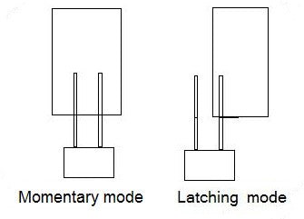
Momentary mode requires continuous button pressure to move the actuator. The actuator extends or retracts only while you hold the corresponding button on the remote. Release the button, and the actuator immediately stops. This mode provides precise control over actuator position and is ideal for applications where you need to stop at specific points along the stroke length, such as adjustable shelving, variable-height workstations, or any situation requiring fine positioning control.
Latching mode operates differently. A single button press starts the actuator moving, and it continues traveling the full stroke length until it reaches its internal limit switch—no continued button pressure required. Press the button again to reverse direction or stop movement. This mode is perfect for applications like automated doors, hatches, or TV lifts where you want full extension or retraction without holding the button continuously.
Switching Between Control Modes
Changing from momentary to latching mode (or vice versa) involves a simple jumper configuration on the receiver board:
- Open the receiver case to access the control board
- Locate the black jumper block on the front of the circuit board
- For momentary mode: Place the jumper across both pins (connecting them)
- For latching mode: Remove the jumper from both pins and place it on just one pin for storage
- Disconnect power from the receiver completely
- Reconnect power to reset the system and activate the new mode
The power cycle is essential—the receiver only reads the jumper configuration during startup. Simply moving the jumper without removing and reapplying power will not change the operating mode.
Basic Wiring Configuration
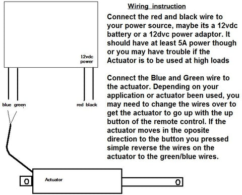
Proper wiring is fundamental to safe and reliable operation. The 2-channel receiver has clearly labeled terminals for straightforward connections:
- Power Input: Connect your 12V DC power supply positive lead to the positive terminal and negative lead to the negative/ground terminal on the receiver
- Actuator Connection: The two output channels connect directly to the actuator's motor leads. These connections determine extension and retraction direction
- Polarity: If the actuator moves in the wrong direction when you press a button, simply reverse the two motor wire connections at the receiver terminals
This basic configuration works perfectly for standard linear actuators drawing 5 amps or less, including our Premium and Classic series actuators. These actuators typically operate at 12V DC and draw between 2-5 amps depending on load and model specifications.
Programming Multiple Remote Controls
Many applications benefit from having multiple remotes—one mounted near the equipment, another for portable use, or several for different users. The 2-channel receiver can be programmed to recognize multiple remote transmitters simultaneously.
Step-by-Step Programming Process
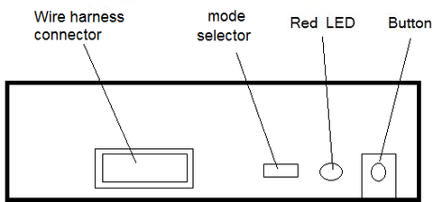
- Open the receiver case to access the circuit board
- Locate the programming button on the board (typically near the antenna connection)
- Press and hold the programming button for several seconds until the red LED begins flashing—this indicates the receiver is in learning mode
- Press any button on the first remote you want to program
- Repeat step 4 for each additional remote, pressing one button on each remote in sequence
- Disconnect power from the receiver
- Reconnect power to complete the programming sequence
Important: When programming multiple remotes, you must program all remotes during the same session, including any that were previously programmed. The learning process overwrites the previous remote memory. If you have four remotes and need to add a fifth, you'll need to reprogram all five remotes in sequence during that programming session.
Controlling High-Current Actuators with Relays
The 2-channel receiver board has a maximum current rating of 5 amps. While this accommodates most standard actuators, some high-force models exceed this limit. For example, our industrial actuators can draw up to 20 amps under load. Connecting a high-current actuator directly to the receiver will cause immediate and permanent damage to the control board.
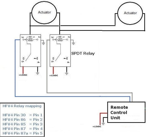
The solution is using SPDT (Single Pole Double Throw) relays rated for 20 amps or higher to isolate the receiver from the actuator. The receiver controls low-current relay coils, while the relay contacts handle the high actuator current. This configuration protects your control electronics while enabling wireless operation of powerful actuators.
Relay Wiring for High-Current Applications
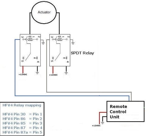
You'll need two 20-amp SPDT relays—one for each direction of travel (extend and retract). The wiring configuration creates an H-bridge circuit that reverses polarity to change actuator direction:
- Connect the receiver's channel outputs to the relay coils (low-current control signal)
- Wire the relay contacts to reverse the actuator's power connections based on which relay is energized
- Connect the main power supply through the relay contacts to the actuator
This relay-based approach is essential for any actuator exceeding 5 amps continuous draw. It's also the foundation for safely controlling multiple actuators simultaneously, as we'll discuss in the next section.
Wiring Multiple Linear Actuators
Many projects require synchronized movement of two or more linear actuators—applications like dual-lift mechanisms, coordinated hatches, or adjustable platforms. However, connecting multiple actuators directly to the receiver board creates two significant problems:
Current overload: Even if each actuator draws only 3 amps, two actuators create a 6-amp load, exceeding the receiver's 5-amp limit. Three or four actuators multiply this problem, risking immediate board failure.
Solution: Use relays to isolate the receiver from the actuators, exactly as described in the high-current section above. The relay configuration handles multiple actuators just as effectively as it handles single high-current units.
Power Supply Considerations
When operating multiple actuators, your power supply must provide sufficient current for all actuators running simultaneously. Calculate total current draw by adding the maximum current rating of each actuator. For example:
- Two Premium actuators at 5 amps each = 10-amp power supply minimum
- Three Classic actuators at 3 amps each = 9-amp power supply minimum
- Add 20% safety margin for optimal performance and longevity
Synchronization Considerations
It's important to understand that actuators controlled by the same remote signal will move together but not necessarily at exactly the same speed. Manufacturing tolerances, load differences, and internal friction create slight speed variations between actuators. The differences are typically small—often just a few millimeters over a full stroke—but they become more noticeable over repeated cycles.
For applications requiring precise synchronization, such as standing desks or lifting platforms, consider using feedback actuators with position sensors and a controller that can actively synchronize movement based on real-time position data. For more information on this topic, refer to our detailed tutorial on synchronous control of linear actuators.
Controlling Multiple High-Current Actuators
When your project involves multiple high-current actuators—for instance, two Heavy Duty Industrial Actuators each rated at 20 amps—standard 20-amp relays become inadequate. Two 20-amp actuators create a 40-amp total load, which would destroy 20-amp rated relay contacts.
The solution requires either higher-rated relays (40+ amps) or a modified wiring configuration where each actuator has its own dedicated relay pair. This second approach is often more practical and cost-effective:
- Use four 20-amp SPDT relays total (two pairs, one pair per actuator)
- Wire each relay pair to control one actuator independently
- Connect all relay coils in parallel to the receiver's control outputs so they operate simultaneously
- Use appropriately sized power supplies—either one 40+ amp supply or two 20-amp supplies (one per actuator)
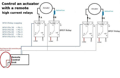
This configuration keeps current within each relay's rated limits while allowing simultaneous control of multiple heavy-duty actuators. Always verify that your total system current doesn't exceed your power supply capacity, and ensure adequate wire gauge for the current levels involved—undersized wiring creates voltage drop, heat, and potential fire hazards.
Safety and Troubleshooting Tips
Proper installation ensures reliable operation and prevents component damage. Keep these guidelines in mind:
- Never exceed current ratings: Always use relays when actuator current exceeds 5 amps or when controlling multiple actuators
- Check polarity: Reversed power supply connections can damage the receiver—verify positive and negative before applying power
- Secure all connections: Loose wire connections cause intermittent operation and create arcing that damages terminals
- Mount the receiver away from metal: Metal surfaces can interfere with RF reception, reducing remote range
- Use appropriate wire gauge: Undersized wire creates voltage drop and heat—use 18 AWG minimum for 5-amp circuits, 14 AWG for 20-amp circuits
- Test before final installation: Verify all functions work correctly before closing enclosures or completing permanent mounting
If your system isn't working as expected, systematically check these common issues:
- Receiver not responding: Verify power supply output voltage and connections
- Actuator moves in wrong direction: Reverse the two motor wire connections at the receiver or relay
- Remote range is poor: Reposition receiver away from metal surfaces or extend the antenna wire
- Actuator doesn't move: Check that current draw doesn't exceed board rating; verify all relay connections if using relays
- Mode won't change: Ensure power was completely disconnected and reconnected after moving the jumper
Selecting the Right Actuator for Remote Control
The 2-channel remote control works with virtually any DC linear actuator, but selecting the appropriate actuator for your application ensures optimal performance. Consider these factors:
Force requirements: Calculate the actual force needed to move your load, then select an actuator with 20-30% excess capacity for reliability and longevity. Our Premium series actuators range from 150 to 1,500 pounds of force, while industrial actuators provide up to 2,200 pounds.
Stroke length: Measure the total distance your application requires. Actuators are available in stroke lengths from 2 inches to 40+ inches. Remember that actuator body length equals approximately stroke length plus 8-12 inches depending on model, which affects mounting space requirements.
Speed requirements: Standard actuators move at speeds ranging from 0.5 to 2+ inches per second. Faster speeds generally provide less force. Consider whether your application prioritizes speed or force.
Duty cycle: Intermittent use applications (less than 20% duty cycle) can use standard actuators. Continuous or heavy-duty applications benefit from industrial actuators designed for extended operation.
Environmental conditions: Indoor applications work well with standard IP54-rated actuators. Outdoor installations or harsh environments require IP65 or IP66 rated units with enhanced sealing and corrosion resistance.
Frequently Asked Questions
What is the maximum range of the 2-channel remote control?
The 2-channel remote typically provides reliable operation at distances up to 30-50 feet in open air. Actual range depends on several factors including obstacles, metal structures that block RF signals, and electrical interference from other devices. For optimal range, mount the receiver with its antenna extended away from metal surfaces, and avoid enclosing it in metal boxes without providing an external antenna connection. If you need extended range, position the receiver as close to the typical operating location as possible.
Can I use this 2-channel remote control with 24V actuators?
The standard 2-channel receiver is designed for 12V DC operation and should not be used with 24V systems without verification of voltage compatibility. Using 24V with a 12V-rated receiver will damage the electronics. If you need wireless control for 24V actuators, contact FIRGELLI Automations to discuss 24V-compatible remote options or use 24V-rated relays with the 12V receiver controlling the relay coils while 24V power runs through the relay contacts to the actuators.
How many actuators can I control with one 2-channel remote?
You can control as many actuators as needed with one 2-channel remote, provided you use appropriate relays and power supplies. The receiver itself is limited to 5 amps, but by using relays rated for the required current and a sufficiently powerful supply, you can operate four, six, or even more actuators simultaneously. Each group of actuators will move together when the corresponding button is pressed. The practical limit is determined by your power supply capacity and the current rating of your relay system, not the remote control itself.
Why don't my multiple actuators move at exactly the same speed?
Even when connected to the same power source and control signal, individual actuators exhibit slight speed variations due to manufacturing tolerances, internal friction differences, and varying loads. These differences are typically minor—usually less than 5% speed variation—but they accumulate over repeated cycles. If precise synchronization is critical for your application, consider using feedback actuators that provide position sensing, combined with a controller that can actively synchronize movement based on real-time position data from each actuator.
What happens if I connect an actuator that draws more than 5 amps directly to the receiver?
Connecting a high-current actuator directly to the 5-amp rated receiver will cause permanent damage to the control board. The damage typically occurs immediately or within the first few operations. The receiver's circuit traces and switching components cannot handle currents above their design limit. This damage is not covered by warranty as it results from improper application. Always use appropriately rated relays when working with actuators that exceed the receiver's 5-amp capacity—this includes most industrial actuators and any multi-actuator setup.
Can I control two actuators separately with different buttons?
The 2-channel remote provides two channels that typically control forward and reverse for a single actuator (or group of actuators moving together). If you need independent control of two separate actuators or actuator groups, you should use a 4-channel remote control system. This provides separate extend/retract control for two independent actuators or actuator groups. The 4-channel system uses the same basic wiring principles but offers four output channels instead of two, enabling more complex control scenarios.
Do I need special mounting brackets for remote-controlled actuators?
Remote-controlled actuators use the same mounting brackets as any linear actuator—the control method doesn't affect mounting requirements. Select mounting brackets based on your actuator's mounting hole pattern and your application's structural requirements. Most actuators use clevis-style brackets that allow pivoting movement at both ends, which is essential for proper operation as the mounting points move relative to each other during extension and retraction.


