In practice, designing a filter, power stage, or RF circuit often means you need a specific inductance value, and connecting inductors in series is one of the most straightforward ways to get there. The Series Inductors Calculator here provides totals for series inductance, accounts for mutual coupling, and computes basics like energy storage and reactance—details you’ll need if you care about precise filter performance, power supply ripple, or RF matching. Even a small shift in inductance can move your filter's frequency or mess with rolloff. The examples and explanations below get into mutual coupling, what actually happens in real builds, and includes calculations you don’t want to skip.
What is series inductance?
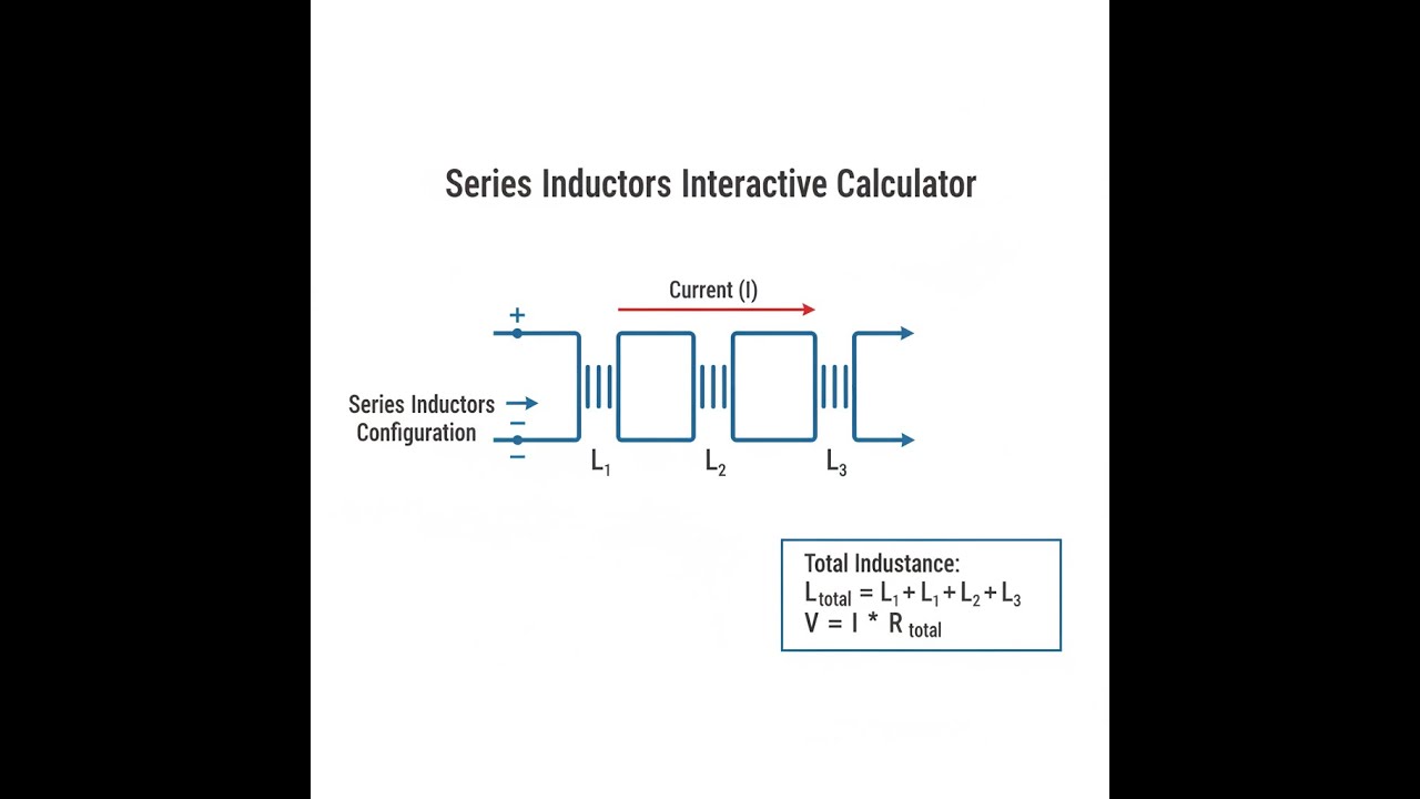
When you connect inductors end-to-end, you get a total inductance equal to the sum of their individual values—as long as their magnetic fields aren't interacting.
Simple Explanation
Series inductors are a lot like connecting pipes in a row: the same current goes through each, so their opposition to changing current adds together. But if you put them close enough for their magnetic fields to overlap, things change. Their fields can add (boosting overall inductance) or oppose (reducing it), so the result won’t just be the values summed up.
📐 Browse all 1000+ Interactive Calculators
Series Inductors Circuit Diagram

Series Inductors Calculator
How to Use This Calculator
This calculator is intended for education, concept evaluation, and preliminary design. Results are based on the equations and assumptions described on this page, but cannot account for every real-world load case, tolerance, material property, environmental condition, installation detail, safety factor, code, or regulatory requirement. Verify all inputs, assumptions, units, and results independently before selecting components or using the result in a real application. Safety-critical, structural, medical, lifting, transportation, or regulated applications must be reviewed by a qualified engineer.
- Select your calculation mode from the dropdown — total inductance, mutual inductance, required inductance, parallel equivalent, energy storage, or series reactance.
- Enter the number of inductors (for total mode) or the specific inductance, mutual inductance, current, or frequency values required by the selected mode.
- For the two-inductor mutual mode, also select whether the flux is aiding or opposing.
- Click Calculate to see your result.
Series Inductors Interactive Calculator
Visualize how multiple inductors combine in series to achieve target inductance values. Watch magnetic field interactions and see how mutual coupling affects total inductance in real-time.
TOTAL INDUCTANCE
100 mH
STORED ENERGY
0.20 J
REACTANCE @ 1kHz
628 Ω
FIRGELLI Automations — Interactive Engineering Calculators
Governing Equations
The key formulas for total series inductance are listed below.
Series Inductance (Without Mutual Coupling)
Ltotal = L1 + L2 + L3 + ... + Ln
Two Inductors with Mutual Inductance
Ltotal = L1 + L2 ± 2M
+ when flux is aiding, − when flux is opposing
Coupling Coefficient
k = M / √(L1L2)
where 0 ≤ k ≤ 1
Energy Storage
E = ½ L I²
Inductive Reactance
XL = ωL = 2πfL
Variable Definitions:
- Ltotal: Total series inductance (H, henries)
- L1, L2, Ln: Individual inductances (H)
- M: Mutual inductance between coils (H)
- k: Coupling coefficient (dimensionless, 0 to 1)
- E: Stored magnetic energy (J, joules)
- I: Current through inductors (A, amperes)
- XL: Inductive reactance (Ω, ohms)
- f: Frequency (Hz, hertz)
- ω: Angular frequency (rad/s)
Simple Example
With 3 inductors in series and no coupling: L1 = 10 mH, L2 = 20 mH, L3 = 30 mH.
Ltotal = 10 + 20 + 30 = 60 mH.
At 1 kHz, inductive reactance XL = 2π × 1000 × 0.060 = 376.99 Ω.
Theory & Practical Applications
Fundamental Principles of Series Inductance
Wire up inductors in series—if there’s no magnetic coupling—just add up all their henries for the total. The current flowing through each is the same, and voltage drop across the series chain adds up (following Kirchhoff's law). The math comes straight from V = L(dI/dt); put those in a row and you get total voltage as (sum of Ls) times dI/dt. But in an actual assembly, magnetic fields often interact, especially if inductors are close together. Now, mutual inductance M comes into play. The link can be positive (aiding, fields help each other), or negative (opposing, fields fight each other). If the coils are aiding, total inductance is L1 + L2 + 2M. If opposing, it’s L1 + L2 − 2M. Designers use this intentionally in transformers, and sometimes get caught by accident with coupled fields in filters or power circuits.
Mutual Inductance and Coupling Coefficient
The coupling coefficient (k) basically measures how strongly two inductors are magnetically linked, on a scale from zero (no link) to one (perfect). For two coils, mutual inductance tops out at √(L1L2). In the real world, air-core coils might have k values in the 0.1–0.5 range; ferrite transformers often hit 0.95 or above. In filter or RF work, even k values as low as 0.05–0.1 will noticeably affect performance—resonant frequencies shift, rolloff isn’t what you calculated. When coils are stacked or not spaced well on a PCB (especially vertically on multi-layer stacks), even small couplings add up. For instance, a 1 nH mutual inductance at 2.4 GHz is about 15 Ω—enough to detune sensitive circuits. Dot convention shows polarity: dots on the same side means fields add, opposite dots means fields subtract. This is critical in coupled inductor and transformer circuits, for instance when designing multiphase buck converters or EMI chokes. Get it wrong and instead of reducing ripple or noise, you can make it much worse.
Energy Storage and Current Distribution
Series-connected inductors all carry the same current, so the total energy stored is E = ½LtotalI². Unlike parallel inductors (which split the load), a single current surge loads all series inductors equally. If any one saturates or fails, the path for current is broken or limited by that weak link. In big DC-DC applications (think 50 A or more), splitting a required total inductance across multiple smaller units can make thermal management easier, but keep an eye on their saturation current—one weak inductor governs the whole string. If each has a 60 A saturation spec and your application draws 50 A, you’re running close to the edge. A modest overload pushes all into saturation. The voltage spike (inductive kick) when switching off grows with total L and dI/dt, so stacking inductors can mean higher stress on switches and MOSFETs. Doubling inductance doubles your voltage spike—so you may have to upsize your transistor voltage rating. In power supply work, there’s always a trade-off between reducing ripple (add more L) and limiting voltage surge (add less L).
Frequency-Dependent Behavior and Parasitic Effects
Once you get into high frequencies, the textbook model doesn’t cut it. Every real inductor has stray capacitance between its windings. At some frequency—its self-resonant frequency (SRF)—the inductive and capacitive reactances are equal, and it behaves like a parallel LC. Above this, the inductor won't filter or store energy effectively. When combining inductors in series, the total SRF generally drops compared to the individual SRFs, since inductance increases but capacitance (while it divides in series) rarely drops enough to maintain the same SRF. For instance, three 10 μH inductors in series (for 30 μH total) often end up with SRF 10–15% lower than a single 30 μH inductor, due to extra wiring and layout capacitance. RF circuits above 100 MHz usually stick to multilayer chip inductors to avoid SRF problems—wirewounds are too lossy and their SRF is too low.
Industrial Applications Across Sectors
In audio crossovers, series inductors cut out low frequencies to protect tweeters. For a 2-way crossover, a 0.6 mH series inductor will set a typical high-pass slope at about 3.2 kHz. Low DCR is important (less than 0.5 Ω) to maintain speaker performance, and at loud volumes these inductors see high current swings, so avoid cores that can't handle the peak flux. In power distribution, series inductors (called reactors) limit short-circuit current. For a 500 kVA transformer, a 50 μH reactor can hold fault current to a manageable level for fuses and circuit breakers. Go too high and you’ll lose too much voltage under load; too low and your protection gear may not trip fast enough. Multiphase buck converters (common in automotive ECUs) use series inductors to smooth ripple. By phasing multiple stages and sharing inductors, you reduce the needed output capacitance. Three 330 nH inductors at different phases can provide more ripple reduction than a single 1 μH unit—if current sharing and phasing are correct. For more calculators, check out the engineering calculator hub.
Worked Example: Multi-Stage LC Filter Design
Say you need a three-stage low-pass filter for a 24V, 10A power supply running at 150 kHz, with 60 dB EMI attenuation and less than 2% output ripple. You’ve picked 220 μF output capacitance (three 68 μF caps in parallel). Now, you’ll want to estimate the right series inductance and make sure your parts won’t saturate. Step 1: Calculate Required Cutoff Frequency
For 60 dB attenuation at 150 kHz and a second-order filter, the cutoff should be a decade below: fc = 150 kHz / 10 = 15 kHz. Using fc = 1/(2π√(LC)), solve for L: L = 1 / [(2π × 15,000)² × 220 × 10⁻⁶] ≈ 512 nH
Step 2: Distribute Inductance Across Three Stages
In a three-stage Butterworth filter, ratio the Ls as 1:2:1 for optimal damping. Total needed: 512 nH—so L1 = 128 nH, L2 = 256 nH, L3 = 128 nH. This gives you a steep rolloff without peaking near cutoff.
Step 3: Verify Saturation Current Requirements
Each inductor needs to handle 10A plus ripple current. The ripple calculated from ΔI = (Vin × D × (1−D)) / (L × fsw) quickly shows that small L values give huge current ripple at high frequency, often not realistic. Re-calculate for actual converter operation and layout; otherwise, your amps may exceed the rating by an order of magnitude. For output-stage ripple: the 220 μF cap at 150 kHz has XC ≈ 4.82 mΩ. If you want 2% ripple on 24V (0.48V), you’re looking at ripple current up to about 100A peak-to-peak. In practice, actual filtered ripple will be much lower, but always double check for margin.
Step 4: Select Physical Components and Calculate Series Inductance
You might pick two 150 nH parts (rated 18A) and a 300 nH part (rated 12A). Total is 600 nH (a little higher than calculated; your cutoff drops a bit, improving attenuation). But you're now limited by the lowest saturation value—in this case, 12A. Always make saturation current the basis for selection, not just L value.
Step 5: Evaluate Voltage Drop and Efficiency Impact
Check total series DC resistance (DCR): 1.8 mΩ + 2.5 mΩ + 1.8 mΩ = 6.1 mΩ. For 10A, that’s 0.061V drop, or 0.25% of your supply. Dissipated heat: 0.61W—likely acceptable, but always run the numbers for efficiency.
Frequently Asked Questions
▼ Why doesn't the series inductance formula work for all real-world circuits?
▼ How do I determine if series inductors are aiding or opposing?
▼ What happens if one inductor in a series chain saturates?
▼ Can I mix different inductor types and values in series?
▼ How does series inductance affect power supply start-up time?
▼ What measurement errors occur when testing series inductors with an LCR meter?
Free Engineering Calculators
Explore our complete library of free engineering and physics calculators.
Browse All Calculators →🔗 Explore More Free Engineering Calculators
- I2C Pull-Up Resistor Calculator
- LED Resistor Calculator — Current Limiting
- Capacitor Charge Discharge Calculator — RC Circuit
- I2C/SPI Bus Speed & Pull-up Resistor Sizing
- Skin Depth Calculator
- Capacitors In Series Calculator
- Rc Circuit Calculator
- Wire Gauge Calculator — Voltage Drop AWG
- Ohm's Law Calculator — V I R P
- Transformer Turns Ratio Calculator
About the Author
Robbie Dickson — Chief Engineer & Founder, FIRGELLI Automations
Robbie Dickson brings over two decades of engineering expertise to FIRGELLI Automations. With a distinguished career at Rolls-Royce, BMW, and Ford, he has deep expertise in mechanical systems, actuator technology, and precision engineering.
Video Walkthrough - How to Use This Calculator
Need to implement these calculations?
Explore the precision-engineered motion control solutions used by top engineers.


