If you’re designing a robotic arm with three joints, you need to know exactly where the tip is, and guessing won’t get you far. With three links and three joints, manual calculations get messy fast. This 3-Link Planar Forward Kinematics Calculator gives you the end effector’s X,Y coordinates from your chosen link lengths and joint angles. This is the sort of calculation you’ll rely on for workspaces that need accurate, repeatable movement—think automation, robotic assembly, or surgical arms. You’ll find FK equations, a worked example, practical notes, and a FAQ below.
What is 3-Link Planar Forward Kinematics?
Forward kinematics is about taking what you know—each link length and joint angle—and working out where the tip of your robot actually ends up. For a 3-link planar robot, all joints move in a flat plane, and you’re tracking down that tip using each link and angle as building blocks.
Simple Explanation
Picture your own arm: upper arm, forearm, hand—three links. If you know the shoulder, elbow, and wrist angles, you can work out exactly where your fingertip sits. That’s forward kinematics: turning joint angles into a tip position with a bit of trigonometry.
📐 Browse all 384 free engineering calculators
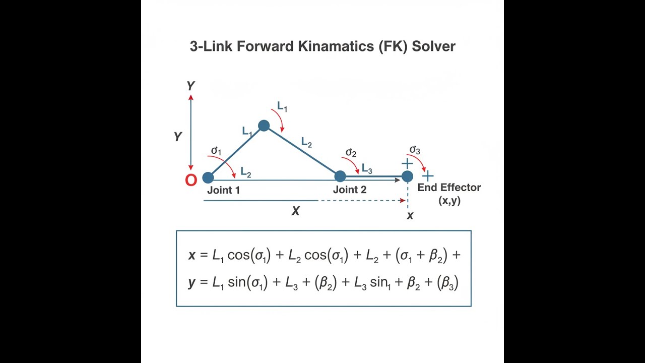
3-Link Planar Arm System Diagram

3-Link Forward Kinematics Calculator
3-Link Planar Forward Kinematics Interactive Visualizer
See how changing each joint and link updates the end effector position. Tweak values to watch the arm work through forward kinematics on the fly.
END EFFECTOR X
165 mm
END EFFECTOR Y
128 mm
REACH DISTANCE
209 mm
FIRGELLI Automations — Interactive Engineering Calculators
How to Use This Calculator
- Put in the three link lengths (L₁, L₂, L₃). Units don’t matter as long as you’re consistent.
- Enter each joint angle (θ₁, θ₂, θ₃) in degrees. θ₁ is from the X-axis; θ₂ and θ₃ are relative to the previous links.
- Double-check all six values: positive, consistent lengths, and angles that make sense for your setup.
- Hit Calculate to get the tip coordinates.
This calculator is intended for education, concept evaluation, and preliminary design. Results are based on the equations and assumptions described on this page, but cannot account for every real-world load case, tolerance, material property, environmental condition, installation detail, safety factor, code, or regulatory requirement. Verify all inputs, assumptions, units, and results independently before selecting components or using the result in a real application. Safety-critical, structural, medical, lifting, transportation, or regulated applications must be reviewed by a qualified engineer.
Mathematical Equations
3-Link Planar Forward Kinematics
Here’s how you get the end effector position for a 3-link planar arm.
The FK equations for this setup stack each joint’s effect using simple trig and vector addition:
Cumulative Joint Angles:
α₁ = θ₁
α₂ = θ₁ + θ₂
α₃ = θ₁ + θ₂ + θ₃
End Effector Position:
x = L₁ cos(α₁) + L₂ cos(α₂) + L₃ cos(α₃)
y = L₁ sin(α₁) + L₂ sin(α₂) + L₃ sin(α₃)
Reach Distance:
r = √(x² + y²)
Where:
- L₁, L₂, L₃ = Link lengths
- θ₁, θ₂, θ₃ = Joint angles (degrees)
- α₁, α₂, α₃ = Cumulative angles from base frame
- (x, y) = End effector Cartesian coordinates
- r = Distance from origin to end effector
Simple Example
Example: L₁ = 100 mm at θ₁ = 0°, L₂ = 100 mm at θ₂ = 0°, L₃ = 100 mm at θ₃ = 0°
Cumulative angles: α₁ = 0°, α₂ = 0°, α₃ = 0°
x = 100×cos(0°) + 100×cos(0°) + 100×cos(0°) = 300 mm
y = 100×sin(0°) + 100×sin(0°) + 100×sin(0°) = 0 mm
Result: End effector at (300, 0) mm, so the arm is fully stretched along the X-axis.
Technical Guide & Applications
Understanding 3-Link Forward Kinematics
Adding a third joint to a planar arm changes how you design and program motion. It extends the reach and lets you work around more obstacles, but you’ll notice it also makes the math a bit more involved. Tracing the effect of every angle and link is essential for any system where position accuracy and path matter—whether you’re welding, assembling, or automating pick-and-place jobs.
Forward kinematics is direct calculation: you know the link lengths and joint angles, and you want to find out where the tip is. Every joint’s rotation shifts everything beyond it. The math boils down to adding up the contributions of each joint, using trig for each link along the chain.
Engineering Principles
The underlying math can be written out with transformation matrices or Denavit-Hartenberg parameters. But for a planar system, you’re almost always just adding up the angles and plugging into basic trig. Every downstream link depends on its own joint and all upstream joints. That’s why you always build up the cumulative angle for each link when you calculate tip position.
The practical upshot: moving any joint will shift all links that come after it. That’s what gives you both the flexibility—and the complexity—of multi-link arms. Cumulative angles are just a practical shorthand to keep the calculations organized.
Practical Applications
Industrial Robotics: Three-link arms are common anywhere you need more dexterity than a basic SCARA robot. The third joint helps with picking parts in tight layouts or welding from awkward directions.
Medical Devices: Some robotic surgical systems and rehab machines use three-link layouts to follow complex jointed trajectories that match biological motion.
Automation Systems: In packaging or sorting, three-link arms help reach further or around more obstacles, and pairing with linear actuators lets you add in translation if you need it.
Worked Example
Say you’ve got:
- Link 1 (L₁): 150 mm, Joint angle (θ₁): 45°
- Link 2 (L₂): 120 mm, Joint angle (θ₂): 30°
- Link 3 (L₃): 80 mm, Joint angle (θ₃): -15°
Step 1: Add up angles
- α₁ = 45° = 0.785 rad
- α₂ = 45° + 30° = 75° = 1.309 rad
- α₃ = 45° + 30° + (-15°) = 60° = 1.047 rad
Step 2: Plug in the FK equations
- x = 150×cos(45°) + 120×cos(75°) + 80×cos(60°)
- x = 150×0.707 + 120×0.259 + 80×0.500
- x = 106.1 + 31.1 + 40.0 = 177.2 mm
- y = 150×sin(45°) + 120×sin(75°) + 80×sin(60°)
- y = 150×0.707 + 120×0.966 + 80×0.866
- y = 106.1 + 115.9 + 69.3 = 291.3 mm
Result: Tip is at (177.2, 291.3) mm from base, reach is 340.4 mm.
Design Considerations
Workspace Analysis: With three links, the workspace isn’t just wider—it’s more complicated. You can reach the same spot with different joint angles sometimes, and that’s handy for dodging obstacles or avoiding overextending a joint.
Singularity Management: When the arm goes straight, you hit a singularity—the system can lose a degree of freedom, and some moves become impossible. Use the calculator with extreme angles to spot these cases before building or programming. Try not to run the robot at full stretch in your regular paths if you can help it.
Actuator Selection: The torque at each joint depends on what comes after, so don’t size motors or actuators in isolation. If you need both rotary and linear motion, linear actuators can be stacked in as needed.
Advanced Considerations
Dynamic Effects: Forward kinematics handles pure position. But in the real world, inertia and acceleration matter, especially if you’re moving at any speed. Position models alone won’t tell you how much the arm will flex or jiggle under load—you’ll need more calculations for that.
Joint Limits: Every joint has a usable range. The FK equations work for any angle but in practice you can only reach configurations that stay inside joint limits. If you overshoot those, mechanical stops or software should prevent damage.
Calibration: Even small errors in link length or zero position cause drift at the tip. Periodic calibration is basic maintenance if you want reliable accuracy over time.
Integration with Control Systems
Forward kinematics normally runs as part of the core robot software, often in the main feedback loop. It’s fast and light enough for embedded controllers. Before you ever build, plug your numbers into the calculator to check you’ll have enough reach, or to get a ballpark idea of joint angles needed for real tasks. If you’re combining with slides or extra axes, confirm your workspace covers what you actually need without interference.
Frequently Asked Questions
What is the difference between forward and inverse kinematics? ▼
How do I determine the workspace of a 3-link robot arm? ▼
What units should I use for link lengths and angles? —
How does joint coupling affect the motion in 3-link systems? ▼
Can this calculator be used for 3D robotic arms? ▼
What are kinematic singularities and how do I avoid them? ▼
📐 Explore our full library of 384 free engineering calculators →
About the Author
Robbie Dickson
Chief Engineer & Founder, FIRGELLI Automations
Robbie Dickson brings over two decades of engineering expertise to FIRGELLI Automations. With a distinguished career at Rolls-Royce, BMW, and Ford, he has deep expertise in mechanical systems, actuator technology, and precision engineering.
Need to implement these calculations?
Explore the precision-engineered motion control solutions used by top engineers.


