Modeling a diode's current-voltage behavior precisely is the difference between a circuit that works on paper and one that performs across real temperature ranges and operating conditions. Use this Shockley Diode Calculator to calculate diode current, forward voltage, saturation current, temperature, or ideality factor using voltage, current, temperature, and material parameters as inputs. It's essential for rectifier design, photovoltaic cell modeling, RF detector circuits, and voltage regulator development. This page includes the full Shockley equation, a worked temperature compensation example, operating regime analysis, and a detailed FAQ.
What is the Shockley Diode Equation?
The Shockley diode equation describes how much current flows through a diode at a given voltage and temperature. It captures the exponential relationship between voltage and current that makes diodes behave so differently from resistors.
Simple Explanation
Think of a diode like a one-way valve that gets easier to open the harder you push — but the "easier to open" part is exponential, not linear. A small increase in voltage causes a large jump in current. Temperature matters too: a hotter diode lets current through more easily at the same voltage, which is why thermal management is never optional in power circuits.
📐 Browse all 1000+ Interactive Calculators
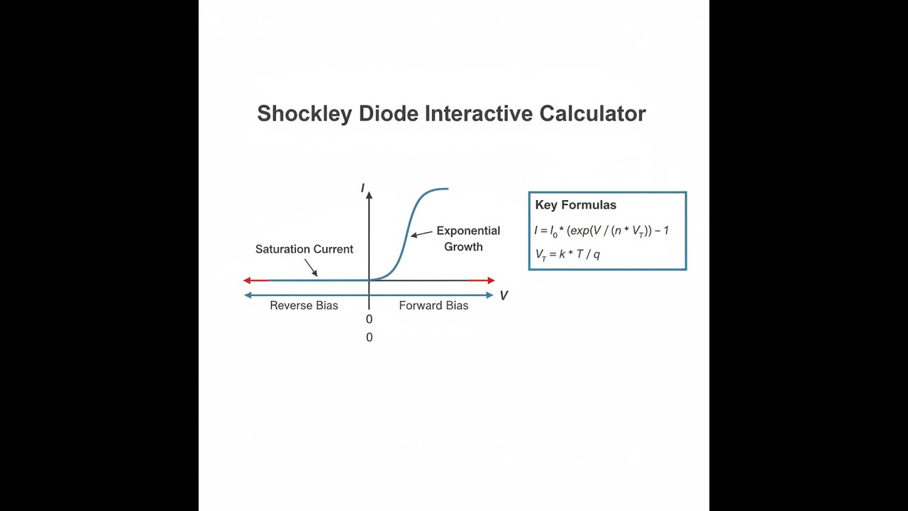
Diode I-V Characteristic Diagram

Interactive Shockley Diode Calculator
How to Use This Calculator
- Select your calculation mode from the dropdown — choose whether you want to solve for current, voltage, saturation current, temperature, or ideality factor.
- Enter the known values into the visible input fields: diode voltage (VD), saturation current (IS), ideality factor (n), and temperature (T) as required by your selected mode.
- If your mode requires diode current as an input, enter that value in the Diode Current field.
- Click Calculate to see your result.
Shockley Diode interactive visualizer
Explore the exponential current-voltage relationship in semiconductor diodes across different temperatures and bias conditions. Visualize how small voltage changes create dramatic current variations in forward bias operation.
DIODE CURRENT
11.5 mA
THERMAL VOLTAGE
25.9 mV
POWER DISSIPATION
6.9 mW
FIRGELLI Automations — Interactive Engineering Calculators
Shockley Equation & Variables
Use the formula below to calculate diode current from voltage, temperature, and material parameters.
Primary Shockley Diode Equation:
I = IS ( eVD / nVT - 1 )
Thermal Voltage:
VT = kT / q
Variable Definitions:
- I — Diode current (A, amperes)
- IS — Reverse saturation current (A, typically 10-15 to 10-9 A for silicon)
- VD — Voltage across the diode (V, volts)
- n — Ideality factor (dimensionless, typically 1.0-2.0)
- VT — Thermal voltage (V, approximately 26 mV at 300 K)
- k — Boltzmann constant (1.380649×10⁻²³ J/K)
- T — Absolute temperature (K, kelvin)
- q — Elementary charge (1.602176634×10⁻¹⁹ C)
Simple Example
Given: VD = 0.6 V, IS = 1×10-12 A, n = 1, T = 300 K
Thermal voltage: VT = 25.85 mV
nVT = 25.85 mV
I = 1×10-12 × (e0.6 / 0.02585 − 1) ≈ 11.5 mA
Theory & Practical Applications
Physical Foundation of the Shockley Equation
The Shockley diode equation emerges from the balance between drift and diffusion currents in a p-n junction under thermal equilibrium and forward bias conditions. When the junction is forward biased, the potential barrier between p and n regions decreases, allowing majority carriers to diffuse across the depletion region. The exponential relationship arises from the Boltzmann distribution of carrier energies—each increment of voltage equal to the thermal voltage VT multiplies the carrier concentration by a factor of e. This fundamental relationship assumes low-level injection (injected minority carrier density much less than majority carrier density), negligible series resistance, and uniform doping profiles near the junction.
The ideality factor n accounts for deviations from the ideal diode behavior. An ideal diode with pure diffusion current exhibits n = 1.0, but real devices incorporate recombination-generation current in the depletion region, which contributes a component with n = 2.0. Most silicon diodes at room temperature show n between 1.02 and 1.4, with higher values indicating poor crystal quality, contamination, or significant surface recombination. Schottky barrier diodes typically achieve n closer to 1.0 because their metal-semiconductor junction eliminates minority carrier injection entirely, while PIN diodes in RF applications may show n values approaching 1.8 due to recombination in the intrinsic region at low forward currents.
Temperature Dependence and Thermal Management
Temperature affects diode behavior through multiple mechanisms that circuit designers must consider simultaneously. The thermal voltage VT = kT/q increases linearly with temperature, reaching 25.85 mV at 300 K and 34.47 mV at 400 K. However, the saturation current IS exhibits a much stronger temperature dependence, approximately doubling every 10°C for silicon diodes due to the exponential relationship between intrinsic carrier concentration and temperature. This creates a negative temperature coefficient of approximately -2 mV/°C for the forward voltage at constant current—a silicon diode carrying 1 mA forward current at 0.7 V and 25°C will require only about 0.6 V at 85°C.
This temperature sensitivity creates critical design challenges in precision circuits. Voltage reference diodes must incorporate temperature compensation through bandgap engineering or use zener diodes operating near the zero-temperature-coefficient point around 5.6 V. Power rectifiers in automotive environments must handle junction temperatures from -40°C to +175°C, with forward voltage variations of 400 mV or more across this range. The thermal runaway phenomenon occurs when increased temperature reduces forward voltage, increasing current, which generates more heat—a positive feedback loop that can destroy uncompensated power diodes. Designers mitigate this through current sharing resistors, thermal coupling between parallel devices, or active temperature monitoring circuits.
Practical Applications Across Industries
Power rectification represents the highest-volume application of the Shockley equation, with trillions of diode operations annually in AC-DC power supplies. A typical smartphone charger uses four diodes in a bridge rectifier configuration, each conducting approximately 180° of the AC cycle. For a 5V, 2A output from 120 VAC input through a transformer, each diode experiences peak currents near 3 A with forward voltages around 0.8-1.0 V, dissipating 2.4-3.0 W during conduction. The Shockley equation allows engineers to calculate instantaneous power dissipation across the AC cycle, size heatsinks appropriately, and predict efficiency losses. Schottky diodes with lower forward voltage (0.3-0.5 V) reduce these losses by 50-70% in low-voltage, high-current applications like server power supplies where efficiency improvements of 2-3% translate to megawatts of savings in data center operations.
In photovoltaic systems, the Shockley equation describes solar cell dark current—the reverse saturation current that limits open-circuit voltage and overall efficiency. A commercial silicon solar cell at 300 K with IS ≈ 1×10-11 A and n ≈ 1.2 achieves maximum open-circuit voltage around 0.65 V under one-sun illumination (photocurrent ≈ 35 mA/cm²). The equation reveals why cell efficiency drops at elevated temperatures: as IS increases exponentially with temperature, open-circuit voltage decreases at approximately 2.3 mV/°C, reducing power output by 0.4-0.5% per degree Celsius. This explains why rooftop solar installations in Phoenix, Arizona (summer panel temperatures exceeding 75°C) produce 15-20% less power than identical installations in Seattle, Washington despite higher irradiance levels. Advanced heterojunction cells reduce this temperature sensitivity through improved passivation that suppresses IS.
RF and High-Speed Applications
Radio frequency detector circuits exploit the square-law region of the Shockley equation where VD << nVT, allowing the exponential to be approximated as I ≈ IS(VD/nVT + VD²/2n²VT²). The quadratic term creates the desired mixing product for envelope detection and power measurement. A typical RF detector diode like the Avago HSMS-285x series with IS ≈ 5×10⁻⁹ A and n ≈ 1.08 operating at -20 dBm input power (22.4 mV RMS at 50 Ω) produces a DC output proportional to input power with tangential sensitivity around -60 dBm. The low ideality factor is critical—each 0.1 increase in n reduces detection efficiency by approximately 18% because the quadratic term coefficient scales as 1/n².
Varactor diodes for voltage-controlled oscillators (VCOs) use the junction capacitance, which follows Cj = Cj0 / (1 - VD/Vbi)m where Vbi is the built-in potential and m ≈ 0.5 for abrupt junctions. The Shockley equation determines the reverse bias range over which the varactor operates with negligible leakage current. A typical VCO varactor in a 2.4 GHz Bluetooth radio varies from 5 pF to 1 pF over a 0 to -4 V control range, enabling 800 MHz tuning range. At 25°C with IS = 1×10-14 A, the reverse leakage at -4 V is only 10 pA, but this increases to 640 pA at 85°C—sufficient to create measurable phase noise degradation in precision oscillators unless temperature compensation is implemented.
Worked Example: Temperature Compensation in Precision Current Source
Design a 1.000 mA precision current source using a silicon diode (IS = 3.2×10⁻¹³ A, n = 1.08) with temperature stability better than 50 ppm/°C from 0°C to 70°C. The circuit uses the diode forward voltage as a reference.
Step 1: Calculate forward voltage at reference temperature (T = 298.15 K, 25°C)
VT = kT/q = (1.380649×10⁻²³ J/K)(298.15 K) / (1.602176634×10⁻¹⁹ C) = 0.025693 V = 25.693 mV
nVT = (1.08)(25.693 mV) = 27.748 mV
For I = 1.000 mA: VD = nVT ln(I/IS + 1) = 27.748 mV × ln(1.000×10⁻³ / 3.2×10⁻¹³ + 1)
VD = 27.748 mV × ln(3.125×10⁹) = 27.748 mV × 21.863 = 0.60659 V
Step 2: Calculate voltage at temperature extremes
At T = 273.15 K (0°C): VT = 23.544 mV, nVT = 25.427 mV
Assuming IS increases by factor of 22.5 = 5.657 over 25°C span: IS,0C = 5.66×10⁻¹⁴ A
VD,0C = 25.427 mV × ln(1.000×10⁻³ / 5.66×10⁻¹⁴ + 1) = 25.427 mV × 23.299 = 0.59239 V
At T = 343.15 K (70°C): VT = 29.576 mV, nVT = 31.942 mV
IS,70C = 3.2×10-13 × 24.5 = 7.25×10⁻¹² A
VD,70C = 31.942 mV × ln(1.000×10⁻³ / 7.25×10⁻¹² + 1) = 31.942 mV × 18.739 = 0.59863 V
Step 3: Calculate temperature coefficient
ΔVD = 0.59863 V - 0.59239 V = 0.00624 V over 70°C span
Temperature coefficient = 0.00624 V / (70°C × 0.60659 V) = 147 ppm/°C (relative)
This exceeds the 50 ppm/°C specification by factor of 3. To achieve the target, the circuit requires a positive temperature coefficient element (resistor or second diode) that adds approximately +97 ppm/°C to cancel the diode's negative coefficient, or an active temperature sensing feedback loop that adjusts a reference voltage to maintain constant current. Alternative approaches include using a bandgap reference voltage (±15 ppm/°C typical) instead of a raw diode drop, or operating the diode at much higher current density where the dV/dT coefficient is reduced slightly.
Frequently Asked Questions
Free Engineering Calculators
Explore our complete library of free engineering and physics calculators.
Browse All Calculators →🔗 Explore More Free Engineering Calculators
- LED Resistor Calculator — Current Limiting
- Low-Pass RC Filter Calculator — Cutoff Frequency
- Capacitor Charge Discharge Calculator — RC Circuit
- I2C Pull-Up Resistor Calculator
- Spherical Capacitor Calculator
- Capacitor Energy Calculator
- Series Inductors Calculator
- Wire Gauge Calculator — Voltage Drop AWG
- Voltage Divider Calculator — Output Voltage from Two Resistors
- Transformer Turns Ratio Calculator
About the Author
Robbie Dickson — Chief Engineer & Founder, FIRGELLI Automations
Robbie Dickson brings over two decades of engineering expertise to FIRGELLI Automations. With a distinguished career at Rolls-Royce, BMW, and Ford, he has deep expertise in mechanical systems, actuator technology, and precision engineering.
Need to implement these calculations?
Explore the precision-engineered motion control solutions used by top engineers.


