Designing a series resistor circuit means every component — resistor, LED, sensor — shares the same current path, so getting the resistance, voltage drops, and power dissipation right before you build matters. Use this Series Resistor Calculator to calculate total resistance, circuit current, individual voltage drops, and power dissipation using up to 6 resistor values and a supply voltage. It applies directly to voltage dividers, LED current-limiting circuits, sensor signal conditioning, and power distribution wiring. This page includes the core formulas, a worked multi-stage example, practical design theory, and an FAQ covering tolerances, failure modes, and AC vs. DC use.
What is a series resistor circuit?
A series resistor circuit is a simple electrical circuit where resistors are connected one after another in a single line, so the same current flows through all of them. The total resistance is just the sum of all the individual resistor values.
Simple Explanation
Think of series resistors like a series of narrow sections in a water pipe — each section adds more resistance to the flow, and water (current) moves through all sections at the same rate. The more sections you add, the harder it is for water to flow. Each section also "uses up" a portion of the total pressure (voltage), and those portions always add up to the full pressure at the source.
📐 Browse all 1000+ Interactive Calculators
Series Resistor Circuit Diagram

Series Resistor Calculator
Series Resistor Interactive Calculator
Visualize how resistors in series share the same current while dividing voltage proportionally to their resistance values. Watch real-time calculations of total resistance, current flow, voltage drops, and power dissipation as you adjust individual resistor values.
TOTAL RESISTANCE
600 Ω
CIRCUIT CURRENT
20.0 mA
TOTAL POWER
240 mW
VOLTAGE CHECK
12.0 V ✓
FIRGELLI Automations — Interactive Engineering Calculators
Series Resistor Equations
Use the formula below to calculate total series resistance.
Total Resistance
Rtotal = R1 + R2 + R3 + ... + Rn
Rtotal = Total equivalent resistance (Ω)
R1, R2, ... Rn = Individual resistor values (Ω)
Use the formula below to calculate circuit current using Ohm's Law.
Ohm's Law for Series Circuits
I = Vtotal / Rtotal
I = Circuit current (A) — same through all components in series
Vtotal = Supply voltage (V)
Rtotal = Total series resistance (Ω)
Use the formula below to calculate the voltage drop across each individual resistor.
Voltage Drop Across Individual Resistors
Vn = I × Rn
Vn = Voltage drop across resistor n (V)
I = Circuit current (A)
Rn = Resistance of resistor n (Ω)
Note: The sum of all voltage drops equals the supply voltage (Kirchhoff's Voltage Law)
Use the formula below to calculate power dissipation for individual resistors and the total circuit.
Power Dissipation
Pn = I2 × Rn = Vn2 / Rn
Pn = Power dissipated by resistor n (W)
I = Circuit current (A)
Vn = Voltage drop across resistor n (V)
Ptotal = Vtotal × I = I2 × Rtotal
How to Use This Calculator
- Select your calculation mode from the dropdown — choose from total resistance, current, required voltage, power dissipation, or individual resistor values.
- Enter your supply voltage (or target current, depending on mode) and select the number of resistors in your circuit.
- Enter each resistor value in ohms (Ω) into the R₁, R₂, R₃ fields shown.
- Click Calculate to see your result.
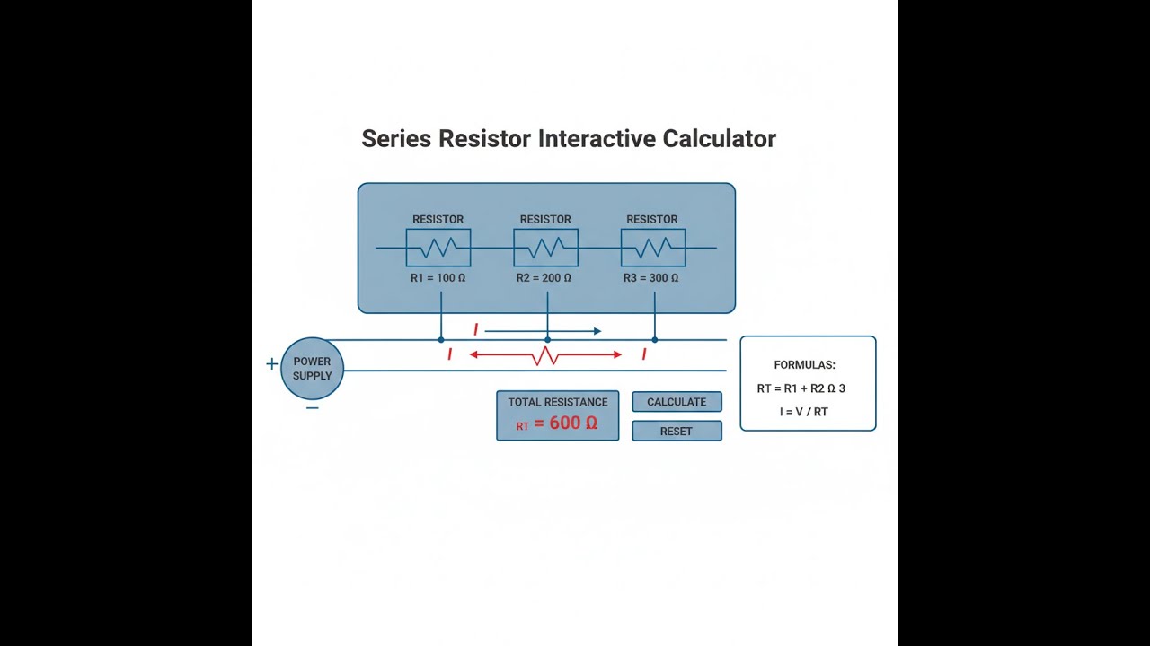
Simple Example
3 resistors in series: R₁ = 100 Ω, R₂ = 200 Ω, R₃ = 300 Ω. Supply voltage = 12 V.
Total resistance = 100 + 200 + 300 = 600 Ω
Circuit current = 12 V ÷ 600 Ω = 20 mA
Voltage drops: R₁ = 2 V, R₂ = 4 V, R₃ = 6 V (sum = 12 V ✓)
Total power = 12 V × 0.02 A = 240 mW
Theory & Practical Applications of Series Resistor Circuits
Series resistor circuits represent the most fundamental configuration in electrical engineering, where components share a single current path with no alternative routes. Unlike parallel circuits where current divides, series circuits maintain identical current through every component while distributing voltage proportionally according to each resistor's value. This characteristic makes series configurations indispensable for voltage division, current limiting, and precision measurement applications across power electronics, sensor conditioning, LED driver design, and analog signal processing.
Fundamental Series Circuit Behavior
The defining characteristic of series circuits is current continuity — the same current flows through every resistor regardless of individual resistance values. This occurs because electrons have no alternative path, and charge conservation requires input and output current to be identical at every point. The total resistance becomes the arithmetic sum of all individual resistances, making series circuits the only configuration where adding components always increases total resistance. This additive property simplifies design calculations but creates a critical vulnerability: a single open circuit anywhere in the series path interrupts current flow completely, rendering the entire circuit non-functional.
Voltage distribution in series circuits follows a precise mathematical relationship determined by the ratio of each resistor to the total resistance. This voltage division principle forms the basis for countless practical applications. Each resistor's voltage drop equals the circuit current multiplied by that resistor's value, and Kirchhoff's Voltage Law guarantees that these individual drops sum exactly to the supply voltage. This predictable voltage splitting enables resistive voltage dividers to generate reference voltages, scale sensor outputs, and create bias points for transistor circuits without requiring active regulation components.
Practical Voltage Divider Design Considerations
While the voltage divider equation appears simple, real-world implementations must account for loading effects, temperature coefficients, power dissipation limits, and noise coupling. The output voltage Vout = Vin × (R2 / (R1 + R2)) holds true only when output current is negligible compared to divider current. When a load resistor Rload connects to the divider output, it forms a parallel combination with R2, reducing effective resistance and lowering output voltage. Design practice requires divider current to exceed load current by a factor of 10 or more, a rule that becomes increasingly challenging in battery-powered systems where quiescent current must be minimized.
Temperature effects introduce voltage drift through resistor temperature coefficients, typically 50-200 ppm/°C for standard film resistors. A voltage divider experiencing 50°C temperature rise with 100 ppm/°C resistors can shift output voltage by 0.5%, unacceptable for precision applications requiring ±0.1% accuracy. High-precision voltage references use matched resistor pairs with tracking temperature coefficients, where both resistors shift identically, maintaining ratio stability even as absolute values drift. Metal foil resistors achieve ±2 ppm/°C matching, enabling dividers stable to better than 10 ppm over industrial temperature ranges, essential for ADC reference networks and precision instrumentation.
Current Limiting Applications in LED and Protection Circuits
Series resistors provide the simplest current-limiting solution for LEDs, preventing destructive overcurrent while enabling operation from higher-voltage sources. The current-limiting resistor value is calculated from R = (Vsupply - VLED) / ILED, where VLED is the LED forward voltage (typically 1.8-3.3V depending on color) and ILED is the desired operating current. For a red LED (VF = 2.0V) driven at 20 mA from a 5V supply, the required resistance is (5V - 2.0V) / 0.020A = 150Ω, with power dissipation of 60 mW requiring a minimum ¼W rated resistor for reliability.
This simple approach suffers from efficiency losses and voltage sensitivity. The resistor dissipates power equal to I²R, representing wasted energy that becomes critical in battery-powered systems. A 20 mA LED with 150Ω series resistor wastes 60 mW — three times the 20 mW consumed by the LED itself, yielding only 25% efficiency. Furthermore, LED current varies linearly with supply voltage: a 10% increase in supply voltage (5.0V to 5.5V) increases current by approximately 25% due to the flat LED V-I curve near operating voltage. This sensitivity explains why precision LED displays and automotive lighting increasingly use constant-current driver ICs rather than simple series resistors, despite higher component costs.
Sensor Signal Conditioning and Measurement Circuits
Series resistor networks form the foundation of resistive sensor interfaces, converting resistance changes from thermistors, strain gauges, and photoresistors into voltage signals suitable for ADC inputs. A thermistor in series with a fixed resistor creates a voltage divider whose output varies with temperature, enabling digital thermometry. For a 10kΩ NTC thermistor (β = 3950K) in series with a 10kΩ fixed resistor across 5V, the output voltage at 25°C is 2.5V, decreasing to approximately 1.8V at 50°C — a sensitivity of 28 mV/°C well-suited to 10-bit ADC resolution (4.9 mV/LSB).
The series resistor value critically affects sensitivity, linearity, and measurement range. Using a fixed resistor equal to the thermistor's value at mid-range temperature maximizes sensitivity at that point while maintaining reasonable linearity over ±20°C. Smaller fixed resistors shift peak sensitivity toward higher temperatures but reduce overall voltage swing; larger resistors provide the opposite effect. Precision temperature measurement over wide ranges requires multi-point calibration or piecewise linearization algorithms to correct the thermistor's exponential characteristic, typically achieving ±0.5°C accuracy over 0-100°C with careful calibration.
Power Distribution and Voltage Drop Analysis
Series resistance in power distribution wiring causes voltage drops that degrade system performance and waste energy. A 20-meter cable run carrying 10A through AWG 14 copper wire (2.525Ω per 1000 feet) creates a round-trip resistance of approximately 0.33Ω, resulting in a 3.3V drop at full current. For a 48V DC system, this represents 6.9% voltage loss, reducing load voltage to 44.7V and dissipating 33W as heat in the wiring. This calculation explains why industrial automation systems specify maximum cable lengths for given currents, and why high-power DC distribution favors higher voltages to reduce current for equivalent power transmission.
The National Electrical Code limits voltage drop to 3% for branch circuits and 5% total for combined feeder and branch circuits, ensuring adequate voltage at utilization equipment. Calculating acceptable wire size requires determining total series resistance from wire gauge tables, then verifying voltage drop meets code limits. For example, supplying a 20A, 120V AC load 50 meters from the panel requires minimum AWG 10 copper conductors (1.018Ω per 1000 feet) to maintain voltage drop below 3.6V. This constraint drives significant copper costs in large buildings, making voltage drop analysis essential during electrical design phases.
Worked Example: Multi-Stage Series Circuit Analysis
A prototype automotive sensor interface circuit uses three series resistors to condition a pressure sensor output: R1 = 2.2kΩ (current limiting), R2 = 4.7kΩ (voltage division), and R3 = 3.3kΩ (load isolation). The circuit operates from a 12.0V automotive electrical system with expected variations of ±1.5V during engine cranking events. We must determine nominal operating current, voltage at each node, individual power dissipation, and verify component ratings for worst-case maximum voltage conditions.
Step 1: Calculate total series resistance
Rtotal = R1 + R2 + R3 = 2200Ω + 4700Ω + 3300Ω = 10,200Ω = 10.2kΩ
Step 2: Determine nominal circuit current (12.0V supply)
I = Vsupply / Rtotal = 12.0V / 10,200Ω = 1.176 mA
Step 3: Calculate voltage drops across each resistor
V1 = I × R1 = 0.001176A × 2200Ω = 2.588V
V2 = I × R2 = 0.001176A × 4700Ω = 5.529V
V3 = I × R3 = 0.001176A × 3300Ω = 3.881V
Verification: 2.588V + 5.529V + 3.881V = 11.998V ≈ 12.0V ✓
Step 4: Determine node voltages (referenced to ground after R3)
Node after R1: VA = Vsupply - V1 = 12.0V - 2.588V = 9.412V
Node after R2: VB = Vsupply - (V1 + V2) = 12.0V - 8.117V = 3.883V
Ground reference: VC = 0V
Step 5: Calculate power dissipation in each resistor (nominal conditions)
P1 = I² × R1 = (0.001176)² × 2200 = 3.044 mW
P2 = I² × R2 = (0.001176)² × 4700 = 6.502 mW
P3 = I² × R3 = (0.001176)² × 3300 = 4.565 mW
Ptotal = Vsupply × I = 12.0V × 0.001176A = 14.11 mW
Verification: 3.044 + 6.502 + 4.565 = 14.111 mW ✓
Step 6: Worst-case analysis at maximum voltage (13.5V during alternator charging)
Imax = 13.5V / 10,200Ω = 1.324 mA
P1,max = (0.001324)² × 2200 = 3.855 mW
P2,max = (0.001324)² × 4700 = 8.240 mW
P3,max = (0.001324)² × 3300 = 5.784 mW
Ptotal,max = 13.5V × 0.001324A = 17.87 mW
Step 7: Component rating verification
Standard 1/8W (125 mW) resistors provide derating factor of 125mW / 8.240mW = 15.2× at worst-case conditions, well above the recommended 2× minimum derating for automotive environments with 125°C maximum ambient temperature. All voltage drops remain below typical resistor working voltages (200V+ for 1/8W rated parts), confirming adequate component selection. The circuit will reliably operate across the full automotive voltage range without component stress or thermal issues.
High-Frequency and Parasitic Effects in Series Resistor Chains
At frequencies above 10 MHz, series resistor chains exhibit non-ideal behavior from parasitic inductance and capacitance. A surface-mount 1kΩ resistor typically has 1-2 nH series inductance and 0.2-0.3 pF parallel capacitance, negligible at DC but significant at RF frequencies. The inductive reactance XL = 2πfL reaches 12.6Ω at 1 GHz for 2 nH inductance, adding 1.3% impedance increase. More critically, parasitic capacitance creates unintended AC coupling paths in series chains, where high-frequency signals bypass resistors through capacitive reactance XC = 1/(2πfC). At 100 MHz, 0.3 pF provides 5.3kΩ reactance, negligible compared to typical resistor values, but at 1 GHz this drops to 531Ω, significantly affecting high-impedance voltage dividers.
Precision RF voltage dividers require careful layout with matched parasitic elements and compensated designs. Guard traces surrounding critical nodes reduce stray capacitance to adjacent circuit elements, while ground plane cutouts minimize capacitive coupling to the reference plane. Some designs intentionally add compensating capacitors to flatten frequency response, creating complex impedance networks that maintain accurate division ratios through gigahertz frequencies. These techniques are essential in vector network analyzer (VNA) test equipment, oscilloscope probe compensation networks, and RF power measurement systems where broadband accuracy determines measurement validity.
For a comprehensive understanding of other circuit analysis tools, explore the calculator hub, which includes complementary resources for parallel resistance, RC circuits, and power calculations that frequently pair with series resistor analysis in complete system design.
Frequently Asked Questions
Free Engineering Calculators
Explore our complete library of free engineering and physics calculators.
Browse All Calculators →🔗 Explore More Free Engineering Calculators
- LED Resistor Calculator — Current Limiting
- Wheatstone Bridge Calculator
- I2C/SPI Bus Speed & Pull-up Resistor Sizing
- Resistor Color Code Calculator
- Capacitive Reactance Calculator
- Resonant Frequency Lc Calculator
- Conductivity To Resistivity Calculator
- Voltage Divider Calculator
- Transformer Turns Ratio Calculator
- Voltage Divider Calculator — Output Voltage from Two Resistors
About the Author
Robbie Dickson — Chief Engineer & Founder, FIRGELLI Automations
Robbie Dickson brings over two decades of engineering expertise to FIRGELLI Automations. With a distinguished career at Rolls-Royce, BMW, and Ford, he has deep expertise in mechanical systems, actuator technology, and precision engineering.
Need to implement these calculations?
Explore the precision-engineered motion control solutions used by top engineers.


