If you’re working on optical layouts, solar panels, radar antennae, or anything involving waves hitting surfaces, the angle at which they hit will dictate what happens next. Get it wrong and you waste energy, miss useful thresholds like total internal reflection, or throw your system off in ways that are rarely obvious at the start. This calculator lets you work out the angle of incidence, refraction, critical angle, Brewster’s angle, or refractive index using basic trigonometry or Snell’s Law. The angle of incidence matters anywhere that light, RF, or sound meets something: positioning photovoltaics, designing light paths in fiber, setting up antennas, or even tuning the sound in a concert hall. You’ll find the key formulas, a worked solar panel example, and an FAQ at the bottom.
What is angle of incidence?
The angle of incidence is the angle between the direction a wave is coming from (light, sound, or RF) and the normal—a line drawn perpendicular to the surface at the impact point. Nearly everything about reflection, transmission, or trapping of energy at a boundary starts at this angle.
Simple Explanation
Picture shining a flashlight at a mirror. If you’re aiming straight at it, the light comes straight back—that’s 0° incidence. Tilt the flashlight and the spot sweeps off at the same angle. “Angle of incidence” is just how far from perpendicular your beam strikes the surface. The sharper the angle, the more you’ll see effects like greater reflection, greater refraction, or simple blockage.
📐 Browse all 1000+ Interactive Calculators
How to Use This Calculator
- Pick what you want to calculate—angle, refraction, critical angle, Brewster’s angle, or refractive index.
- Input the required values for your choice. This could be distances (for geometry) or angle and refractive indices (for Snell’s Law modes).
- Watch your ranges: keep angles between 0° and 90°, and refractive indices positive.
- Click Calculate for your answer.
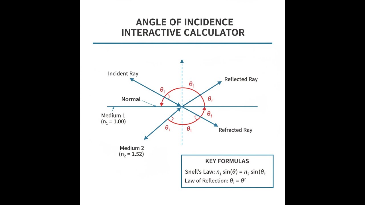
Angle of Incidence Diagram

Interactive Angle of Incidence Calculator
This calculator is intended for education, concept evaluation, and preliminary design. Results are based on the equations and assumptions described on this page, but cannot account for every real-world load case, tolerance, material property, environmental condition, installation detail, safety factor, code, or regulatory requirement. Verify all inputs, assumptions, units, and results independently before selecting components or using the result in a real application. Safety-critical, structural, medical, lifting, transportation, or regulated applications must be reviewed by a qualified engineer.
Angle of Incidence Interactive Visualizer
You can visualize how different incident angles affect reflection and refraction. Adjust the incident angle and see in real time how both reflected and refracted rays change paths. The visualization also updates critical and Brewster’s angles as you move the sliders.
REFRACTION ANGLE
19.5°
CRITICAL ANGLE
41.8°
BREWSTER ANGLE
56.3°
REFLECTION
PARTIAL
FIRGELLI Automations — Interactive Engineering Calculators
Equations & Variables
Here are the main formulas for calculating angle of incidence, refraction angle, critical angle, and Brewster’s angle.
Angle from Geometry:
θi = arctan(h / d)
Snell's Law (Refraction):
n1 sin(θi) = n2 sin(θt)
Critical Angle:
θc = arcsin(n2 / n1)
(valid only when n1 > n2)
Brewster's Angle:
θB = arctan(n2 / n1)
Variable Definitions
- θi = Angle of incidence (degrees or radians) — angle between incident ray and surface normal
- θr = Angle of reflection (degrees or radians) — always equals θi by law of reflection
- θt = Angle of refraction/transmission (degrees or radians) — angle of refracted ray from normal
- θc = Critical angle (degrees or radians) — minimum incident angle for total internal reflection
- θB = Brewster's angle (degrees or radians) — angle at which reflected light is perfectly polarized
- n1 = Refractive index of incident medium (dimensionless) — typically air = 1.00
- n2 = Refractive index of transmitted medium (dimensionless) — glass ≈ 1.5, water ≈ 1.33
- h = Vertical height or perpendicular distance (meters)
- d = Horizontal distance from normal (meters)
Simple Example
Suppose a light ray goes from air (n₁ = 1.0) into glass (n₂ = 1.5) at 45° incidence. Snell’s Law gives 1.0 × sin(45°) = 1.5 × sin(θₜ), so sin(θₜ) = 0.4714. θₜ = 28.1°. The ray bends toward the normal—16.9°—as it enters glass.
Theory & Practical Applications
Fundamental Physics of Incidence Angles
At any boundary, what the wave does—reflect, bend, or get absorbed—depends on this angle. Whenever a wave hits a change in material, you’re dealing with reflection, refraction, and sometimes absorption. The math (Snell's Law and law of reflection) is a result of matching up phase and making sure energy isn’t lost to magic. In real hardware, the influence of angle goes further—things like polarization (Fresnel equations), fiber optics limits, antenna gain versus elevation, or even how much solar energy a panel really gets, are all linked to getting the angles right.
One point that’s easy to miss—use the local normal, not just the obvious “angle,” especially on curved or rough parts. A small local deviation from expected angle at the site of incidence can cause bigger-than-expected swings in system performance. On solar panels, for example, a few degrees in mounting tolerance can hit output much harder at steep sun angles than at midday. It’s nonlinear—missing by 10° at a 60° zenith is much worse than missing by 10° near the middle of the day. Run the numbers if you’re specifying tolerances where performance matters.
Snell's Law and Refractive Index Variations
Snell’s Law (n₁ sin(θᵢ) = n₂ sin(θₜ)) is what you use at a clean, flat interface—but actual setups vary. Refractive index depends on wavelength, which leads to effects like chromatic aberration in optics or rainbows in nature. If your project needs more precision (say, laser work at a known wavelength), watch the details—databooks or Sellmeier equations give wavelength-specific values. For fiber optics, small tolerances in refractive index difference between core and cladding change the acceptance angle and mode propagation more than most first-time designers expect. Also, refractive index changes somewhat with temperature—account for this when tight tolerances are required or if your assemblies will see big temperature swings.
Total internal reflection (TIR) happens when light tries to leave a denser (higher-index) material at a steep angle. Use θc = arcsin(n₂/n₁), but only if n₁ > n₂. TIR is how fiber optics, retroreflectors, and prism-based binoculars work. But even with TIR, some energy leaks into the lower-index medium over a short range (evanescent wave), which can become a loss path if something else is very close. Engineers sometimes exploit this for special optical couplers, but usually it’s just a small, hard-to-eliminate loss.
Brewster's Angle and Polarization Effects
Brewster’s angle (θB = arctan(n₂/n₁)) is where you get zero reflection for p-polarized light (when the electric field is in the plane of incidence). At this angle, the reflected and refracted rays are 90° apart and the reflected electric field would point along its direction of travel—so no reflection happens for that polarization. Perpendicular (s) polarization still reflects, so the reflected light at this angle is highly polarized.
In practical terms, this matters for coatings on laser optics (minimizing reflection losses for a known polarization), for photographers using polarizing filters to cut glare, and for architectural glass. When designing these systems, remember what direction and geometry the main light comes from—it’s not always straight on, and real-world incident angles drift all over depending on time of day or field of view.
Solar Energy Applications and Cosine Losses
Two things kill solar panel efficiency as the sun moves off normal: the cosine loss (how much less light hits per area), and reflectance (how much bounces off the glass). The cosine loss is just cos(θᵢ)—at 60°, you’re down to 500 W/m² from 1 kW/m² even before factoring in reflection. Fixed arrays are typically tilted close to local latitude for yearly average yield, but that’s a tradeoff between summer, winter, and day length. Seasonal differences are big if you don’t track.
Glass reflectance also gets worse at higher angles. Typical solar glass reflects 4% at 0°, but jumps to 12% at 60°, and more at steeper angles. Coatings can help but are mostly optimized for light near 0°. This means real yield drops off quickly at sunrise/sunset, no matter how efficient your panels are. Trackers avoid most of that, but the added mechanics mean more maintenance and cost.
Optical Fiber and Total Internal Reflection
Optical fibers use total internal reflection to keep light in the core. The maximum entry angle, set by the fiber’s numerical aperture (NA = √(n₁² - n₂²)), is small—6-7° for single-mode at telecom wavelengths, larger for multimode, which allows more rays (modes) to propagate. In multimode fibers, rays at different angles take longer or shorter paths—this spreads pulses out (modal dispersion), which limits bandwidth over long runs. There’s no free lunch; the more modes, the more dispersion, unless you go to graded-index fiber to compensate.
Worked Example: Solar Panel Array Optimization
Problem: You’ve got a solar array in Denver (39.74°N), fixed-tilt, glass is n = 1.52. Find the best year-round tilt, critical angle for glass-to-air TIR, and the early morning output loss on June 21 when the Sun is low and far east of due south.
Part A: Optimal Tilt Angle
Most installers just match tilt to latitude. That’s ~40°, which works as a solid starting point for fixed arrays.
Part B: Critical Angle for Back Surface TIR
Back-side TIR (glass-to-air) becomes a concern if light reflects inside. θc = arcsin(1.00/1.52) ≈ 41.14°. Anything steeper locks light inside the glass until absorbed or diffused elsewhere.
Part C: Angle of Incidence Calculation
With the Sun at elevation 23.6°, azimuth 67° east of due south, panel at 40° tilt, due south azimuth, you can plug into the cosine formula: cos(θᵢ) = sin(23.6°)cos(40°) + cos(23.6°)sin(40°)cos(67°) → cos(θᵢ) ≈ 0.3066 + 0.2301 = 0.5367 → θᵢ = arccos(0.5367) ≈ 57.53°
Part D: Cosine Loss and Reflectance Loss
Cosine loss: 536.7 W/m² hits the panel (from 1000 W/m²). Fresnel losses at this angle are about 11.3% (approx., varies with spectrum and glass type), so 0.887 × 536.7 ≈ 476.0 W/m² actually gets into the silicon.
Part E: Comparison to Normal Incidence
If you had the Sun head-on, you’d get about 960 W/m² after reflection (4% Fresnel loss at 0°). At the steeper morning angle, you’ve lost over half—shows why panel output craters on fixed arrays at high incidence angles.
Antenna and RF Applications
For antennas, incidence angle affects how much gain you actually get in the direction you care about. Most gain patterns drop fast after 40-50° off center, especially for patch or array antennas. Pointing error, even by a few degrees, can matter for satellite comms. On the ground, reflections off the earth create interference patterns; the angle sets where those destructive nulls show up. For cell towers, both height and downtilt are chosen with these angles in mind.
At grazing incidence, RF ground bounce can create dead zones if you’re not careful—keep transmitter/receiver heights and separation in proportion, or model your coverage to avoid surprises.
Architectural Acoustics and Sound Reflection
Sound (like light) reflects and refracts at boundaries. In auditoriums, wall angles are set to control where early reflections land. Flat walls cause focused echoes, rough/diffuse walls scatter sound. Key acoustic decisions—when a wall should reflect or spread sound—depend on sound wavelength and panel angle. Underwater, the air/water boundary acts as a near-total reflector for almost all incident angles, which is why it’s so hard to hear submerged sources from above water.
Frequently Asked Questions
Free Engineering Calculators
Explore our complete library of free engineering and physics calculators.
Browse All Calculators →🔗 Explore More Free Engineering Calculators
About the Author
Robbie Dickson — Chief Engineer & Founder, FIRGELLI Automations
Robbie Dickson brings over two decades of engineering expertise to FIRGELLI Automations. With a distinguished career at Rolls-Royce, BMW, and Ford, he has deep expertise in mechanical systems, actuator technology, and precision engineering.
Video Walkthrough - How to Use This Calculator
Need to implement these calculations?
Explore the precision-engineered motion control solutions used by top engineers.


