Building an Affordable Boat Autopilot System
For serious anglers and recreational boaters, maintaining a steady course while trolling or navigating open water is essential—but commercial autopilot systems can easily cost $2,000 to $5,000 or more. What if you could build a fully functional autopilot system for under $350? By combining a 12V DC linear actuator with open-source Arduino-based control electronics, it's entirely possible to create a reliable steering system that rivals commercial offerings at a fraction of the cost.
This comprehensive guide walks through the complete process of designing and installing a DIY boat autopilot system using electric linear actuation. Whether you're steering a single outboard motor or coordinating a main engine with a trolling motor, this project demonstrates how precision motion control technology can be adapted for marine applications. The system featured here uses a 9-inch stroke actuator paired with Jack Edwards' Arduino-based autopilot software, offering both magnetic heading mode and manual joystick control.
The key to success lies in careful measurement, proper mechanical linkage design, and understanding how linear actuators translate electrical signals into precise mechanical movement. While this project requires fabrication skills and basic electronics knowledge, the result is a highly customizable autopilot system that can be adapted to virtually any boat configuration.
Selecting the Right Linear Actuator for Marine Steering
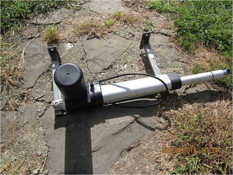
The foundation of any electric steering system is the actuator itself. For this marine autopilot application, a 12V DC actuator with a 9-inch stroke length was selected—specifically a deluxe model designed to handle the forces involved in steering an outboard motor. The choice of stroke length is critical and must be determined before purchasing components.
When selecting an actuator for boat steering, consider these essential specifications:
- Stroke Length: This determines how far the actuator can extend and retract, which directly correlates to the steering range. Measure your outboard motor's full left-to-right travel range before selecting a stroke length. A 9-inch stroke typically provides adequate range for most outboard installations, while a 12-inch stroke may result in over-travel issues.
- Force Rating: Outboard motors can require significant force to turn, especially at higher speeds or in rough water. A deluxe model actuator typically offers 200-400 lbs of force, which is appropriate for most recreational boat applications.
- Voltage: Marine applications almost universally use 12V DC systems, matching standard boat electrical systems.
- Built-in Limit Switches: These internal switches automatically stop the actuator at full extension and retraction, protecting the motor from damage and ensuring reliable operation.
- Duty Cycle: For autopilot applications requiring frequent corrections, select an actuator rated for higher duty cycles to ensure longevity.
The deluxe model used in this project includes internal limit switches that prevent over-travel—a critical safety feature. When the actuator reaches either end of its stroke, these switches automatically cut power, preventing motor damage. This feature is only effective when the mechanical linkage is properly dimensioned, which we'll cover in the fabrication section.
Fabricating the Actuator Mounting System
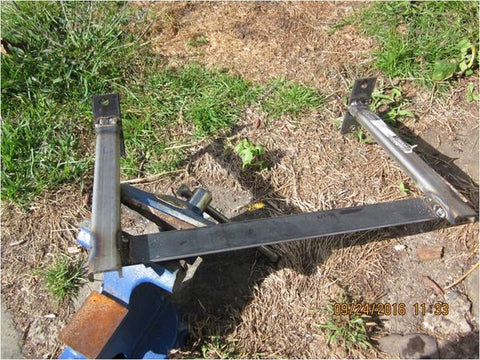
The mechanical mounting system requires two custom brackets: one to attach the actuator to the boat's transom, and another to connect the actuator to the outboard motor. Both brackets must allow pivoting movement to accommodate the sweeping arc of the steering motion while maintaining structural rigidity under load.
Transom Mounting Bracket
The transom bracket serves as the fixed anchor point for the linear actuator. Fabricated from steel for durability in the marine environment, this bracket must be designed with several critical considerations:
First, account for outboard motor tilt functionality. Many installations initially overlook this requirement, necessitating rework when the motor cannot tilt properly for trailering or shallow water operation. The bracket should be positioned to allow full tilt range without interference from the actuator assembly.
The actuator attachment point should use a chrome spacer and bolt from a marine or hardware supplier, creating a pivot point that allows the actuator to maintain proper alignment as it drives the motor through its arc. This pivot is essential—without it, the actuator would bind or create excessive side loads that could damage internal components.
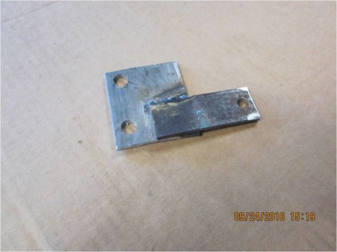
Outboard Motor Connection Bracket
The motor-side bracket connects to the outboard's steering arm and provides an attachment point for the quick-disconnect linkage. This bracket typically requires trial-and-error refinement to achieve proper clearance throughout the full range of motion.
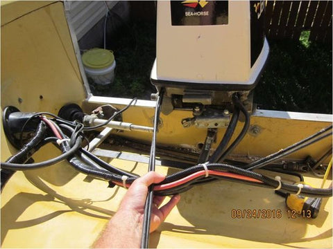
A critical modification for this installation involves replacing the manual steering attachment bolt with a hitch pin. This simple change allows quick disconnection of the manual steering cable when operating under autopilot control. The manual cable creates excessive friction that can overwork the actuator and drain battery power unnecessarily. The hitch pin enables tool-free reconnection if the autopilot system fails and manual steering becomes necessary.
The bracket should incorporate a quick-disconnect ball socket (such as those from Panther Marine) that accepts a threaded rod end. This connection method allows the actuator force to be transmitted to the motor while maintaining the freedom of movement necessary for proper operation. The ball joint accommodates the complex geometry changes that occur as the motor swings through its arc.
Actuator End Mounting Hardware
The actuator's extension rod requires its own pivot mounting to maintain alignment. A U-bolt, modified into a square shape using heat and a hammer, creates an effective mounting cradle. Insert a section of PVC pipe between the actuator rod and the U-bolt to allow the actuator to slide and rotate slightly within the mount—this accommodation prevents binding and side-loading as the geometry changes throughout the steering motion.
The U-bolt should be tightened enough to prevent excessive play but loose enough to allow smooth sliding movement on the PVC pipe. This detail is often overlooked but is essential for long-term reliability and smooth operation.
Critical Measurements and Linkage Fabrication
The most challenging aspect of this installation involves determining the correct length for the quick-disconnect link rod that connects the actuator to the outboard motor bracket. This dimension is absolutely critical—incorrect length will prevent the actuator's internal limit switches from functioning properly, potentially causing premature wear or failure.
Measuring for Proper Linkage Length
Follow this precise measurement procedure to determine the correct link length:
- Fully extend the actuator and mark the center point of its stroke on the extension rod. For a 9-inch stroke actuator, this mark should be at 4.5 inches of extension.
- Position the outboard motor in its center position—pointing straight ahead.
- With the actuator set at its half-extension point (4.5 inches in this example), measure the distance from the actuator's rod end hole to the ball socket on the motor bracket.
- This measured distance is your required link length. In the example installation, this measurement was 9.75 inches.
The importance of this measurement cannot be overstated. When properly dimensioned, the outboard motor will reach its full left and right steering limits precisely when the actuator reaches its internal limit switches. If the link is too short, the motor will hit its mechanical stops before the actuator reaches its limits, and the motor will continue trying to drive, wearing out prematurely. If too long, the outboard won't achieve its full steering range.
Fabricating the Quick-Disconnect Link
The link itself is fabricated from hollow steel tubing with Grade 8 fine-thread bolts welded to each end. The bolt heads are removed, allowing the bolts to slide inside the tubing before welding. This creates a strong, clean connection point that accepts rod end bearings or ball socket hardware.
The quick-disconnect design allows tool-free removal of the link when switching from autopilot to manual steering, or when performing maintenance. Using quality marine hardware from suppliers like Panther Marine ensures corrosion resistance and long-term reliability in the harsh saltwater environment.
Dual Motor Installations
For boats equipped with both a primary outboard and a kicker or trolling motor, a longer quick-disconnect link can be fabricated to drive both motors simultaneously. This arrangement provides superior rudder authority during trolling operations, especially in wind or waves. The dual-motor setup can be quickly reconfigured to raise the kicker motor and operate only the main outboard when desired.
Arduino-Based Control Electronics
The electronic control system forms the brain of the autopilot, translating sensor inputs into precise motor control commands. This installation uses Jack Edwards' open-source Arduino-based autopilot design, which offers remarkable functionality for minimal cost. The complete electronics package, including the Arduino Mega 2560, sensors, and motor driver, costs approximately $100-150.
Core Components and Architecture
The control system consists of several key components:
- Arduino Mega 2560: The main microcontroller board that runs the autopilot software and coordinates all system functions. The Mega's expanded I/O capability compared to smaller Arduino boards makes it ideal for this application.
- BNO055 Magnetic Heading Sensor: A 9-axis absolute orientation sensor that provides precise magnetic heading data for course-keeping functionality. This IMU (Inertial Measurement Unit) combines a magnetometer, accelerometer, and gyroscope for accurate heading detection even in rough seas.
- Pololu Qik PWM Motor Driver: A pulse-width modulation motor controller that drives the actuator with variable speed based on heading error. PWM control allows proportional response—the actuator drives faster when further off course and slower as it approaches the target heading.
- Keypad Interface: A simple membrane keypad ($4.95 from Amazon) provides mode selection and setting adjustment. Minor wiring modifications may be necessary to match the specific keypad model to Jack Edwards' software expectations.
- Potentiometer Knob: Enables manual "knob steering" mode where the autopilot maintains the heading set by turning the potentiometer—useful for fine course adjustments without changing the magnetic heading reference.
- Mode Selection Toggle Switch: Allows switching between manual joystick control and autopilot modes.
- Joystick Controller: Provides direct manual control of the actuator for docking and close-quarters maneuvering.
Assembly and Wiring
Jack Edwards provides comprehensive fritzing diagrams (pictorial wiring diagrams) that show exactly which wire connects where—these are far more useful than traditional schematic diagrams for builders without electronics backgrounds. The software and wiring diagrams are available through his Dropbox repository.
Rather than using an Arduino shield interface board, wires can be connected directly to the Arduino Mega's header pins using pre-crimped ribbon cable connectors. This simplifies the build and reduces cost. The various sensor boards and motor driver require soldered connections, necessitating basic soldering skills, 60/40 rosin core solder, and a soldering iron.
Critical safety note: Install inline fuses on all power connections to protect both the electronics and the boat's electrical system. Use marine-grade wire and connectors throughout, and seal all electrical connections against moisture intrusion.
Software Configuration and Tuning
Jack Edwards' autopilot software includes several adjustable parameters that can be tuned for optimal performance with different actuator and boat combinations. Two parameters are particularly important:
Motor Speed Minimum (motorspeed_min): This parameter determines how much heading error must exist before the actuator begins to drive. In code version J11, this appears at line 378. The default setting of 30 means the boat must be 30 degrees off course before the actuator activates—far too large for practical use. Jack suggests setting this to 127 for full motor drive with any error, but a value around 75 provides good response (approximately 3 degrees of error triggers actuator movement) without excessive activity.
Deadband Setting: Set to 2 degrees by default, this creates a "neutral zone" where the autopilot doesn't respond to minor heading variations caused by waves and wind. This prevents constant actuator cycling that would drain the battery and wear components unnecessarily. The default 2-degree deadband works well for most conditions.
These settings may require on-water testing and fine-tuning to optimize performance for your specific boat, actuator, and typical operating conditions. Keep a laptop with the Arduino IDE available for the first few trips to make adjustments based on real-world performance.
Future Expansion: GPS Waypoint Steering
The Jack Edwards autopilot design supports GPS waypoint steering capability with the addition of another Arduino board (approximately $56) and a compatible GPS module. This upgrade enables the autopilot to automatically steer toward GPS coordinates, following a programmed route—invaluable for offshore fishing or cruising applications. The magnetic heading mode alone provides excellent course-keeping capability, but GPS steering represents a significant functional upgrade for minimal additional investment.
Installation Tips and Operational Considerations
Power Supply and Battery Considerations
The actuator draws significant current during operation, potentially 5-10 amps depending on load. Ensure your boat's electrical system can support this additional load, and consider the impact on battery capacity during extended trolling sessions. A dedicated deep-cycle marine battery for the autopilot system may be warranted for boats that spend long hours under autopilot control.
The Arduino and sensor electronics draw minimal current (typically under 500mA), but the motor driver and actuator represent substantial loads. Monitor battery voltage during operation and ensure your charging system (alternator or onboard charger) can maintain adequate voltage under load.
Weatherproofing and Marine Environment Protection
Marine environments are exceptionally harsh on electronics and mechanisms. All electrical connections should be sealed with marine-grade heat shrink tubing or liquid electrical tape. Consider housing the Arduino and driver electronics in a weatherproof enclosure with cable glands for wire entry.
The actuator itself should be a model with appropriate environmental protection—marine-grade industrial actuators offer better sealing and corrosion resistance than economy models. Regular inspection and maintenance of mechanical connections, particularly the ball joints and mounting brackets, will prevent corrosion-related failures.
System Redundancy and Safety
The quick-disconnect design ensures that manual steering can be rapidly restored if the autopilot system fails. Always test manual steering reconnection before leaving the dock, and keep the hitch pin and any required tools readily accessible.
Install a clearly labeled emergency shutoff switch that kills power to the autopilot system. This allows instant return to manual control without needing to physically disconnect the linkage in an emergency situation.
Break-In and Testing Procedures
Initial testing should be conducted in calm, open water with minimal traffic. Verify that:
- The actuator reaches its limit switches before the outboard motor hits mechanical stops
- Manual steering disconnects and reconnects smoothly
- The autopilot maintains heading within acceptable tolerances
- All electrical connections remain secure and dry
- Battery voltage remains adequate under extended operation
- The system responds appropriately to course changes and heading adjustments
Make software adjustments based on actual performance, documenting the parameter values that provide optimal results for future reference.
Cost Breakdown and Component Sourcing
One of the most compelling aspects of this project is the dramatic cost savings compared to commercial autopilot systems. Here's an approximate breakdown:
- 12V DC Linear Actuator (9-inch stroke, deluxe model): $150-200
- Arduino Mega 2560: $35-50
- BNO055 Orientation Sensor: $35-45
- Pololu Qik Motor Driver: $40-50
- Keypad, Joystick, Potentiometer: $15-25
- Steel Stock, Bolts, Hardware: $20-30
- Quick-Disconnect Ball Joints (Panther Marine): $25-40
- Marine Wire, Connectors, Fuses: $15-25
- Miscellaneous (heat shrink, solder, etc.): $10-15
Total project cost: approximately $300-350, depending on component sources and whether you have some materials on hand. This represents roughly 10-15% of the cost of a comparable commercial autopilot system, with the added benefits of customization and expandability.
Advantages Over Commercial Autopilot Systems
Beyond cost savings, the DIY approach offers several compelling advantages:
Customization: The system can be tailored to your exact boat configuration, including dual-motor setups that commercial systems may not support. Software parameters can be tuned for your specific needs rather than accepting one-size-fits-all factory settings.
Expandability: Adding GPS waypoint steering or additional features requires only modest investment and can be done incrementally as budget allows. The open-source software foundation means new capabilities can be added as they're developed by the community.
Serviceability: You understand every component of your system and can troubleshoot or repair it without specialized tools or proprietary knowledge. Replacement parts are readily available from standard suppliers rather than requiring expensive marine-specific components.
Learning Experience: Building the system provides deep understanding of how autopilot systems work, making you a more capable boat operator and mechanic. This knowledge transfers to other boat systems and DIY projects.
Common Challenges and Solutions
Binding and Mechanical Interference
The most common issue during installation is mechanical binding or interference between components. This typically manifests as jerky actuator movement, excessive current draw, or the actuator stalling before reaching its limits. Solutions include:
- Ensuring all pivot points move freely without excessive play
- Verifying that no components contact each other throughout the full range of motion
- Adjusting the quick-disconnect link length if binding occurs at the extremes of travel
- Adding shims or spacers to correct alignment issues
Electrical Noise and Sensor Interference
The high-current motor driver can generate electrical noise that interferes with the sensitive compass sensor. If the heading reading appears erratic or jumpy, try:
- Physically separating the BNO055 sensor from the motor driver and high-current wiring
- Using shielded cable for sensor connections
- Adding filter capacitors to the motor power supply
- Ensuring all grounds are properly connected to a common point
Actuator Overheating or Duty Cycle Issues
If the actuator becomes excessively hot during operation, it may be working harder than necessary due to:
- Excessive friction from the manual steering cable still connected
- Mechanical binding in the linkage
- Software settings causing constant correction cycling
- An actuator with insufficient force rating for your motor
Always disconnect the manual steering cable during autopilot operation, and consider upgrading to a higher-duty-cycle actuator if overheating persists after addressing mechanical issues.
Frequently Asked Questions
What size actuator do I need for my outboard motor?
Actuator selection depends on two primary factors: stroke length and force rating. Stroke length should match your outboard's steering range—typically 9-12 inches for most recreational boats. Measure your motor's full lock-to-lock travel before ordering. For force rating, most outboards up to 90-115 HP can be controlled with a 200-400 lb actuator. Larger motors or high-speed applications may require higher force ratings. The key is selecting a deluxe model linear actuator with built-in limit switches and appropriate duty cycle for marine use.
Can this autopilot system work with hydraulic steering?
Yes, but the installation becomes more complex. Rather than connecting directly to the outboard motor's steering arm, you would need to drive the hydraulic steering pump or attach to the steering wheel shaft. Some builders have successfully adapted this system for hydraulic steering by using a larger actuator to physically turn the steering wheel or by integrating with the hydraulic system through a custom adapter. The electronic control system remains the same, but the mechanical interface requires significant modification.
How accurate is the Arduino autopilot compared to commercial systems?
When properly tuned, Jack Edwards' Arduino autopilot can maintain heading within 2-3 degrees in moderate conditions—comparable to mid-range commercial systems. The BNO055 sensor provides highly accurate heading data, and the PWM motor control allows proportional response. Real-world accuracy depends on proper installation, software tuning, sea conditions, and boat characteristics. Some commercial systems may offer faster response times or more sophisticated algorithms, but for most recreational applications, the DIY system performs admirably.
What happens if the autopilot fails while underway?
The quick-disconnect design ensures you can rapidly return to manual steering. Simply disconnect the actuator linkage using the quick-disconnect ball joints, reconnect the manual steering cable using the hitch pin, and resume normal manual operation. This switchover can be accomplished in under a minute. It's recommended to practice this procedure dockside before relying on the autopilot in open water. Always maintain the ability to quickly revert to manual steering in case of electrical failure or other issues.
Can I add GPS waypoint steering later?
Absolutely. The Jack Edwards autopilot software is designed to support GPS waypoint steering as an add-on capability. You'll need to add another Arduino board (approximately $56), a compatible GPS module, and upload the GPS-enabled version of the software. The existing wiring and mechanical installation remain unchanged. This incremental upgrade path allows you to start with basic magnetic heading mode and add advanced navigation features as your budget and needs dictate. Full GPS waypoint steering enables the autopilot to automatically navigate to saved coordinates or follow a programmed route.
How long will the actuator last in a marine environment?
Actuator lifespan in marine applications depends on duty cycle, environmental protection, and maintenance. A quality marine-grade actuator with proper sealing should provide several seasons of reliable service with appropriate care. Key factors for longevity include disconnecting the manual steering cable to reduce load, ensuring the linkage geometry prevents binding and side-loading, protecting electrical connections from moisture, and performing regular inspections for corrosion. Some builders report 3-5+ years of service from properly installed systems. Using industrial actuators with higher IP ratings and corrosion-resistant materials significantly extends service life in harsh saltwater environments.
Do I need special tools to build this system?
Basic metalworking and electronics tools are sufficient for most builders. Required tools include: a drill and drill bits for mounting holes, wrenches and sockets for assembly, a MIG or stick welder for fabricating brackets (or you can have brackets welded at a local shop), a soldering iron and solder for electronics assembly, wire strippers and crimpers for electrical connections, and a MAP gas torch if you're shaping the U-bolt mount. Basic hand tools like hacksaws, files, and measuring tools round out the requirements. If you lack welding equipment, consider having the steel brackets fabricated by a local welding shop based on your measurements—the cost is typically $50-100 and ensures strong, clean welds.
Will this drain my boat battery?
The autopilot system does draw power, but consumption is manageable with proper setup. The Arduino and sensors draw minimal current (under 0.5A), while the actuator may draw 5-10 amps when actively moving. However, the actuator only operates intermittently to make heading corrections—it's not running continuously. In practice, a typical trolling session might average 1-2 amps of consumption. On a boat with a healthy charging system (alternator running), this poses no issue. For extended trolling on a kicker motor without alternator charging, monitor battery voltage and consider a dedicated deep-cycle battery for the autopilot system. Disconnecting the manual steering cable significantly reduces actuator load and power consumption.


