Achieving synchronized motion between multiple linear actuators is critical in applications ranging from automated trapdoors and lift platforms to adjustable furniture and robotic systems. When two or more actuators must move in perfect unison — whether opening a hatch evenly, raising a platform level, or maintaining symmetry in a kinetic sculpture — slight differences in load, friction, or manufacturing tolerances can cause them to drift out of sync. The result? Binding, uneven force distribution, premature wear, and potential system failure.
For commercial installations and applications requiring reliable, plug-and-play operation, FIRGELLI Automations offers dedicated synchronous control boxes like the FA-SYNC-2 and FA-SYNC-4, which provide hardware-based synchronization without programming. However, for makers, engineers, and DIY enthusiasts who need custom control logic, adjustable parameters, or integration with larger automation systems, an Arduino-based solution offers unparalleled flexibility and learning opportunities.
This comprehensive guide demonstrates how to achieve synchronous control of two linear actuators using an Arduino microcontroller, feedback actuators with optical encoders, and basic proportional control algorithms. We'll cover the theory behind encoder-based position tracking, provide complete calibration and control code, and discuss practical considerations for real-world implementation including debouncing, load compensation, and system tuning.
Understanding Synchronous Control Fundamentals
Synchronous control maintains equal extension between multiple actuators by continuously comparing their positions and adjusting motor speeds accordingly. Unlike open-loop systems that simply apply the same voltage to multiple actuators (which inevitably drift due to manufacturing variations and load differences), closed-loop synchronous control uses position feedback to actively correct any discrepancies.
The basic principle is straightforward: if one actuator extends faster than its counterpart, the control system reduces its speed while potentially increasing the speed of the lagging actuator. This continuous adjustment happens many times per second, keeping both actuators within a few millimeters of each other throughout the entire stroke length.
Why Actuators Fall Out of Sync
Several factors cause actuators to drift when controlled identically:
- Manufacturing tolerances: No two actuators are perfectly identical in internal friction, gear efficiency, or motor characteristics
- Uneven loading: Different weight distribution across a platform means one actuator works harder than the other
- Voltage drop: Longer wire runs or poor connections can reduce effective voltage to one actuator
- Temperature effects: Internal friction and motor performance vary with temperature during operation
- Wear and aging: Components wear at different rates over the actuator's lifetime
Encoder-based feedback systems compensate for all these variables by measuring actual position rather than assuming it based on input signals.
How Optical Encoders Enable Position Tracking
The FIRGELLI Optical Series linear actuators feature an integrated optical encoder that provides precise position feedback. Understanding how this encoder works is essential for implementing effective synchronous control.
Optical Encoder Operation
The optical encoder consists of three main components:
- Perforated disk: A plastic disk with 10 evenly-spaced holes, mechanically coupled to the DC motor shaft
- Infrared LED: Positioned on one side of the disk to provide consistent illumination
- Infrared phototransistor: Positioned opposite the LED to detect transmitted light
As the motor rotates, the disk spins between the LED and sensor. When a hole aligns with the light path, the sensor detects transmitted light and outputs a high signal. When solid plastic blocks the path, the output goes low. This creates a square wave signal where each pulse represents a precise increment of motor rotation.
Encoder Resolution Specifications
The number of pulses per inch varies by actuator force rating:
- 35 lb capacity actuators: 50 pulses per inch (±5 pulse tolerance)
- 200 lb capacity actuators: 100 pulses per inch (±5 pulse tolerance)
- 400 lb capacity actuators: 100 pulses per inch (±5 pulse tolerance)
The tolerance range means that calibration is essential — two supposedly identical actuators may have slightly different pulse counts for the same stroke length. This is why the calibration procedure is a critical first step before attempting synchronous control.
Required Components and Hardware Setup
This project requires specific hardware components to interface the actuators with the Arduino and provide adequate power supply capacity.
Essential Components
- Two optical linear actuators: Any FIRGELLI Optical Series actuator with encoder output
- Arduino Uno: Or compatible board with at least two hardware interrupt pins
- Two IBT-2 motor drivers: High-current H-bridge modules rated for 43A continuous, capable of PWM speed control
- 12V power supply: Minimum 5A capacity recommended for dual actuator operation
- Three momentary pushbuttons: For extend, retract, and stop commands
- Connecting wires: Appropriate gauge for current requirements (18-22 AWG recommended)
- Optional potentiometer: 10kΩ linear taper for real-time control tuning
Why IBT-2 Motor Drivers
The IBT-2 module uses the BTS7960 high-power motor driver chip and provides several critical features:
- High current capacity: 43A continuous operation handles actuator stall conditions
- PWM speed control: Accepts standard Arduino PWM signals for proportional speed adjustment
- Thermal protection: Built-in overtemperature shutdown prevents damage
- Direction control: Separate enable pins for forward and reverse operation
- Opto-isolation: Electrically isolates control signals from motor power
Wiring Diagram and Connections
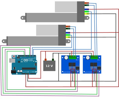
Critical wiring notes:
- Always verify actuator wire colors against your specific model's documentation — color conventions may vary
- Connect the encoder signal wires to Arduino pins 2 and 3 (the Uno's hardware interrupt pins)
- Use separate power and ground connections for motor driver logic (5V from Arduino) and motor power (12V supply)
- Ensure all grounds are connected together (common ground between Arduino, drivers, and power supply)
- Keep encoder signal wires away from motor power wires to minimize electrical noise
- Use adequate wire gauge for the 12V power connections to prevent voltage drop under load
Calibration Procedure: Establishing Baseline Pulse Counts
Before synchronous control can function accurately, you must determine the exact number of encoder pulses each actuator generates over its full stroke. This compensates for the ±5 pulse per inch manufacturing tolerance.
Calibration Process Overview
The calibration program performs the following sequence:
- Full retraction: Moves both actuators to fully retracted position to establish a known origin
- Pulse counter reset: Sets the encoder pulse counters to zero
- Full extension cycle: Extends both actuators completely while counting pulses
- Full retraction cycle: Retracts both actuators completely while counting pulses
- Average calculation: Computes the average pulse count from the extension and retraction cycles
- Output results: Displays the calibrated pulse counts via serial monitor
Calibration Code
Running the Calibration
- Upload the calibration sketch to your Arduino
- Open the Serial Monitor (Tools > Serial Monitor) and set baud rate to 9600
- Allow the program to complete the full calibration cycle (this takes several minutes)
- Record the two pulse count values displayed in the Serial Monitor
- These values will be used in the synchronous control program
Important: Run calibration with the actuators mounted in their final installation position and carrying any expected load. Mechanical factors can slightly affect pulse counts.
Implementing Synchronous Control
With calibration complete, you can now implement the proportional control algorithm that maintains synchronization between the two actuators.
Proportional Control Algorithm
The synchronous control program uses a simple proportional controller that adjusts actuator speeds based on position error:
- Position comparison: Continuously compares the encoder pulse counts of both actuators
- Error calculation: Determines how far ahead or behind each actuator is relative to the other
- Speed adjustment: Applies PWM duty cycle corrections proportional to the position error
- Base speed: Maintains a nominal operating speed when actuators are synchronized
The proportional gain constant (K_p) determines how aggressively the system corrects position errors. Higher values provide faster correction but may cause oscillation, while lower values give smoother operation but slower error correction.
Synchronous Control Code
Pre-Upload Configuration
Before uploading the synchronous control program:
-
Insert calibration values: Replace the array
{908, 906}on line 23 with your actual calibrated pulse counts -
Adjust debounce time (35 lb actuators only): If using 35 lb actuators, change the
falsepulseDelayvalue on line 29 from 20 milliseconds to 8 milliseconds - Verify wiring: Double-check all connections match the wiring diagram before applying power
System Operation
Once uploaded and powered on:
- The system performs an initial full retraction to establish origin position
- Press the extend button to move both actuators outward in synchronization
- Press the retract button to move both actuators inward in synchronization
- Press the stop button to halt all motion
- The system continuously adjusts individual actuator speeds to maintain synchronization, even under uneven loading
System Tuning and Optimization
The basic proportional controller provides functional synchronization, but requires tuning for optimal performance in your specific application.
Adjusting the Proportional Gain (K_p)
The K_p parameter controls how aggressively the system corrects position differences:
- Too low: Slow correction, actuators may drift apart under varying loads
- Too high: Oscillation, jerky motion, potential for hunting behavior
- Optimal: Quick correction without overshoot, smooth coordinated motion
Start with the default value and observe system behavior. For fine-tuning, connect a 10kΩ potentiometer to analog pin A0 and modify the code:
K_p = map(analogRead(A0), 0, 1023, 0, 20000);
This allows real-time adjustment while observing system response, making it easy to find the optimal value for your application.
Addressing Oscillation and Overshoot
The simple proportional controller is subject to overshoot — it may correct too aggressively and cause the actuators to oscillate around the synchronized position. This is particularly noticeable near the end of travel or during speed changes.
For applications requiring smoother, more predictable control, implement a full PID (Proportional-Integral-Derivative) control loop. The PID controller adds:
- Integral term: Eliminates steady-state error by accumulating past errors
- Derivative term: Dampens overshoot by responding to the rate of error change
While PID implementation is beyond the scope of this introductory tutorial, numerous Arduino PID libraries are available that can be adapted to this application.
Debounce Time Optimization
The falsepulseDelay variable filters out signal bounce from the optical encoder. If set too low, false pulses are counted, causing position errors. If set too high, legitimate pulses at high speeds may be filtered out.
The default values (20ms for 200/400 lb actuators, 8ms for 35 lb actuators) work for most applications. If you experience erratic behavior or position drift, try incrementally adjusting this parameter.
Advanced Implementation Considerations
Scaling to More Than Two Actuators
The Arduino Uno only has two hardware interrupt pins (pins 2 and 3), limiting it to two actuators. For systems with three or more actuators, you need an Arduino board with additional interrupt capability:
- Arduino Mega 2560: 6 interrupt pins (2, 3, 18, 19, 20, 21)
- Arduino Due: All digital pins can be configured as interrupts
- Teensy 4.0/4.1: All digital pins support interrupts with better performance
When scaling the code, use arrays and for() loops to handle multiple actuators efficiently rather than duplicating code blocks. This approach makes the program more maintainable and easier to modify.
Using Bullet Actuators with Hall Effect Encoders
FIRGELLI's Bullet 36 Cal. and Bullet 50 Cal. actuators use quadrature Hall effect encoders instead of optical encoders. These offer several advantages:
- Higher resolution: More pulses per inch for finer position control
- Direction detection: Two phase-shifted signals allow detecting direction of motion
- Increased reliability: Less susceptible to contamination than optical encoders
However, quadrature encoders require four interrupt pins (two per actuator) and more complex signal processing. The code must track both rising and falling edges of both encoder channels and determine rotation direction based on their phase relationship.
You'll also need to retune the falsepulseDelay parameter and K_p values, as Hall effect encoders have different signal characteristics than optical encoders.
Handling Variable Rollover
The Arduino millis() function returns elapsed time as an unsigned long variable (32-bit), which rolls over from 4,294,967,295 back to 0 after approximately 49.7 days of continuous operation. The provided code handles this rollover correctly in the interrupt service routines.
If you modify the debouncing logic or add time-based features, ensure your code handles rollover properly. The safe comparison pattern is:
if ((currentTime - lastTime) >= interval) {
    // Time condition met
}
This works correctly even when rollover occurs because unsigned integer subtraction produces the correct result.
Troubleshooting Common Issues
Actuators Not Moving
- Verify 12V power supply is connected and adequate amperage (minimum 5A for two actuators)
- Check motor driver enable pins are receiving PWM signals from Arduino
- Confirm motor power wires are securely connected to IBT-2 output terminals
- Test actuators individually by swapping connections to isolate faulty hardware
Position Drift or Loss of Synchronization
- Re-run calibration procedure to verify pulse counts are accurate
- Check for loose connections on encoder signal wires
- Increase K_p value if correction is too slow
- Verify both actuators have equal mechanical loading
- Inspect encoder disk for damage or contamination
Erratic Behavior or False Triggers
- Increase
falsepulseDelayto filter more aggressive signal bounce - Route encoder signal wires away from motor power wires to reduce EMI
- Add 0.1μF ceramic capacitors between encoder signal and ground lines near the Arduino pins
- Ensure common ground between Arduino, motor drivers, and actuators
Oscillation Around Synchronized Position
- Decrease K_p value to reduce correction aggressiveness
- Implement derivative term (PID control) to dampen overshoot
- Add dead-band logic to prevent correction when error is negligible
- Reduce base speed if mechanical system has high inertia
Real-World Applications and Project Ideas
Synchronized linear actuator control enables numerous creative and practical projects:
- Automated hatches and trapdoors: Evenly lift heavy panels without binding or twisting
- Adjustable platforms: Create level lifting platforms for displays, workbenches, or accessibility applications
- Camera sliders and gantries: Achieve smooth, coordinated multi-axis motion for photography and videography
- Adjustable furniture: Build custom standing desks with perfect level adjustment
- Automotive projects: Automated trunk lifts, wing adjustments, or suspension leveling
- Solar tracking systems: Coordinate multiple actuators for precise panel positioning
- Kinetic sculptures: Create synchronized artistic movements with precise timing
- Industrial automation: Coordinate multiple axes in custom manufacturing equipment
Alternatives to Arduino Implementation
While Arduino-based control offers maximum flexibility, it requires programming expertise and careful tuning. For applications where reliability and simplicity are priorities, consider these alternatives:
Dedicated Synchronous Control Boxes
FIRGELLI's FA-SYNC-2 and FA-SYNC-4 control boxes provide hardware-based synchronization without programming:
- Plug-and-play operation with no coding required
- Built-in load sensing for compensation under uneven loading
- Hardware-based control is inherently more reliable than software solutions
- Includes manual override controls and safety features
- Professional-grade construction for commercial installations
Industrial Control Systems
For mission-critical applications, industrial actuators with built-in controllers and CANbus or Modbus communication provide the highest reliability and integration capability with existing automation systems.
Conclusion
Implementing Arduino-based synchronous control of linear actuators provides a powerful learning platform and enables custom motion control solutions. While the basic proportional controller presented here demonstrates fundamental concepts, real-world applications often benefit from PID control algorithms, more sophisticated state machines, and robust error handling.
The key to successful implementation is understanding the underlying principles — encoder operation, interrupt-driven counting, proportional control, and signal conditioning. With this foundation, you can adapt the provided code to your specific requirements, scale to additional actuators, or integrate with larger automation systems.
For hobbyists and engineers comfortable with microcontroller programming, Arduino-based control offers unmatched flexibility. For commercial applications or users seeking simpler solutions, FIRGELLI's dedicated synchronous control boxes provide reliable, tested performance without the development overhead.
Frequently Asked Questions
Why can't I just wire two actuators in parallel to keep them synchronized?
Wiring actuators in parallel (connecting them to the same power source simultaneously) does not guarantee synchronization. Manufacturing tolerances mean actuators have slightly different internal friction, gear efficiency, and motor characteristics. Under identical voltage, they will move at slightly different speeds and quickly drift apart. Additionally, if one actuator encounters higher resistance (uneven load distribution), it will slow down or stall while the other continues moving, potentially causing mechanical damage. Closed-loop feedback control using encoders is necessary to maintain true synchronization under real-world conditions.
Can I use an Arduino Mega instead of an Uno for better performance?
Yes, the Arduino Mega 2560 works excellently for this application and offers significant advantages. It has six hardware interrupt pins instead of two, allowing you to control up to six optical encoders (three synchronized actuators) or three quadrature encoders. The Mega also has more memory, which is beneficial if you implement PID control or add additional features like LCD displays or data logging. The code provided works on both boards with minimal modifications — simply adjust the pin assignments to use the Mega's additional interrupt pins (18, 19, 20, 21).
What is the maximum number of actuators I can synchronize with Arduino?
The practical limit depends on your Arduino board's interrupt pins and processing capacity. For optical encoders (one signal per actuator), you need one interrupt pin per actuator. The Arduino Mega has six interrupt pins, allowing control of six actuators. More advanced boards like the Arduino Due or Teensy 4.x can use any digital pin as an interrupt, theoretically allowing control of dozens of actuators. However, processing capacity becomes the limiting factor — each encoder generates hundreds of interrupts per second, and the Arduino must process all of them while executing control algorithms. For systems with more than four actuators, consider using a more powerful microcontroller or dedicated motor control hardware.
How often do I need to recalibrate the system?
Calibration should be performed whenever you first set up the system, after replacing or servicing actuators, or if you notice synchronization degrading over time. For permanent installations, annual recalibration is a good maintenance practice. The encoder pulse count can change slightly due to wear in the gearbox, changes in operating temperature, or mechanical settling of components. The calibration process only takes a few minutes and significantly improves synchronization accuracy, so it's worth performing whenever you have doubts about system performance.
Can this system handle significantly unequal loads on each actuator?
Yes, the proportional control algorithm compensates for unequal loading by adjusting individual actuator speeds. The actuator carrying more weight will naturally want to move slower, but the control system will reduce the speed of the lightly-loaded actuator to maintain synchronization. However, there are limits — if the load difference is so great that one actuator approaches stall current while the other runs freely, the system may struggle to maintain smooth synchronized motion. For best results, try to distribute loads as evenly as possible across all actuators. If unequal loading is unavoidable, implementing a full PID controller with integral term helps eliminate steady-state errors under sustained unequal loads.
Can I adjust the speed of synchronized movement?
Yes, you can adjust the base speed by modifying the PWM duty cycle values in the code. Look for the analogWrite() function calls that control the motor driver enable pins. The values range from 0 (stopped) to 255 (full speed). Reduce these values proportionally to slow down movement while maintaining synchronization. Keep in mind that very low speeds may cause the actuators to move jerkily as they overcome static friction, and the control system may have difficulty maintaining precise synchronization at extremely slow speeds. For most applications, operating between 30-80% of maximum speed provides the best balance of control responsiveness and smooth motion.
Will the actuators hold position when stopped, or do they drift?
The actuators naturally hold position when stopped due to the internal gearbox's self-locking properties — the high gear reduction ratio prevents back-driving under normal loads. The Arduino control system also applies a brake by setting both motor driver directions low when the stop command is issued. However, the system does not actively monitor or correct position while stopped — it's an open-loop hold. If you need active position holding (to compensate for creep under very high loads), modify the code to continuously compare positions and apply small corrective movements even in stop mode, essentially creating a position hold mode instead of a true motor-off stop.
What happens if power is lost during operation?
When power is lost, the actuators stop immediately and hold their position due to the self-locking gearbox. However, the Arduino loses track of the current position — encoder pulse counts are stored in volatile RAM and reset to zero on power loss. When power is restored, the Arduino has no way to know where the actuators are positioned. The provided code addresses this by automatically retracting to the fully closed position on startup, re-establishing a known origin point. For applications where preserving position through power cycles is critical, implement EEPROM storage to save position data periodically, though this requires additional code to validate and recover saved positions on restart.


