Grouped piles don’t add up the way you might expect—the zones of stress around each pile overlap, so the soil between them does more work than it should. In practice, this can mean you get a lot less total capacity out of a pile group than the sum of the individual piles. If you don’t get the pile spacing right, you can burn money on unneeded piles or, worse, end up short on capacity. This Pile Group Efficiency Calculator handles the common group efficiency factors, group capacity, and settlement amplification ratios using diameter, spacing, and group layout. It’s especially relevant on bridge foundations, high-rise footings, and any industrial job with grouped piles. You’ll find the basic equations, a full worked example, pros and cons of the main methods, and a FAQ at the bottom.
What is Pile Group Efficiency?
Pile group efficiency is a ratio from 0 to 1 that tells you what fraction of the theoretical combined capacity you can actually use when piles are in a group. For example: If you use 9 piles with an efficiency of 0.70, the group as a whole only takes 70% of what you'd get if each pile worked in isolation.
Simple Explanation
Picture each pile pushing out into the ground like a finger pressing into sand. Put your fingers close together—the sand in between them gets stressed from several sides and can't support as much load. Spread your fingers and the overlap vanishes; each one works on its own. That’s what pile group efficiency measures—the reduction from having the piles "crowd" each other in the soil.
📐 Browse all 1000+ Interactive Calculators
Visual Diagram

Pile Group Efficiency Interactive Calculator
How to Use This Calculator
This calculator is intended for education, concept evaluation, and preliminary design. Results are based on the equations and assumptions described on this page, but cannot account for every real-world load case, tolerance, material property, environmental condition, installation detail, safety factor, code, or regulatory requirement. Verify all inputs, assumptions, units, and results independently before selecting components or using the result in a real application. Safety-critical, structural, medical, lifting, transportation, or regulated applications must be reviewed by a qualified engineer.
- Select a calculation mode: Converse-Labarre efficiency, group capacity, settlement ratio, spacing optimization, Los Angeles method, or Feld’s rule.
- Fill in the required inputs for your mode: pile diameter, spacing, rows, columns, and the number of piles as called for.
- For group capacity, you’ll also need single pile allowable capacity (kN) and the efficiency factor (η).
- Click Calculate. Your result will be displayed below.
Simple Example
A 3×3 group of 9 piles, each 0.4 m diameter, at 1.2 m center-to-center spacing:
- Spacing/diameter ratio: 1.2 / 0.4 = 3.0
- θ = arctan(0.4 / 1.2) = 18.43°
- Converse-Labarre efficiency (η) ≈ 0.67
- If single pile capacity = 450 kN → Group capacity = 0.67 × 9 × 450 = 2,722 kN
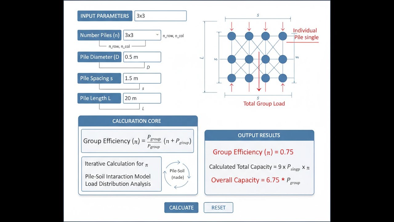
Pile Group Efficiency Interactive Visualizer
Watch how changing pile spacing and group layout shifts group efficiency and stress overlap. You can see directly how packing piles together kills capacity—the more overlap, the more you lose.
GROUP EFFICIENCY
0.67
OVERLAP INDEX
18.4°
CAPACITY LOSS
33%
FIRGELLI Automations — Interactive Engineering Calculators
Governing Equations
Here’s the main formula you’ll use to get pile group efficiency.
Converse-Labarre Formula
η = 1 - [θ / 90°] × [(m-1)n + (n-1)m + √2(m-1)(n-1)] / (mn)
Where:
- η = group efficiency factor (dimensionless, 0 to 1)
- θ = arctan(d/s) in degrees
- d = pile diameter (m)
- s = center-to-center pile spacing (m)
- m = number of rows in pile group
- n = number of columns in pile group
Group Capacity
To get group capacity, plug your calculated efficiency into this formula.
Qg = η × n × Qs
Where:
- Qg = total allowable capacity of pile group (kN)
- η = group efficiency factor
- n = total number of piles in group
- Qs = allowable capacity of single pile (kN)
Los Angeles Method
The Los Angeles method is another efficiency shortcut, best for friction piles in sands.
η = 1 / [1 + (d / (π × s)) × (n - 1)]
Application: Empirical approach for friction piles in sandy soils. Usually more conservative than Converse-Labarre at tight spacing.
Feld's Rule (Block Failure Method)
If piles are packed close in cohesive soil, Feld’s rule checks for block failure around the group.
η = Pg / (n × π × d)
Where:
- Pg = perimeter of pile group block (m)
- n = number of piles
- d = pile diameter (m)
Application: Use this for close spacing in soft clays, especially if block failure is possible. Not relevant once spacing is wide enough for each pile to work alone.
Settlement Amplification
This equation gives the ratio of group settlement to single-pile settlement.
Sg / Ss = √n × (Bg / (n × d))
Where:
- Sg = settlement of pile group (mm)
- Ss = settlement of single pile under same load per pile (mm)
- Bg = width of pile group (m)
- n = number of piles
- d = pile diameter (m)
Theory & Engineering Applications
Fundamentals of Pile Group Behavior
When you put piles in a group, the stress zones around them overlap, changing the way load transfers into the soil compared to a single isolated pile. As a result, the total capacity of a group is always less than the sum of the individuals. The group efficiency factor, η, accounts for this—expect a typical range between 0.5 and 0.9, depending on how tight the piles are, the soil, and how they're installed. In sandy soils with friction piles, efficiency drops off more slowly as you pack piles together. For cohesive soils or end-bearing systems, group effects can kick in abruptly when you drop below certain spacings, sometimes causing the group to fail along its perimeter instead of at the pile tips.
These stress overlaps aren’t just shallow. In clays, you might see soil influence zones extending 1.5 to 2 times the width of the group below the pile tips. Sandy soils tend to have a smaller but still significant influence—around 1 to 1.5 times the group width. All this means group settlement can be far greater than you’d expect from just scaling up single pile performance—settlement amplification ratios of 3 to 5 aren’t unusual for big groups in soft soils.
The Converse-Labarre Formula: Development and Limitations
The Converse-Labarre formula is the standard for group efficiency. It's straightforward and works well in many practical cases, but it's built on some rough assumptions. The arctan(d/s) term reflects how spacing and pile diameter interact, while the other terms factor in the group layout (rows, columns, diagonals).
The main catch: Converse-Labarre assumes the soil is uniform and pile-soil behavior is linear. In layered soils, or when piles are installed in a non-uniform sequence, actual efficiency often drifts 15–25% from what the formula gives. The order you drive the piles (center to edge or vice versa) changes how the soil responds—something the formula ignores. With large groups, the difference between central and edge piles gets bigger, and the formula doesn't handle perimeter effects very well. Don’t expect pinpoint accuracy if your site conditions are variable or your group is 25+ piles.
Alternative Efficiency Methods and Their Applications
Los Angeles method is a shortcut—good for a first pass on friction piles in sandy soils. It comes from test results on real jobs in California—the main tradeoff is it ignores group shape and some detailed effects, so it’s a conservative check but may leave money on the table for rectangular or odd-shaped groups. Don’t use it for end-bearing piles or piles in soft clay; it can be unconservative by quite a bit in those situations.
Feld’s rule is about perimeter block failure. When piles are closer than about 2.5 diameters in a clay, the group can act together as a big block. Here, the critical thing is shear along the group’s outside, not at the individual piles. If the spacing goes wider, Feld’s formula becomes moot—then group action fades and pile-by-pile behavior rules again. Only use it where block failure could realistically occur (typically soft clay, close spacing).
Settlement Considerations in Pile Group Design
Group settlement can catch you off guard. It’s common for a single pile to show a small amount of settlement—say, 10–15 mm—but a 3×3 group of the same piles under the same per-pile load might settle twice or three times as much. This is because the stress bulb under the group is bigger and deeper, pulling in extra settlement from compressible soils far beneath the tips. In profiles with thick soft layers, you may see group settlements a lot higher than what the formula suggests.
The settlement ratio Sg/Ss is a simple way to estimate this effect, but you still have to use your head: if soft or organic soils are hiding at depth, you’ll often get more settlement than any basic formula predicts. For anything critical, a hand calc with equivalent raft width plus real consolidation parameters—or a quick-and-dirty 3D FE model—will give you more honest numbers than the rule-of-thumb multipliers.
Simple Example
A 4×4 pile group (16 piles), 400 mm diameter, at 1.6 m spacing, each pile rated at 380 kN:
- θ = arctan(0.4 / 1.6) = 14.04°
- Converse-Labarre η = 0.642
- Group capacity = 0.642 × 16 × 380 = 3,903 kN
- Settlement ratio = 4 × (4.8 / 6.4) = 3.0 — check serviceability separately
Worked Example: Industrial Warehouse Foundation Design
Let’s walk through a warehouse column footing design. Assume a 3,200 kN column load, spacing at 9 m, and site exploration shows 8.5 m of silty sand over till. Each pile is 400 mm square, capacity 380 kN. The job: size a pile group below one column.
Step 1: Estimate Number of Piles
Assume η = 0.70 (sandy soils): n = 3,200 kN / (380 × 0.70) ≈ 12 piles. Start there.
Step 2: Pick a Layout
Try 3×4 (12 piles): good coverage and symmetry. Spacing: s = 1.4 m (about 3.5 diameters—within the 3 to 6d optimal range).
Step 3: Calculate Efficiency (Converse-Labarre)
θ = arctan(0.4/1.4) = 15.95°
Interaction term = [(3-1)×4 + (4-1)×3 + √2(3-1)(4-1)] / (3×4) = 2.124
η = 1 - (15.95/90) × 2.124 = 0.624
Step 4: Check Group Capacity
Qg = 0.624 × 12 × 380 = 2,845 kN. That’s not enough—need to revise.
Step 5: Up the Group Size
Try 4×4 (16 piles), same spacing.
Interaction term = 2.296, η = 0.593
Qg = 0.593 × 16 × 380 = 3,603 kN. You get a 12.6% buffer.
Step 6: Estimate Settlement
Bg = 3 × 1.4 = 4.2 m
Settlement ratio = 4 × (4.2 / 6.4) = 2.62
If single pile test = 12 mm, group settlement ≈ 31 mm. That’s more than the typical 25 mm limit—could be an issue.
Step 7: Optimize Spacing
Bump spacing to 1.6 m (4 diameters):
θ = arctan(0.4/1.6) = 14.04°
η = 0.642
Qg = 0.642 × 16 × 380 = 3,904 kN.
Bg = 4.8 m.
Settlement ratio = 4 × (4.8/6.4) = 3.0
Group settlement ≈ 36 mm (still a bit high for some jobs).
Summary: Final scheme: 16 piles (4×4) at 1.6 m. Capacity is fine, but settlement still pushes limits—so consider preloading, pile layout tweaks, or allow extra movement and design for it above. Tuning spacing, sequence, or even accepting a higher settlement can bring balance between cost and performance. Don’t automatically trust the first computed value—iterate and check both capacity and settlement in parallel.
Design Standards and Factor of Safety Considerations
Codes handle group reduction and safety factors in different ways. Eurocode 7 bases calculations on characteristic capacity and partial factors; ASCE 7 has stuck with global safety factors but is moving toward LRFD. Apply the group efficiency to the individual ultimate pile capacities before applying your factors of safety. Don’t double-dip by applying η to already factored numbers. For major projects, group load tests (with 2-3 test piles at real spacing) are a much more solid foundation for your design than basic theory—especially if you’re building hundreds of piles or the soil is inconsistent.
Don’t get tripped up by which numbers you’re reducing—apply efficiency first, then safety, not the other way around. Real group testing is the only way to truly remove doubt on big or unusual jobs.
Installation Effects and Construction Considerations
How you build the pile group matters—a lot. Displacement piles in sand (steel pipe, precast) densify the ground as you go, especially if you drive from the center outward. This can actually raise your efficiency compared to what the formulas predict, sometimes by 10–20%. But in soft clay, perimeter-inward is safer; otherwise, central piles can remold the clay and reduce its strength badly if you don’t leave enough delay between installations.
Bored piles are another animal—no compaction benefit, and sometimes side friction goes down if you get smear or drilling fluid infiltration. For these, use 85–90% of the calculated efficiency unless you have site tests to prove better. The pick between driven and bored piles isn’t just about calculations; you also need to weigh up cost, disturbance, access, and settlement criteria. The methods on this page give you a sound place to start—but always plug in the specific site and contractor realities before you finish your design. More situations and calculator links are collected here.
Practical Applications
Scenario: Bridge Pier Foundation in Riverbed Alluvium
Marcus has to support a highway bridge pier in 14 meters of sand with high water. Each pier takes 8,500 kN. The usual driven steel pipe piles (500 mm) test at 620 kN for a single pile. With a 4×4 group at 2 m spacing (4d), Converse-Labarre gives 0.68 efficiency and 6,733 kN capacity—not enough. Stepping up to a 6×4 arrangement and 24 piles, efficiency drops to 0.623, but total capacity jumps to 9,549 kN—now in the clear. However, the settlement ratio comes in high (3.8)—so he specifies high-modulus sand around the pile cap to limit long-term movement. In bridge work, both margin and settlement need to line up, and calculators are no replacement for a sanity check with the real soil modulus and group dimensions.
Scenario: Residential Tower Foundation Optimization
Jennifer needs foundations for a 22-story tower on soft coastal clay with a strict 40 mm settlement limit. Each column takes 2,100 kN. 350 mm precast piles have 285 kN each by test. At first glance, 9-pile groups (3×3 at 1.4 m) give just 1,820 kN; not enough. Instead of adding piles, she checks if wider spacing helps: 1.8 m (5.14d) spacing boosts efficiency, raising the 9-pile group to just under 2,000 kN. Using 12 piles at 1.6 m does the job with margin—and saves about 108 piles across the site. Here, playing with both pile count and spacing made a material difference to cost and site logistics.
Scenario: Retrofitting Existing Structure with Additional Piles
David, tasked with upgrading an old warehouse, finds the column loads will more than double. The original footings have 2×2 groups (300 mm piles at 1.2 m) and can’t be replaced. By adding 4 more piles around the perimeter, he gets a 4×4 group—mixed spacing, averaging 1.05 m (3.5d). Using Converse-Labarre, efficiency is 0.58, but this might be overly low as the soil is already compacted. Los Angeles method, more empirical for existing sites, gives 0.63. After checking his numbers and derating pile capacity for age, the group is still not quite there, but with added grade beams to redistribute the load, it’s a workable—and much cheaper—solution. With existing structures, hybrid approaches and a cautious blend of formulas often give you workable results that straight theory won’t.
Frequently Asked Questions
Why does pile group efficiency decrease as spacing decreases? +
Should I use the same efficiency formula for both friction and end-bearing piles? +
How do I account for piles in different soil layers when calculating efficiency? +
What is the relationship between group efficiency and settlement amplification? +
When should I use Converse-Labarre versus Los Angeles versus Feld methods? +
How does pile installation method affect group efficiency calculations? +
Free Engineering Calculators
Explore our complete library of free engineering and physics calculators.
Browse All Calculators →🔗 Explore More Free Engineering Calculators
About the Author
Robbie Dickson — Chief Engineer & Founder, FIRGELLI Automations
Robbie Dickson brings over two decades of engineering expertise to FIRGELLI Automations. With a distinguished career at Rolls-Royce, BMW, and Ford, he has deep expertise in mechanical systems, actuator technology, and precision engineering.
Need to implement these calculations?
Explore the precision-engineered motion control solutions used by top engineers.


