If you're working on a dam, a submarine, or just picking out a hydraulic cylinder, it all starts with knowing the pressure the fluid actually puts on whatever's submerged. The Hydrostatic Pressure Interactive Calculator is a quick way to get numbers like pressure at a certain depth, depth from known pressure, fluid density, surface force, gauge pressure, or absolute pressure—just feed in fluid density, depth, gravity, and surface area. This is one of those fundamentals that, if you get it wrong, leads to obvious and sometimes costly failures. Tanks split, seals blow, welds fail. Below you’ll find the core formulas, a step-by-step example for a sub, the background physics, and answers to edge-case questions that crop up in real design work.
What is hydrostatic pressure?
Hydrostatic pressure is the load a stationary fluid puts on something below its surface. It’s a function of depth—deeper means more weight, directly.
Simple Explanation
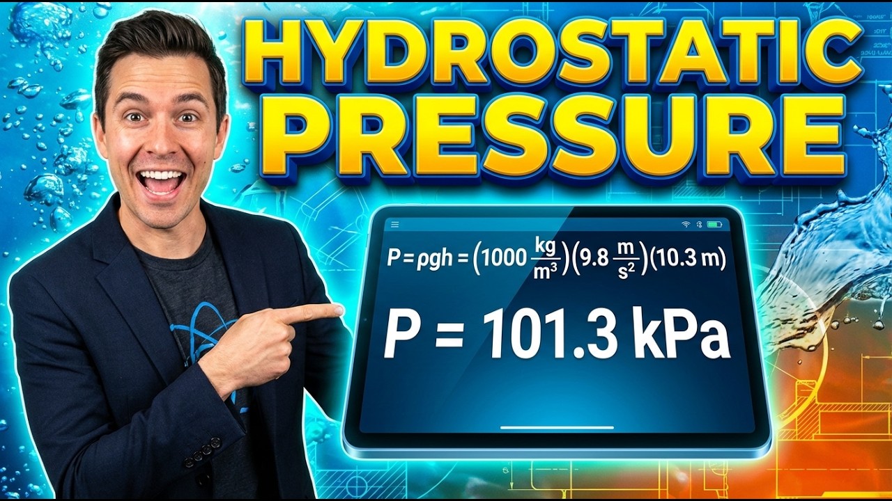
Imagine stacking blankets—each one adds weight below. Every extra meter of fluid adds more weight, so the deeper you go, the higher the pressure. A 10 m tall water column increases pressure by about 98,100 Pa, or roughly 1 atmosphere, right at the base.
📐 Browse all 1000+ Interactive Calculators
System Diagram

How to Use This Calculator
- Pick the type of calculation you need—pressure, depth, fluid density, surface force, gauge, or absolute pressure—from the dropdown.
- Input your known values. Fill in what's asked: depth (m), density (kg/m³), gravity (m/s²), atmospheric pressure (Pa), area (m²), or gauge pressure (Pa), depending on your selection.
- Double-check gravity. Unless you're working off-Earth or specifying for a test rig, 9.81 m/s² is standard. Adjust only if needed.
- Hit Calculate to get your answer.
Interactive Hydrostatic Pressure Calculator
This calculator is intended for education, concept evaluation, and preliminary design. Results are based on the equations and assumptions described on this page, but cannot account for every real-world load case, tolerance, material property, environmental condition, installation detail, safety factor, code, or regulatory requirement. Verify all inputs, assumptions, units, and results independently before selecting components or using the result in a real application. Safety-critical, structural, medical, lifting, transportation, or regulated applications must be reviewed by a qualified engineer.
📹 Video Walkthrough — How to Use This Calculator
Hydrostatic Pressure Interactive Visualizer
Watch how pressure increases linearly with depth in a fluid column. Adjust depth and fluid density to see real-time pressure calculations and force distribution on submerged surfaces.
GAUGE PRESSURE
147.2 kPa
ABSOLUTE PRESSURE
248.5 kPa
TOTAL FORCE
588.6 kN
FIRGELLI Automations — Interactive Engineering Calculators
Governing Equations
Here's the main equation for hydrostatic pressure at a given depth:
Fundamental Hydrostatic Pressure Equation
Where:
- P = Absolute pressure at depth (Pa)
- Patm = Atmospheric pressure at surface (Pa, typically 101,325 Pa at sea level)
- ρ = Fluid density (kg/m³)
- g = Gravitational acceleration (m/s², typically 9.81 m/s²)
- h = Depth below free surface (m)
Gauge Pressure
Gauge pressure is simply the portion added by the fluid column—it’s measured above atmospheric.
Force on a Submerged Surface
Where:
- F = Force on the surface (N)
- A = Surface area (m²)
This gives force at the centroid depth for flat surfaces. If you’re looking at an angled or vertical wall, you’ll need to run an integral to get the real pressure and its center across that surface.
Pressure Head
Pressure head converts pressure into the equivalent height of a specific fluid. This is handy when comparing levels or pressures in tank and piping design.
Simple Example
Water tank example: depth = 10 m, density = 1000 kg/m³, g = 9.81 m/s², atmospheric pressure = 101,325 Pa.
- Gauge pressure: 1000 × 9.81 × 10 = 98,100 Pa
- Absolute pressure: 101,325 + 98,100 = 199,425 Pa
- In bar: 199,425 / 100,000 = 1.9943 bar
Theory & Practical Applications
Fundamental Physics of Hydrostatic Pressure
Hydrostatic pressure comes from the vertical weight of the fluid above the point you’re looking at. In practice, once a fluid is at rest, depth, density, and gravity are what set the value. Pressure at a point in a fluid at rest acts the same in all directions (isotropic)—explained by Pascal’s Law. That concept shows up in all sorts of hydraulic and pneumatic systems.
Bear in mind, this linear pressure-depth relationship assumes both the density and gravity stay roughly constant and the fluid isn’t compressing. In ocean work, at extreme depths, seawater gets about 0.45% denser for every 1000 m you go down, so you’ll need to correct for that if you’re beyond 3000 m. In deep wells (>5 km), both temperature and gravity shift slightly (g drops about 0.3% for every 10 km, direction depends if you’re going up or down), and density can’t be treated as a fixed value.
Absolute vs. Gauge Pressure in Engineering Practice
If you’re specifying components or looking at phase changes and vacuum, know whether you need absolute or gauge pressure—they’re not interchangeable. Gauge pressure (ρgh) is what you get from most mechanical gauges, as they measure relative to local air. But processes with steam, condensation, evacuation, or cavitation are dependent on absolute pressure. Example: when evaluating pump cavitation, if absolute pressure goes below the vapor pressure for your process temperature, you will get vapor bubbles, regardless of the gauge reading. So a gauge reading of -50 kPa means absolute pressure is 51.3 kPa if standard atmosphere is 101.3 kPa, which could readily drop below vapor pressure for hot water at 50°C, causing trouble in a real pump system.
Fluid Property Variations and Their Impact
Fluid density changes with temperature and concentration. Water is most dense at 4°C (1000 kg/m³), and density drops to about 958 kg/m³ at boiling. Sea water density stays about 1020-1030 kg/m³, depending on salt and temperature. Crude oil spans 750–950 kg/m³. For storage tanks, use the highest bona fide density you’ll ever see in operation—often that means add a few percent for margin. For cryogenic fluids like LNG (423 kg/m³ at -162°C), you can get density stratification right in the tank, and mixing layers (rollover) create big pressure surges. So check if you have uniform conditions or if you need a more detailed density profile, especially for hazardous storage.
Industrial Applications Across Sectors
Dams: Hydrostatic pressure from the water is the dominant load. At the base of a 100-meter-high dam, you get nearly 10 bar of gauge pressure. The total force acts 1/3 of the way up—for example, 33 m from the base—with a triangular profile. Uplift reduction features like drains are there to reduce these loads at the foundation.
Subsea: A pressure vessel at 3000 m depth is dealing with roughly 300 bar (30 MPa) external. Wall openings are stress risers, and the “crush” depth is calculated with a good buffer (1.5x–2x rating). It’s not just about pressure—the structure also needs to be checked for buckling, not just yielding.
Hydraulic systems: Hydrostatic pressure is what gives you force amplification (small piston pushes big piston using fluid). But watch out for where your reservoir sits—if it’s above your actuator, you’re getting extra “static head” whether you want it or not, and fittings need to be rated for local pressures, not just dynamic ones.
Geotechnical: Pore pressure in soil follows the same physics. For stability, it’s the effective stress you care about, not just the total. If you drop the water table suddenly or don’t account for hydrostatic gradients, you can lose soil strength, and excavation support can fail. Always know your baseline pore pressure, not just what’s in some table.
Worked Example: Submarine Pressure Hull Design Check
Problem Statement: A research submarine is rated for 2400 meters in seawater. Pressure hull: outside diameter 2.8 m, 38 mm wall thickness, HY-100 steel (690 MPa yield). Find: (a) hydrostatic external pressure, (b) resulting hoop stress, (c) safety factor, (d) effect if swapped to a fresh water lake.
Given:
- Depth: h = 2400 m
- Seawater density: ρ = 1025 kg/m³
- Fresh water: ρ = 1000 kg/m³
- g = 9.81 m/s²
- Do = 2.8 m; wall = 0.038 m
- Yield: 690 MPa
(a) External gauge pressure at 2400 m (seawater):
Pgauge = (1025 kg/m³)(9.81 m/s²)(2400 m) ≈ 24.124 MPa (241.24 bar)
This is the external load all over the hull.
(b) Hoop stress:
For a thin-walled cylinder: σhoop = P × r / t
Mean radius: r = (2.8 - 0.038)/2 = 1.381 m
So: σhoop = (24.124 MPa × 1.381 m) / 0.038 m ≈ 876.4 MPa
This is above the steel’s yield. This shows why deep sub hulls need thick walls or reinforcement. In reality, thick-wall (Lame) equations are used and ring stiffeners are added.
For thick wall, calculate:
Inner diameter: 2.8 - 0.076 = 2.724 m; outer r = 1.4 m; inner r = 1.362 m
Max hoop stress: σhoop,max = -P × (ro² + ri²) / (ro² - ri²) = about -875.3 MPa
Again, this is over the 690 MPa steel limit, so design is not adequate.
(c) Safety factor:
SF = 690 / 875.3 ≈ 0.79 (bad—should be well over 1.0)
Hull must be thicker, or you need structural rings much closer together. Usually, wall thickness gets pushed above 60 mm at these depths.
(d) If used in fresh water:
P = (1000)(9.81)(2400) = 23.544 MPa
ΔP = 24.124 - 23.544 = 0.580 MPa (2.4% less pressure)
If a sub is safe in the ocean at 2400 m, it can go a bit deeper in fresh water, but you should recalculate for other loads and temperature effects.
Non-Newtonian Fluids and Complex Geometries
The simple P = ρgh equation is based on Newtonian (regular, simple) fluids. If you’re dealing with stuff like drilling mud or slurries, density still runs the hydrostatic equation, but actual pressure drop with flow gets a lot more complicated. Drilling mud (like bentonite at 1180 kg/m³) gives a higher hydrostatic column, so you get better well control than with water alone.
For more fluid calculations, see the engineering calculator library—there are tools for flow, head loss, Bernoulli, and so on that fit alongside hydrostatics.
Frequently Asked Questions
Free Engineering Calculators
Explore our complete library of free engineering and physics calculators.
Browse All Calculators →🔗 Explore More Free Engineering Calculators
- Duct Sizing Calculator — Velocity Pressure
- CFM Calculator — Room Ventilation Airflow
- Reynolds Number Calculator — Laminar or Turbulent
- Bernoulli Equation Calculator
- Mean Free Path Calculator
- Hydraulic Conductivity Calculator
- Prandtl Number Calculator
- Velocity Jacobian Matrix Calculator
- Force-Torque Sensor Resolution Checker
- Coriolis Force on Rotating Links Calculator
About the Author
Robbie Dickson — Chief Engineer & Founder, FIRGELLI Automations
Robbie Dickson brings over two decades of engineering expertise to FIRGELLI Automations. With a distinguished career at Rolls-Royce, BMW, and Ford, he has deep expertise in mechanical systems, actuator technology, and precision engineering.
Need to implement these calculations?
Explore the precision-engineered motion control solutions used by top engineers.


