If you don’t get the relationship between intensity, flux, and surface illuminance right, your lighting plan either wastes power or leaves areas under-lit. This calculator lets you go from lux to candela to lumens (and back) with the right input: distance, solid angle, area, and lighting angle. That comes up in a lot of real-world jobs: architectural lighting, vision systems, photography, factory work—anywhere the light level can make or break function or safety. You’ll find the essential equations, a step-by-step gallery example, practical design notes, and a FAQ covering where these calculations usually go wrong.
What is photometric conversion?
Photometric conversion is about working out how light intensity (candela), total light (lumens), and surface illuminance (lux) affect one another. Each describes a different, but connected, piece of what’s coming out of a light source. If you know any one of them along with the basic physical setup—distance, area, direction—you can solve for the others.
Simple Explanation
Picture lumens as the total water spilling out of a hose, candela as how forcefully that water hits a single point, and lux as how much water ends up per square meter on the ground. A tight nozzle doesn’t give you more water, but it sure makes a smaller patch wetter—same principle in lighting. Narrow the beam, you get higher lux and candela, lumens don’t change. Widen the beam, less light per area even though the lamp output is the same.
📐 Browse all 1000+ Interactive Calculators
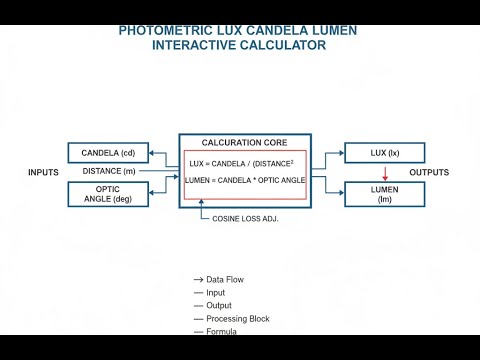
Photometric Quantities Diagram

How to Use This Calculator
- Pick the calculation mode—what do you need to solve for? (lux, candela, lumens, or distance)
- Fill in the knowns for your part: intensity, area, solid angle, whatever is illuminated
- Set the incidence angle to zero unless your beam is coming in off-perpendicular (use degrees off-normal if it is)
- Click Calculate. That’s it.
Photometric Interactive Calculator
This calculator is intended for education, concept evaluation, and preliminary design. Results are based on the equations and assumptions described on this page, but cannot account for every real-world load case, tolerance, material property, environmental condition, installation detail, safety factor, code, or regulatory requirement. Verify all inputs, assumptions, units, and results independently before selecting components or using the result in a real application. Safety-critical, structural, medical, lifting, transportation, or regulated applications must be reviewed by a qualified engineer.
Photometric Lux Candela Lumen Interactive Visualizer
Watch how luminous intensity (candela), surface illuminance (lux), and distance interact through the inverse square law. Adjust parameters to see real-time photometric calculations with visual beam patterns and illumination zones.
ILLUMINANCE
56 lux
TOTAL LUMENS
524 lm
SOLID ANGLE
1.05 sr
FIRGELLI Automations — Interactive Engineering Calculators
Equations & Formulas
Here’s how to get illuminance from a point source at a known distance and angle:
Inverse Square Law (Point Source Illuminance)
E = (I × cos θ) / d²
E = Illuminance (lux or lm/m²)
I = Luminous intensity (candela, cd)
θ = Angle of incidence (degrees or radians)
d = Distance from source (meters)
This one calculates total lumens from a known intensity and beam angle:
Luminous Flux from Intensity
Φ = I × Ω
Φ = Luminous flux (lumens, lm)
I = Luminous intensity (candela, cd)
Ω = Solid angle (steradians, sr)
For a full sphere: Ω = 4π ≈ 12.566 sr
This gives average illuminance from flux and area:
Average Illuminance from Flux
Eavg = Φ / A
Eavg = Average illuminance (lux)
Φ = Total luminous flux (lumens)
A = Surface area (square meters)
Assumes uniform flux distribution over the surface
Calculate solid angle for a conical beam like most spotlights:
Solid Angle of a Cone
Ω = 2π(1 - cos α)
Ω = Solid angle (steradians)
α = Half-angle of cone (radians)
For small angles: Ω ≈ π(α²) when α is in radians
Get average intensity from known flux (useful with LED datasheets):
Candela from Known Flux Distribution
I = Φ / Ω
I = Average luminous intensity (candela)
Φ = Luminous flux within solid angle (lumens)
Ω = Solid angle of emission (steradians)
Valid for uniform intensity distribution within Ω
Simple Example
A 100 cd spotlight aimed straight down (0° angle) at a surface 2 meters below:
E = (100 × cos 0°) / 2² = 100 / 4 = 25 lux
If you double the distance (4 m), you get 100 / 16 = 6.25 lux. This is what the inverse square law means in day-to-day lighting jobs.
Theory & Engineering Applications
You’re not getting far in lighting design unless you can measure light in a way that relates to what people actually see. Photometry is built around that. It’s defined for what the human eye responds to—unlike radiometry, which just looks at energy regardless of whether you can see it. The V(λ) weighting means photometric calculations line up with where human vision is sensitive and why lighting choices are made around lux, not watts.
Fundamental Photometric Quantities
The candela (cd) is just the SI base unit for how much light heads out in a particular direction. Now, it’s defined using a specific wavelength at a specified intensity per solid angle—no guessing, no “standard candles.” It anchors how everything else (lux, lumens) gets worked out.
When you see “lumens” (lm), you’re talking about all the visible light emitted in every direction. For a source that points equally every way, 1 candela gives 4π lumens—basic geometry. Fixtures and LEDs aren’t perfect isotropic sources though, so you often need the manufacturer’s data or to do the math over the whole emission sphere if you want the total. Efficacy (lumens/watt) just tells you how good the lamp is at turning electricity into visible light, but it requires good input data.
Illuminance tells you how much light lands per square meter—measured in lux (or lm/m²). One lux is just 1 lumen spread out over 1 m² of surface. If you’re planning a space, this is the number that tells you if people can see what they’re doing. Check codes: 500 lux for detail work at desks, 200 lux for hallways, 50 or less for bare-minimum escape lighting. Don’t mix up luminance (how bright something looks) with illuminance (how much light hits it)—both matter, but for different calculations.
The Inverse Square Law and Distance Effects
If the light source is much smaller than the distance you’re measuring from, and the beam’s not blocked, illuminance at a surface drops off by the square of the distance. That’s E = I/d². Double the distance, you’ve got only a quarter of the light per area. Triple it, you’re down to one-ninth. This makes fixture placement and mounting height a lot more important than most people realize—move a reading lamp away and it becomes nearly useless without more power or a tighter beam.
If the light isn’t hitting straight on, the cosine comes into play. The more the beam grazes the surface, the less effective light you’re getting. At a 60 degree angle, you get half the perpendicular illuminance. It’s an easy thing to forget, but if you want even lighting on a wall or display, you need to account for how severe the angle is or you end up with bright spots and dead zones.
Solid Angles and Beam Optics
Steradians (sr) are just the three-dimensional version of regular angle measurements. Full sphere: 4π steradians. Nobody designs a light that throws equally everywhere though. Most use reflectors or lenses to focus flux into a specific region—this is what makes a spotlight a spotlight instead of just a bulb.
If you restrict a beam to a 10-degree half-angle, you’re lighting only about 0.19% of a sphere. With that, you can bump up candela by a huge factor compared to the same flux spread over a wider area. It’s why some spotlights make sharp illuminated patterns from a moderate-wattage bulb—tight beam, high intensity, same lumens, very different end result. Watch your approximations though; for small angles you can shortcut, but above about 20 degrees you need the real formula.
Real-World Complications and Limitations
When you’re close to a big light source (LED panel, tube light), the standard point-source math misses the mark. Parts of the source are at different distances and angles from the point you’re measuring—especially true if the panel is wider than the “working distance” you’re using. If the measuring spot is less than five times the source’s largest dimension away, expect errors to creep in. There are ways to model this with more complex integration or software, but in practice you often end up resorting to actual measurements or using rough correction factors.
The real surface matters too. Calculated illuminance is just what arrives; what you see (luminance) is affected by how reflective, textured, or directional the surface is. Two surfaces under identical lighting look wildly different if one’s black velvet and the other is white paint. This gets even more complicated if you’re dealing with glossy (specular) or structured finishes. Modeling these effects is possible, but you often end up measuring them directly.
Worked Example: Gallery Lighting Design
Suppose you’ve got a painting 1.2 m x 0.9 m in a gallery. The curator wants about 300 lux on it—not enough to cause fading, but plenty for clear viewing. The available spotlight can put out 2400 lumens, reflector focuses to a 30° half-angle (60° wide beam). Let’s figure out where to mount it and whether the beam covers the painting efficiently.
Step 1: Calculate the beam solid angle.
Half-angle α = 30° = 0.5236 radians
Ω = 2π(1 - cos 0.5236) = 2π(1 - 0.8660) = 2π(0.1340) = 0.8418 steradians
Step 2: Find average luminous intensity within the beam.
I = Φ / Ω = 2400 lm / 0.8418 sr = 2850.9 candela
Step 3: Work out the distance for 300 lux at beam center (perpendicular).
E = I / d²
300 = 2850.9 / d²
d² = 2850.9 / 300 = 9.503
d = 3.083 meters
Step 4: Check beam coverage at that distance.
At d = 3.083 m, the beam radius is r = d × tan(30°) = 3.083 × 0.5774 = 1.780 meters. Beam diameter is then 3.56 m, which is much wider than the 1.2 m painting—the beam covers the target and then some, but the extra spill is wasted output.
Step 5: Find illuminated area and average illuminance.
Beam area: A = πr² = π(1.780)² = 9.95 m²
Average E = 2400 lm / 9.95 m² = 241.2 lux
Step 6: Assess what this means for your design.
You want 300 lux at the painting, but only about 260 lumens are actually hitting it (1.08 m² x 241 lux), so roughly 89% of the lamp’s output is lighting the wall. If you want better efficiency, use a tighter beam or move the light closer, but be sure not to go above the safe illuminance and risk damaging the artwork. This is the sort of real-world tradeoff you find all the time: more output doesn’t always equal more on-target lighting—you have to look at distance and angle as well. Photometric calculations help, but sometimes you’ll need iterative measurements or software to get the results dialed in.
Applications Across Industries
For building lighting, photometry is the backbone of making sure the numbers line up with code and what users need. IES targets are practical: 750 lux for surgical, 300–500 for offices, lower for lobbies. Lighting designers match these up with fixture data, lay out placements, and estimate uniformity. Sunlight and windows further complicate things, so combining photometry with solar calculations helps fine-tune solutions and save power.
Machine vision in factories is about controlling not just brightness but uniformity and angle. Defect inspection needs shadowless, even lighting—usually specified as percent uniformity across the field of view. For dimensional checks, it’s often about structuring light for good edge contrast. All of this is more about engineering light onto the target than maximizing total lumens.
Photography and film lighting is less about code and more about consistency and flexibility. Photographers use lux meters to set up scene exposure and balance light ratios. Moving a light just a meter further or closer can make a drastic difference—a reality that’s easier to manage when you know the inverse-square math cold. This matters when you’ve got to match shots from different days or locations.
To explore other technical calculators (from optics to fluid mechanics), check out FIRGELLI Engineering Calculators.
Practical Applications
Scenario: Warehouse Safety Compliance Verification
Marcus is checking if his warehouse lighting meets the 50-lux OSHA minimum in aisles and 200 lux for packing. Switched to 15,000-lumen LED bays, 8 meters up. Using this calculator in “lux from candela & distance” mode, he divides the 15,000 lm by beam solid angle (2.8 sr; check the spec sheet) to get 5,357 candela. At 8 m, the direct illuminance is 5,357/64 = 83.7 lux. Testing spot checks between fixtures, with longer path and more angled incidence, he finds a low of 62 lux at the midpoints—still enough margin, but corners need a supplemental light to cover all legal zones. This saves the cost of over-lighting the whole grid.
Scenario: Photography Studio Lighting Setup
Diana needs an even 800 lux on a 1.5 x 1.5 m product table—color work, needs consistency. Her LED panel puts out 8,500 lm, 40° half-angle. Using the calculator, she divides 8,500 lm by the calculated solid angle (1.957 sr) to get 4,343 cd. Solving for distance: sqrt(4,343/800) = 2.33 m to hit 800 lux at the table center. Checks with a lux meter; at corners (off-axis), the reading drops to 520 lux due to angle. She adds two fill lights at 45°, each giving 280 lux at the corners, pulling total up to spec with good uniformity. That’s faster than power-guessing or trial and error.
Scenario: Stadium Lighting Specification Review
Carlos is checking a vendor claim: 32 x 50,000-lumen floodlights at 25m on a soccer field should yield 500 lux for TV. Total lm is 1,600,000; the field is 7,140 m². 1,600,000 / 7,140 = 224 lux if every lumen lands on target, which isn’t realistic. The proposal falls short before you even dig into losses or beam coefficients. He demands real photometric files, and after running those, finds either more fixtures or tighter beams are needed to get real 500-lux average. Running the numbers quickly steers clear of costly mistakes and rework.
Frequently Asked Questions
Free Engineering Calculators
Explore our complete library of free engineering and physics calculators.
Browse All Calculators →🔗 Explore More Free Engineering Calculators
About the Author
Robbie Dickson — Chief Engineer & Founder, FIRGELLI Automations
Robbie Dickson brings over two decades of engineering expertise to FIRGELLI Automations. With a distinguished career at Rolls-Royce, BMW, and Ford, he has deep expertise in mechanical systems, actuator technology, and precision engineering.
Video Walkthrough - How to Use This Calculator
Need to implement these calculations?
Explore the precision-engineered motion control solutions used by top engineers.


