When you need to turn rotary motion into smooth, repeatable linear motion, and care about knowing position, velocity, and acceleration at every crank angle, a Scotch yoke is one of the simpler approaches. The calculator below gives you position, velocity, and acceleration for a Scotch yoke using crank radius, RPM, and crank angle. Getting these numbers matters in anything from engines to reciprocating compressors, or whenever you're building for a true sinusoidal motion path. Below you'll find the equations, a worked example, notes on mechanism behavior, and a FAQ.
What is a Scotch Yoke Mechanism?
A Scotch yoke mechanism takes steady rotary motion and drives a slot in a straight path, producing linear back-and-forth movement that tracks a sine wave. You can predict linear position, velocity, and acceleration at every crank angle with basic math, which makes it easy to design for controlled motion.
Simple Explanation
Picture a pin fixed to a spinning disk, sliding inside a straight slot. As the disk turns, that pin forces the slot (and anything attached) to move in and out along a line. Speed is highest at mid-stroke and drops to zero near each end, matching a smooth sine wave. That’s why it’s handy for any job needing repeatable, predictable motion.
📐 Browse all 1000+ Interactive Calculators
Scotch Yoke Mechanism Diagram

Scotch Yoke Mechanism Calculator
How to Use This Calculator
This calculator is intended for education, concept evaluation, and preliminary design. Results are based on the equations and assumptions described on this page, but cannot account for every real-world load case, tolerance, material property, environmental condition, installation detail, safety factor, code, or regulatory requirement. Verify all inputs, assumptions, units, and results independently before selecting components or using the result in a real application. Safety-critical, structural, medical, lifting, transportation, or regulated applications must be reviewed by a qualified engineer.
- Enter the crank radius (r) in mm or inches — this is the distance from the center of rotation to the crank pin.
- Enter the RPM — the rotational speed of the crank in revolutions per minute.
- Enter the crank angle (θ) in degrees — the angular position you want to analyze.
- Click Calculate to see your result.
Scotch Yoke Mechanism Interactive Visualizer
Visualize how rotational motion converts to perfect sinusoidal linear motion in real-time. Adjust crank radius, RPM, and angle to see instant position, velocity, and acceleration calculations with animated mechanism movement.
POSITION
0.0 mm
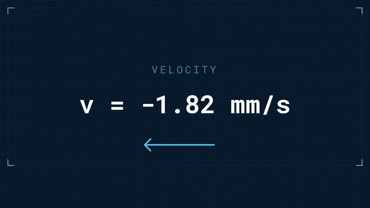
VELOCITY
0 mm/s
ACCELERATION
0 mm/s²
FIRGELLI Automations — Interactive Engineering Calculators
Mathematical Equations
Use the formula below to calculate scotch yoke position, velocity, and acceleration.
The scotch yoke mechanism calculator uses the following fundamental equations to determine motion characteristics:
Position Equation:
x = r cos(ωt)
Velocity Equation:
v = -rω sin(ωt)
Acceleration Equation:
a = -rω² cos(ωt)
Where:
- x = Linear position of the yoke
- r = Crank radius
- ω = Angular velocity (rad/s)
- t = Time (or θ/ω for specific angle)
- v = Linear velocity
- a = Linear acceleration
Simple Example
Crank radius: 50 mm | RPM: 600 | Angle: 90°
ω = (600 × 2π) / 60 = 62.83 rad/s
Position: x = 50 × cos(90°) = 0 mm
Velocity: v = −50 × 62.83 × sin(90°) = −3,141 mm/s
Acceleration: a = −50 × 62.83² × cos(90°) = 0 mm/s²
How Scotch Yoke Mechanisms Work
Scotch yokes take rotary input and turn it into pure sinusoidal linear motion using a straightforward setup. The calculator on this page is aimed at letting you analyze that motion with simple inputs.
The main components are a crank (with a pin) rotating at constant speed, and a straight slot that the pin slides inside. The pin traces a circle, while the slot follows a line. The system relies on geometry, not fancy linkages: as the crank rotates, the pin sets the slot's position according to the cosine of the crank angle.
The real reason to use a Scotch yoke is that the output position is truly sinusoidal and straightforward to calculate. This minimizes surprises in design and analysis.
Motion Characteristics
This type of mechanism gives you predictable results if you pay attention to a few details:
Position Profile: Linear position maps right to a cosine wave—max displacement at crank horizontal, zero at vertical. This guarantees no sudden stops or changes in direction, which is good for system reliability.
Velocity Profile: Velocity tracks a negative sine curve: it peaks when the yoke is mid-stroke, zeros at the extremes. That helps avoid shock loading.
Acceleration Profile: Acceleration follows a negative cosine, peaking at the motion extremes, and passing through zero at mid-stroke. Be aware, this is where your highest forces show up, which drives sizing for mechanical strength.
Practical Applications
Scotch yoke mechanisms show up in applications where predictable, sinusoidal motion is needed—not just for tradition, but for function. Here’s where you’ll see them:
Engine Applications
A few engine designs (usually alternatives to conventional crank/connecting-rod) rely on Scotch yokes for the main piston motion. They reduce side loads and can lower vibration, which is a main advantage. You’ll see them sometimes in aircraft and other places where vibration matters.
Compressor Systems
Reciprocating compressors benefit from the controlled timing a Scotch yoke provides, which allows for repeatable compression cycles and synchronizes well with valve timing. When used in compressors, this predictability improves system efficiency and life.
Linear Actuator Integration
Automation setups sometimes mix Scotch yokes with FIRGELLI linear actuators when both sinusoidal and programmable motion are needed. This gives you reliable, calculated stroke profiles right out of the math, and is useful for robotics or special manufacturing tasks.
Worked Example
Let’s run the math for a specific case:
- Crank radius (r): 75 mm
- Operating speed: 1200 RPM
- Analysis angle: 60 degrees
Step 1: Convert RPM to angular velocity
ω = (1200 × 2π) / 60 = 125.66 rad/s
Step 2: Calculate position
x = 75 × cos(60°) = 75 × 0.5 = 37.5 mm
Step 3: Calculate velocity
v = -75 × 125.66 × sin(60°) = -75 × 125.66 × 0.866 = -8,161 mm/s
Step 4: Calculate acceleration
a = -75 × (125.66)² × cos(60°) = -75 × 15,791 × 0.5 = -593,412 mm/s²
This shows that for moderate crank radius and high RPM, you can reach high velocities and accelerations quickly. This underlines the importance of checking your load and selecting the right materials and dimensions.
Design Considerations
Material Selection
The pin needs to slide against the slot without excess wear. Most designs use hardened steel pins and bronze or steel yokes. You can get away with simple materials at low speed, but as speeds and forces rise, don't ignore proper hardness and surface finish, and always expect some maintenance.
Clearance and Tolerances
The gap between pin and slot needs to be enough that things don’t jam or seize, but not so large that you get slop or chatter. Too much clearance leads to backlash and inaccuracy; too little and you risk high wear or early failure. Use this calculator for your kinematics, but check actual bearing fits for your load and life requirements.
Load Analysis
Peak loads happen at stroke ends—this is determined by acceleration, not just speed. Always check loads at every crank position, and don’t underestimate fatigue when cycling under high loads.
Lubrication Systems
Sliding surface needs frequent lubrication, especially at higher speeds. If you skip or underspec your lubrication, expect fast wear. Grease or oiling—choose according to speed and cycle frequency.
Vibration and Noise Control
While Scotch yokes usually vibrate less than crank-slider setups, nothing’s perfect at high RPM. Unbalanced forces and impacts (especially with too much clearance) can still create noise and shaking, so design mounting and balance accordingly.
Integration with Modern Control Systems
These days, it’s common to pair a Scotch yoke with a programmable actuator or sensor for feedback. It moves the system beyond pure trigonometric sinusoidal motion, making control easier and more flexible—especially with FIRGELLI linear actuators or other position-driven hardware.
For mechanism sizing, cycling, or comparing with other types of motion, look up the engineering calculator library which covers other mechanical motion systems.
Frequently Asked Questions
📐 Browse all 1000+ Interactive Calculators →
About the Author
Robbie Dickson
Chief Engineer & Founder, FIRGELLI Automations
Robbie Dickson brings over two decades of engineering expertise to FIRGELLI Automations. With a distinguished career at Rolls-Royce, BMW, and Ford, he has deep expertise in mechanical systems, actuator technology, and precision engineering.
📹 Video Walkthrough — How to Use This Calculator
📹 Video Walkthrough — How to Use This Calculator
Need to implement these calculations?
Explore the precision-engineered motion control solutions used by top engineers.


