Choosing the wrong RC values for a timing or filter circuit means your design either misses its delay target, passes the wrong frequencies, or oscillates when it shouldn't. Use this RC Circuit Interactive Calculator to calculate time constant, charging/discharging voltage, cutoff frequency, impedance, phase angle, and stored energy using resistance, capacitance, voltage, time, and frequency inputs. RC circuits show up everywhere — filter design in audio and RF systems, timing control in automotive and industrial electronics, and power supply decoupling in digital and analog boards. This page covers the core equations, a worked automotive relay example, a simple example to get you started, and a full FAQ section.
What is an RC circuit?
An RC circuit is a simple electrical circuit containing a resistor (R) and a capacitor (C). Together, these two components create a time delay when charging or discharging, and they filter out certain signal frequencies depending on the values you choose.
Simple Explanation
Think of the capacitor as a small bucket and the resistor as a narrow pipe feeding it. The narrower the pipe (higher resistance), or the bigger the bucket (higher capacitance), the longer it takes to fill or empty. That fill time is your time constant — it controls how fast your circuit responds to a voltage change.
📐 Browse all 1000+ Interactive Calculators
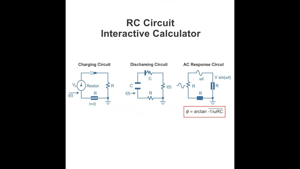
RC Circuit Diagram

How to Use This Calculator
- Select a calculation mode from the dropdown — choose from time constant, discharging voltage, cutoff frequency, impedance/phase, energy stored, or time to reach a voltage percentage.
- Enter your resistance (R) in ohms and capacitance (C) in farads. Additional fields for voltage, time, frequency, or target percentage will appear based on the mode selected.
- Fill in all visible input fields with your circuit values.
- Click Calculate to see your result.
RC Circuit Interactive Calculator
RC Circuit Interactive Visualizer
Watch how resistance and capacitance values affect charging curves, time constants, and filter response in real-time. Adjust the slider to see exponential charging behavior and frequency cutoff visualization.
TIME CONSTANT
0.10 s
CUTOFF FREQ
1.6 Hz
FINAL VOLTAGE
7.6 V
FIRGELLI Automations — Interactive Engineering Calculators
RC Circuit Equations
Simple Example
R = 10,000 Ω, C = 0.000001 F (1 µF), V₀ = 12 V, t = 0.01 s
Time constant: τ = 10,000 × 0.000001 = 0.01 s
Charging voltage at t = 0.01 s: VC = 12 × (1 − e−1) = 12 × 0.632 = 7.58 V
Cutoff frequency: fc = 1 / (2π × 0.01) ≈ 15.92 Hz
Time Constant
Use the formula below to calculate the RC time constant.
τ = R × C
where: τ = time constant (s), R = resistance (Ω), C = capacitance (F)
Charging Voltage (Capacitor)
Use the formula below to calculate charging voltage.
VC(t) = V₀ × (1 − e−t/τ)
where: VC = capacitor voltage at time t (V), V₀ = source voltage (V), e = Euler's number (≈2.718)
Discharging Voltage (Capacitor)
Use the formula below to calculate discharging voltage.
VC(t) = V₀ × e−t/τ
where: V₀ = initial capacitor voltage (V)
Charging Current
Use the formula below to calculate charging current.
i(t) = (V₀ / R) × e−t/τ
where: i = current through circuit (A)
Cutoff Frequency (Low-Pass Filter)
Use the formula below to calculate cutoff frequency.
fc = 1 / (2πτ) = 1 / (2πRC)
where: fc = cutoff frequency (Hz), π ≈ 3.14159
Capacitive Reactance (AC)
Use the formula below to calculate capacitive reactance.
XC = 1 / (ωC) = 1 / (2πfC)
where: XC = capacitive reactance (Ω), ω = angular frequency (rad/s), f = frequency (Hz)
Total Impedance (AC)
Use the formula below to calculate total AC impedance.
Z = √(R² + XC²)
where: Z = total impedance magnitude (Ω)
Phase Angle (AC)
Use the formula below to calculate phase angle.
φ = arctan(−XC / R)
where: φ = phase angle (radians or degrees), negative indicates current leads voltage
Energy Stored in Capacitor
Use the formula below to calculate energy stored in a capacitor.
E = ½ × C × V²
where: E = energy stored (J), V = voltage across capacitor (V)
Theory & Practical Applications
RC Circuit Fundamentals and Dynamic Behavior
RC circuits consist of a resistor and capacitor in series or parallel configurations, forming the basis for timing circuits, filters, and signal conditioning systems. The time constant τ = RC governs all transient behavior in these circuits. Unlike purely resistive circuits where current responds instantaneously to voltage changes, RC circuits exhibit exponential charge and discharge characteristics that create deliberate time delays or frequency-dependent responses. The critical engineering insight often overlooked in basic treatments is that the time constant represents not just a single point but defines the entire response curve: at t = τ, the capacitor reaches 63.2% of the final value during charging (1 − e−1 ≈ 0.632), and at t = 5τ, the circuit reaches 99.3% completion, which is conventionally considered "fully charged" for most practical purposes.
The physics governing RC circuit behavior stems from Kirchhoff's voltage law combined with the capacitor's defining relationship Q = CV, which when differentiated gives i = C(dV/dt). During charging, the voltage across the resistor VR = iR must equal the source voltage minus the capacitor voltage: V₀ − VC = iR. Substituting i = C(dVC/dt) yields the differential equation RC(dVC/dt) + VC = V₀, whose solution produces the exponential charging equation. The resistor initially carries maximum current when VC = 0, then current decays exponentially as the capacitor voltage approaches the source voltage and the potential difference across the resistor diminishes. This current-limiting function of the resistor is critical in preventing instantaneous high-current surges that could damage components or power supplies.
Timing Applications and Precision Considerations
RC timing circuits form the basis for oscillators, pulse generators, delay circuits, and timing control systems in applications from automotive turn signal flashers to industrial process control delays. In precision timing applications, engineers must account for component tolerances that compound in the product RC: a resistor with ±5% tolerance and a capacitor with ±10% tolerance yield a time constant uncertainty of approximately ±15% (worst case), though statistical analysis reduces this to about ±11% RMS. Temperature coefficients further affect accuracy: electrolytic capacitors exhibit capacitance changes of −2% to +20% over 0°C to 70°C, while film capacitors maintain ±1% or better. For timing accuracy better than ±5%, metal film resistors (±1%, ±50 ppm/°C) and polypropylene or polyester film capacitors should be specified.
The practical limitation in RC timing circuits stems from capacitor leakage resistance, which appears as a parallel resistance Rleak across the capacitor. Real capacitors don't hold charge indefinitely — they self-discharge through internal leakage currents. The effective time constant becomes τeff = ReqC where Req = R || Rleak = (R × Rleak)/(R + Rleak). For Rleak much greater than R, this approximates RC as expected, but as R increases (as in long-delay timers with megohm resistances), the leakage becomes significant. High-quality polypropylene capacitors achieve Rleak values exceeding 105 MΩ×µF, while aluminum electrolytics may be as low as 102 MΩ×µF, making them unsuitable for very long time delays. For delays beyond 10 minutes, CMOS timer ICs with internal counters provide superior accuracy.
Frequency Response and Filter Applications
When excited by AC signals, RC circuits function as frequency-dependent voltage dividers, forming the foundation of passive filter design. The cutoff frequency fc = 1/(2πRC) represents the −3 dB point where the output voltage falls to 70.7% of the input (1/√2), corresponding to half-power transmission. In a series RC circuit with output taken across the capacitor, low frequencies see high capacitive reactance XC = 1/(2πfC), producing large voltage drops across C, while high frequencies see low XC, effectively shorting the capacitor and dropping voltage across R instead. This creates a low-pass filter with roll-off slope of −20 dB/decade (−6 dB/octave) beyond fc.
The phase relationship between voltage and current in RC circuits introduces a critical engineering consideration for signal integrity and system stability. In a series RC circuit, the current leads the total voltage by phase angle φ = arctan(−XC/R), ranging from 0° at DC (XC → ∞, purely resistive) to −90° at very high frequencies (XC → 0, purely capacitive). At the cutoff frequency where XC = R, the phase shift is −45°. This phase shift accumulates through cascaded RC stages: a three-stage RC filter exhibits −135° phase shift at fc, which can cause instability in feedback amplifiers. The Bode plot shows both magnitude and phase response, with the phase shift beginning at approximately 0.1fc and reaching 90% of its final value by 10fc. Op-amp circuit designers must account for this phase margin when determining compensation networks to prevent oscillation.
Signal Conditioning and Practical Circuit Design
RC circuits serve as coupling capacitors to block DC while passing AC signals, and as bypass capacitors to short AC noise to ground while maintaining DC bias voltages. In audio applications, a 10 µF coupling capacitor with a 47 kΩ input impedance produces fc = 1/(2π × 47000 × 10 × 10−6) ≈ 0.34 Hz, well below the 20 Hz lower limit of human hearing, ensuring flat frequency response throughout the audio band. The capacitor value must be large enough that its reactance at the lowest frequency of interest is much smaller than the load resistance: XC < 0.1Rload provides less than 0.5% amplitude error and negligible phase shift.
Power supply decoupling represents another critical RC application where parasitic inductance in supply lines creates voltage noise from current transients. Ceramic capacitors (0.1 µF) positioned within 5 mm of IC power pins provide low-impedance paths for high-frequency switching currents, with the short lead length minimizing parasitic inductance that would otherwise compromise effectiveness above 10 MHz. Bulk electrolytic capacitors (10–100 µF) handle lower-frequency load variations. The ESR (equivalent series resistance) of the capacitor combines with its capacitance to form an RC filter — aluminum electrolytics with ESR of 0.5–2 Ω create pole frequencies in the kHz range, while ceramic capacitors with ESR below 0.1 Ω maintain effectiveness into the MHz range. For switch-mode power supplies operating at hundreds of kHz, low-ESR polymer capacitors are specified.
Worked Example: Automotive Relay Delay Circuit Design
Problem: Design an RC delay circuit for an automotive application that keeps interior lighting illuminated for 18 seconds after the door closes. The relay coil requires 85 mA at 12 V to energize (resistance 141 Ω) and drops out at currents below 50 mA. The system operates from a 14.2 V nominal vehicle electrical system with a tolerance of ±1.5 V (12.7 V to 15.7 V). Calculate: (a) appropriate R and C values, (b) actual delay times at minimum and maximum supply voltages, (c) power dissipation in the resistor, and (d) required capacitor voltage rating considering worst-case conditions.
Solution:
(a) Component Selection: We need to determine the voltage at which the relay drops out. Using Ohm's law, dropout voltage Vdropout = I × Rcoil = 0.050 A × 141 Ω = 7.05 V. The capacitor must discharge from the initial voltage to 7.05 V in 18 seconds. Using the discharge equation VC(t) = V₀ × e−t/τ, we rearrange to find τ:
7.05 = 14.2 × e−18/τ
0.497 = e−18/τ
ln(0.497) = −18/τ
−0.699 = −18/τ
τ = 18/0.699 = 25.75 seconds
Select a standard capacitor value: C = 2200 µF (common electrolytic size). Then calculate R:
τ = R × C
25.75 = R × 0.0022
R = 11,705 Ω
Select nearest standard value: R = 12 kΩ (E12 series). This gives actual τ = 12,000 × 0.0022 = 26.4 seconds. Recalculating the delay time at nominal voltage:
7.05 = 14.2 × e−t/26.4
t = −26.4 × ln(7.05/14.2) = −26.4 × (−0.699) = 18.45 seconds
(b) Delay Variation with Supply Voltage: At minimum voltage (12.7 V):
t = −26.4 × ln(7.05/12.7) = −26.4 × (−0.589) = 15.55 seconds
At maximum voltage (15.7 V):
t = −26.4 × ln(7.05/15.7) = −26.4 × (−0.801) = 21.15 seconds
The delay varies from 15.6 to 21.2 seconds across the supply voltage range — a 36% variation (±18% from nominal). This is typical for automotive RC timing circuits without voltage regulation. If tighter tolerance is required, a voltage regulator or Zener-stabilized reference would be necessary.
(c) Power Dissipation: Initially, when the capacitor voltage is zero, the full supply voltage appears across R:
Pinitial = V²/R = (14.2)²/12,000 = 0.0168 W = 16.8 mW
Maximum worst-case power occurs at maximum supply voltage:
Pmax = (15.7)²/12,000 = 0.0205 W = 20.5 mW
A standard 1/4 W (250 mW) resistor provides over 10× margin and is appropriate. During steady-state with the relay energized, assuming 85 mA relay current and negligible capacitor charging current after several time constants, the voltage across R = 14.2 − 7.05 = 7.15 V (using dropout voltage as approximation for coil voltage during holding). Actual steady-state current through R = 7.15/12,000 = 0.596 mA, so most current flows through the relay coil, and resistor dissipation is negligible.
(d) Capacitor Voltage Rating: The capacitor charges to the supply voltage. With maximum supply of 15.7 V and considering load dump transients in automotive systems (which can reach 100 V for brief periods if the alternator output disconnects while charging), a 25 V rated capacitor provides 59% margin under normal conditions but inadequate protection against load dump. Automotive-grade designs typically specify 35 V or 50 V electrolytic capacitors. For this application, specify: 2200 µF, 35 V aluminum electrolytic, automotive grade, operating temperature range −40°C to +105°C. The resistor specification: 12 kΩ, 1/4 W, ±5%, metal film or thick film. At the 15.6 to 21.2 second delay range, the ±5% resistor tolerance adds another ±5% to the time variation, for total uncertainty of approximately ±23% — acceptable for non-critical automotive convenience features.
Energy Storage and Power Delivery Considerations
Capacitors in RC circuits store energy E = ½CV² that can be released rapidly when needed. A 2200 µF capacitor charged to 14.2 V stores E = 0.5 × 0.0022 × (14.2)² = 0.222 J. When discharged through the 12 kΩ resistor over 18 seconds, average power delivered is Pavg = 0.222 J / 18 s = 12.3 mW, matching the order of magnitude calculated from voltage-driven analysis. In flash photography, RC circuits charge large capacitors (300–3000 µF at 300–400 V) storing 15–240 J, then discharge through xenon flash tubes in 1–5 ms for peak powers reaching 50 kW. The charging resistor (typically 1–10 kΩ) limits charging current to safe levels for the power supply and capacitor, with charging times of 2–15 seconds (3–5τ for practical completion).
For additional engineering tools and calculators, visit the FIRGELLI Engineering Calculator Hub for resources covering electrical, mechanical, and control system design.
Frequently Asked Questions
Free Engineering Calculators
Explore our complete library of free engineering and physics calculators.
Browse All Calculators →🔗 Explore More Free Engineering Calculators
- I2C/SPI Bus Speed & Pull-up Resistor Sizing
- Capacitor Charge Discharge Calculator — RC Circuit
- I2C Pull-Up Resistor Calculator
- LED Resistor Calculator — Current Limiting
- Delta To Wye Calculator
- Noise Figure Calculator
- Inductor Energy Calculator
- Ohm's Law Calculator — V I R P
- Voltage Divider Calculator
- Transformer Turns Ratio Calculator
About the Author
Robbie Dickson — Chief Engineer & Founder, FIRGELLI Automations
Robbie Dickson brings over two decades of engineering expertise to FIRGELLI Automations. With a distinguished career at Rolls-Royce, BMW, and Ford, he has deep expertise in mechanical systems, actuator technology, and precision engineering.
Need to implement these calculations?
Explore the precision-engineered motion control solutions used by top engineers.


