Choosing the wrong spot size or misreading a beam profile spec can mean the difference between clean material processing and expensive rework — or worse, a safety incident. Use this Laser Power Density Calculator to calculate irradiance, required beam area, spot diameter, peak Gaussian intensity, or pulsed energy density using laser power, beam area, spot diameter, and beam profile as inputs. Getting this right matters in laser cutting, medical device manufacturing, and optical communications — where power density directly controls the interaction regime. This page covers the core formulas, a worked example, beam profile theory, practical application scenarios, and a full FAQ.
What is Laser Power Density?
Laser power density — also called irradiance or intensity — is the amount of optical power hitting a surface per unit area, measured in W/mm² or W/cm². It tells you how concentrated the laser energy is at the point where the beam meets the material.
Simple Explanation
Think of it like sunlight through a magnifying glass. The total sunlight hitting the lens is the same whether you focus it or not — but a focused beam scorches paper while an unfocused one barely warms it. Power density captures exactly that: how tightly the energy is concentrated. The smaller the spot, the higher the power density, and the more intense the laser-material interaction.
📐 Browse all 1000+ Interactive Calculators
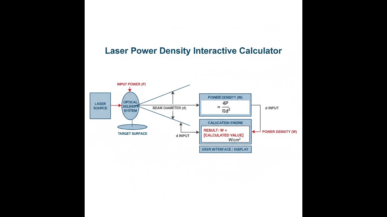
Laser Power Density Diagram

Laser Power Density Calculator
How to Use This Calculator
- Select your Calculation Mode — choose what you want to solve for (power density, beam area, required power, spot diameter, peak density, or energy density).
- Enter the relevant inputs that appear — laser power (W), beam area (mm²), power density (W/mm²), spot diameter (mm), or pulse energy (J) depending on the mode selected.
- Choose your Beam Profile — Uniform (Flat-Top), Gaussian (TEM₀₀), or Annular Ring to match your laser's spatial characteristics.
- Click Calculate to see your result.
Laser Power Density Interactive Visualizer
Watch how beam profile and spot size dramatically affect power concentration. See the instant relationship between laser power, beam area, and material interaction thresholds.
AVG POWER DENSITY
127 W/mm²
PEAK INTENSITY
127 W/mm²
BEAM AREA
0.79 mm²
FIRGELLI Automations — Interactive Engineering Calculators
Laser Power Density Equations
Use the formula below to calculate average laser power density (irradiance).
Average Power Density (Irradiance)
I = P / A
I = Power density (W/mm² or W/cm²)
P = Laser power (W)
A = Beam cross-sectional area (mm² or cm²)
Use the formula below to calculate circular beam area from spot diameter or radius.
Circular Beam Area
A = π r² = π (d/2)²
r = Beam radius (mm)
d = Beam diameter (mm)
Use the formula below to calculate peak intensity for a Gaussian beam profile.
Gaussian Beam Peak Intensity
Ipeak = 2 Iavg = 2P / (π w₀²)
Ipeak = Peak intensity at beam center (W/mm²)
Iavg = Average power density (W/mm²)
w₀ = Beam waist radius at 1/e² points (mm)
Use the formula below to calculate energy density (fluence) for pulsed laser applications.
Energy Density (Fluence) for Pulsed Lasers
F = Epulse / A
F = Energy density or fluence (J/mm² or J/cm²)
Epulse = Energy per pulse (J)
A = Beam area (mm² or cm²)
Use the formula below to calculate the required spot diameter for a target power density.
Spot Diameter from Power Density
d = 2√(P / (π I))
d = Required spot diameter (mm)
P = Laser power (W)
I = Target power density (W/mm²)
Simple Example
A 100 W flat-top laser is focused to a circular spot with a 1.0 mm diameter.
- Beam area: A = π × (0.5)² = 0.785 mm²
- Power density: I = 100 W / 0.785 mm² = 127.4 W/mm²
- Peak intensity (flat-top): 127.4 W/mm² — same as average, since energy is distributed uniformly
- If Gaussian instead: Peak = 2 × 127.4 = 254.8 W/mm² at the beam center
Theory & Engineering Applications of Laser Power Density
Laser power density represents the spatial concentration of optical power and fundamentally determines the laser-matter interaction regime. Unlike total power alone, power density accounts for beam focusing and determines whether a laser system will gently heat a surface, precisely ablate material, or generate plasma. This metric bridges photonics theory with practical material processing, medical procedures, and advanced manufacturing.
Fundamental Physics of Power Density
When electromagnetic radiation interacts with matter, the absorbed power per unit volume drives temperature rise according to the heat equation. However, the surface power density (irradiance) determines the initial energy deposition rate. For continuous-wave lasers, power density measured in W/mm² or W/cm² describes steady-state energy delivery. Most engineering calculations use these units, where 1 W/mm² equals 10,000 W/cm². This distinction matters because older literature frequently uses W/cm², while modern laser systems specify spot sizes in millimeters.
The relationship between beam profile and peak intensity is non-trivial and frequently misunderstood in practice. A uniform (flat-top) beam distributes power evenly across the illuminated area, making average and peak intensities identical. However, most laser resonators produce Gaussian TEM₀₀ modes where intensity follows I(r) = I₀ exp(-2r²/w²), with I₀ representing the peak intensity at the beam center. The commonly cited "1/e² diameter" defines the beam width where intensity drops to 13.5% of peak value. Critically, for Gaussian beams, the peak intensity is exactly twice the average power density—a factor that dramatically affects material damage thresholds and processing outcomes.
Beam Profiles and Spatial Energy Distribution
Real-world laser applications encounter three primary beam profiles, each with distinct power density characteristics. Gaussian beams from single-mode fiber lasers or well-aligned laser resonators offer the highest focusability and predictable intensity distributions. The 2:1 peak-to-average ratio means that material ablation or damage often initiates at the beam center even when average power density suggests safe operation. Fiber lasers typically maintain M² values near 1.0 to 1.2, preserving near-Gaussian profiles through beam delivery systems.
Flat-top or "top-hat" beam profiles, generated through beam shaping optics or multimode fiber delivery, provide uniform illumination across the spot area. These profiles prevent central hot-spots and enable consistent material processing for applications like laser annealing or surface texturing. Beam shapers using diffractive optical elements or Powell lenses can transform Gaussian inputs into near-uniform distributions, though real systems achieve 90-95% uniformity rather than perfect flatness.
Annular ring beams, produced by axicon lenses or specialized optics, concentrate power in a ring pattern. These find applications in laser drilling where a ring-shaped energy distribution prevents central material melting that can trap vapors and reduce drilling efficiency. The peak intensity in annular beams depends heavily on ring geometry—thin rings concentrate power more than wide annuli—making simple 1.5x multipliers approximate at best.
Material Processing Thresholds
Power density determines material processing regime with remarkable precision. Surface heating and conduction-limited processing occurs at 0.1 to 10 W/mm² (1,000 to 100,000 W/cm²), where heat conducts into the workpiece faster than the surface can vaporize. Laser hardening of steel, plastic welding, and paint stripping operate in this regime. The process becomes conduction-limited, controlled by thermal diffusivity rather than incident power.
Keyhole welding and cutting transitions occur between 10 to 100 W/mm², where vaporization begins faster than conduction can dissipate heat. At approximately 40 W/mm² on steel, a vapor cavity or "keyhole" forms, enabling deep penetration welding. This keyhole collapses and reforms at kilohertz frequencies, creating the characteristic spatter and noise of laser welding processes. The exact threshold depends on material properties, wavelength, and temporal pulse characteristics, but power density provides the primary indicator.
Ablation and plasma formation above 100 W/mm² enables laser cutting, drilling, and surface ablation. When power density exceeds 1,000 W/mm² (10 MW/cm²), most materials form plasma plumes that can shield or enhance subsequent energy absorption depending on wavelength. Pulsed lasers with nanosecond or shorter durations achieve these intensities with modest pulse energies by concentrating energy temporally as well as spatially. A 10 mJ pulse delivered in 10 nanoseconds to a 0.1 mm² spot achieves 10,000 W/mm² average power density during the pulse.
Wavelength and Material Absorption
Power density calculations assume energy absorption, but absorptivity varies dramatically with wavelength and material properties. Metals reflect 90-98% of 1064 nm Nd:YAG radiation when cold, but absorptivity increases to 40-60% once surface melting begins. This creates a power density threshold effect—insufficient intensity fails to initiate melting, while slightly higher intensity suddenly couples efficiently. Green (532 nm) and UV (355 nm) wavelengths offer 2-3x higher cold absorptivity in metals, effectively reducing required power density by similar factors.
Transparent materials like glass and many polymers require specific wavelengths for efficient absorption. CO₂ lasers at 10.6 μm couple efficiently to most organics and glasses, while 1064 nm radiation transmits through clear plastics with minimal absorption. This wavelength dependence means identical power densities produce radically different effects depending on laser type. Medical applications exploit this—1064 nm penetrates tissue millimeters for subsurface heating, while 2940 nm Er:YAG radiation absorbs in microns for precise ablation.
Worked Example: Fiber Laser Cutting System Design
A manufacturing engineer is designing a fiber laser cutting system for 3.0 mm thick stainless steel sheets. Research literature indicates reliable through-cutting requires minimum power density of 45 W/mm² at the focus point with a Gaussian beam profile. The facility has purchased a 2.4 kW fiber laser with M² = 1.15 beam quality. What focused spot diameter is required, and what peak intensity will occur at the beam center?
Step 1: Calculate required beam area for target average power density
Using the fundamental relationship I = P / A, rearranging for area:
A = P / I = 2400 W / 45 W/mm² = 53.33 mm²
Step 2: Calculate spot diameter from circular beam area
For a circular beam, A = π(d/2)², solving for diameter:
d = 2√(A/π) = 2√(53.33/3.14159) = 2√(16.974) = 2(4.121) = 8.24 mm
This represents the spot diameter at 1/e² intensity points for the Gaussian beam, where 86.5% of the total power is contained.
Step 3: Calculate peak intensity for Gaussian beam
For a Gaussian TEM₀₀ beam, peak intensity at the beam center is exactly twice the average power density:
Ipeak = 2 × Iavg = 2 × 45 W/mm² = 90 W/mm²
Converting to W/cm² for comparison with literature values: 90 W/mm² × 100 = 9,000 W/cm² = 0.9 MW/cm²
Step 4: Verify focusing optics capability
The required 8.24 mm focused spot diameter must be achievable with available optics. For a fiber laser with beam parameter product (BPP) = λM²/π, at 1070 nm wavelength:
BPP = (1.07 × 10⁻³ mm)(1.15) / π = 0.392 × 10⁻³ mm·rad
Using a focusing lens with focal length f = 200 mm and collimated beam diameter D = 25 mm:
Focused spot diameter = 4λfM² / (πD) = 4(1.07 × 10⁻³)(200)(1.15) / (π × 25) = 0.0125 mm = 12.5 μm theoretical minimum
The 8.24 mm required spot is dramatically larger than the theoretical minimum, indicating intentional defocusing is required. The cutting head must be positioned approximately 5-8 mm above or below the true focal plane to achieve this larger spot size while maintaining sufficient power density. This defocused operation provides more tolerance to surface height variations and reduces edge quality sensitivity to positioning errors.
Step 5: Calculate depth of focus
For Gaussian beams, depth of focus (Rayleigh range × 2) determines the working distance tolerance:
Rayleigh range zR = πw₀²/λ, where w₀ is the beam waist radius
At the defocused position with 8.24 mm diameter: w₀ = 4.12 mm
zR = π(4.12)² / (1.07 × 10⁻³) = 50,070 mm ≈ 50 meters
This extremely long Rayleigh range occurs because the beam is so far from the tight focus point. In practical terms, power density remains within ±10% over several millimeters of z-axis travel, providing excellent tolerance for sheet flatness variations and thermal distortion during cutting.
Pulsed Laser Considerations
Pulsed lasers introduce temporal concentration alongside spatial focusing. Energy density or fluence (J/cm² or J/mm²) becomes the relevant metric for pulsed applications. A Q-switched Nd:YAG laser delivering 400 mJ in a 6 nanosecond pulse to a 0.5 mm diameter spot creates:
Spot area = π(0.25 mm)² = 0.196 mm²
Fluence = 400 mJ / 0.196 mm² = 2,040 J/mm² = 20.4 J/cm²
Peak power during pulse = 400 mJ / 6 ns = 66.7 MW
Instantaneous power density = 66.7 MW / 0.196 mm² = 340 MW/mm² = 3.4 GW/cm²
These gigawatt-level intensities enable nonlinear optical effects, plasma formation, and material ablation with minimal thermal damage to surrounding areas. The heat-affected zone remains confined because thermal diffusion (occurring at microsecond timescales) cannot spread energy during the nanosecond pulse duration.
Safety Classifications and Exposure Limits
Laser safety standards define maximum permissible exposure (MPE) based on wavelength, exposure duration, and beam area. For continuous visible and near-IR lasers (400-1400 nm), the MPE for skin exposure is approximately 0.2 W/cm² (0.002 W/mm²) for extended exposure. Eye safety limits are orders of magnitude lower—roughly 2 mW/cm² (0.00002 W/mm²) for direct viewing at visible wavelengths. Even "low" power densities of 1 W/mm² represent 5,000 times the eye safety limit and 500 times the skin safety limit.
This enormous gap between processing requirements and safety limits explains why laser facilities require stringent engineering controls, beam enclosures, and safety interlocks. A cutting laser operating at 45 W/mm² produces instantaneous permanent retinal damage if viewed directly or via specular reflection. Diffuse reflections from matte surfaces reduce intensity by factors of 10-100 but remain hazardous at close range.
Advanced Applications
Additive manufacturing via laser powder bed fusion requires careful power density control between 100-200 W/mm² to melt metal powder without vaporization or excessive spatter. The process window narrows with higher-reflectivity materials like aluminum and copper, where green lasers (515-532 nm) provide better absorptivity than traditional 1064 nm sources.
Medical laser surgery exploits power density regimes precisely matched to tissue types. Photocoagulation for retinal therapy uses 10-100 mW/mm², while laser lithotripsy for kidney stone fragmentation requires 500-2000 W/mm² in pulsed mode. Femtosecond lasers for LASIK achieve 10,000 W/mm² peak intensities through extreme temporal compression (100 femtosecond pulses), enabling cold ablation through multiphoton absorption rather than thermal effects.
For those seeking additional engineering calculation tools, visit our comprehensive free engineering calculators library featuring resources across optical, mechanical, and electrical engineering disciplines.
Practical Applications
Scenario: Medical Device Manufacturing Quality Control
Dr. Chen, a process engineer at a surgical instrument manufacturer, is troubleshooting inconsistent laser marking quality on titanium hip implants. The marking laser specifications list 20 W average power with a "focused spot diameter" of 0.08 mm, but production parts show both incomplete marks and excessive heat-affected zones. Using the power density calculator in Gaussian beam mode, she calculates the actual power density: with a 0.08 mm diameter spot, the area is 0.00503 mm², yielding an average power density of 3,976 W/mm². More critically, the Gaussian beam profile produces a peak intensity of 7,952 W/mm² at the center—well above the 5,000 W/mm² threshold where titanium begins plasma formation. By deliberately defocusing to 0.12 mm diameter, Dr. Chen reduces peak intensity to 3,537 W/mm², achieving consistent marking without plasma effects. The calculator enabled her to recognize that the vendor's spot diameter specification referred to different measurement criteria than she assumed, and precise power density control resolved the quality issues without equipment replacement.
Scenario: Automotive Laser Welding System Optimization
Marcus, a manufacturing engineer at an electric vehicle battery factory, is designing a laser welding process for copper busbar-to-terminal joints. The facility's new 4.5 kW blue laser (450 nm wavelength) offers superior copper absorption compared to IR lasers, but determining optimal processing parameters requires power density calculations. Literature suggests copper welding requires 65-85 W/mm² average power density for stable keyhole mode. Using the calculator's "Calculate Required Beam Area" mode with 4.5 kW power and target 75 W/mm² density, Marcus finds he needs 60 mm² beam area, corresponding to an 8.74 mm diameter spot. However, his application requires welding a 0.5 mm wide busbar—nearly 18 times smaller than the calculated spot. This reveals he must use only a small fraction of available laser power or implement beam shaping optics. By selecting a 600 W power setting and calculating backward, he determines a 2.83 mm spot delivers 75 W/mm², matching both the physical geometry and process requirements. The calculator prevented a costly mistake of attempting to use full laser power with inappropriate focusing that would have vaporized the thin conductors.
Scenario: Research Lab Laser Safety Assessment
Jennifer, a laser safety officer at a university photonics laboratory, is conducting hazard assessments for a newly installed ultrafast laser system. The Ti:Sapphire laser produces 3.2 mJ pulses at 800 nm wavelength with 150 femtosecond pulse duration, focused to a 30 μm (0.03 mm) diameter spot for nonlinear optics experiments. Using the calculator in "Calculate Energy Density" mode with 0.0032 J pulse energy and a beam area of 0.000707 mm², she calculates an energy density of 4,526 J/mm² (45.26 J/cm²). This enormously exceeds the ANSI Z136.1 maximum permissible exposure of approximately 0.000005 J/cm² for 150 fs pulses at 800 nm—representing nearly 10 million times the safe exposure limit. Even accounting for the calculator's warnings about high power density, Jennifer recognizes that accidental exposure, even from diffuse reflections, could cause instantaneous irreversible retinal damage. She mandates complete beam path enclosure with interlocked access panels, eliminates all specular surfaces within 2 meters of the beam path, and requires wavelength-specific laser safety eyewear rated for optical density 7+ at 800 nm for anyone in the laboratory. The quantitative power density calculation transformed abstract safety guidelines into concrete engineering requirements that protect researchers from invisible but catastrophic hazards.
Frequently Asked Questions
What is the difference between power density and energy density for lasers? +
Why does beam profile (Gaussian vs. flat-top) affect processing results if total power is the same? +
How does laser wavelength affect the power density required for material processing? +
What power density range is typically used for laser cutting versus laser welding? +
How do I convert between W/mm² and W/cm² power density units? +
Why does my laser cutter require defocusing to achieve optimal cutting rather than using the tightest focus? +
Free Engineering Calculators
Explore our complete library of free engineering and physics calculators.
Browse All Calculators →🔗 Explore More Free Engineering Calculators
About the Author
Robbie Dickson — Chief Engineer & Founder, FIRGELLI Automations
Robbie Dickson brings over two decades of engineering expertise to FIRGELLI Automations. With a distinguished career at Rolls-Royce, BMW, and Ford, he has deep expertise in mechanical systems, actuator technology, and precision engineering.
Need to implement these calculations?
Explore the precision-engineered motion control solutions used by top engineers.


